TOPCON DEVICES ERROR LIST - FOR HMI / TC.RCU AND SOFTWARE TOPCONTROL - V11.51 - REGATRON
←
→
Page content transcription
If your browser does not render page correctly, please read the page content below
TopCon devices − Error list
For HMI / TC.RCU and Software TopControl

                                 V11.51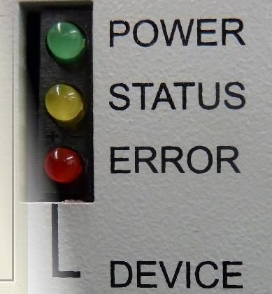
TopCon – Error list                                                                           1

   1. General information
                      © 2021 Regatron AG
                      This document is protected by copyright.
                      All rights, including translation, re-printing and duplication of this manual
                      or parts of it, reserved. No part of this work is allowed to be reproduced,
                      processed, copied or distributed in any form, also not for educational
                      purposes, without the written approval of Regatron.
                      This information in this documentation corresponds to the development
                      situation at the time of going to print and is therefore not of a binding
                      nature. Regatron AG reserves the right to make changes at any time for
                      the purpose of technical progress or product improvement, without
                      stating the reasons. In general we refer to the applicable issue of our
                      “Terms of delivery”.

                                                  2 / 75                                2021-08-17
TopCon – Error list 1
Identification
Manufacturer
Information on the manufacturer
Regatron AG
Feldmuehlestrasse 50
9400 Rorschach
SWITZERLAND
+41 71 846 67 44
www.regatron.com
support@regatron.com
Tab. 1
Instructions
Document identification
Identifier TopCon devices − Error list
Error list Version V11.51
Tab. 2
Open questions
In you have any questions, your TopCon sales partner will be pleased
to be of assistance.
3 / 75 2021-08-17TopCon – Error list 1
Table of contents
1. GENERAL INFORMATION .......................................................................................... 2
Identification .................................................................................................................................................... 3
Manufacturer ................................................................................................................................................. 3
Instructions .................................................................................................................................................... 3
Open questions ............................................................................................................................................. 3
2. ERROR LIST ................................................................................................................ 5
2.1. Introduction ......................................................................................................................................... 5
2.2. Overview of group error codes and group warning codes ............................................................ 7
2.3. Error group .......................................................................................................................................... 9
2.3.1. 0) Internal ..................................................................................................................................... 9
2.3.2. 1) Internal (PDSP) ...................................................................................................................... 11
2.3.3. 2) Output current ........................................................................................................................ 14
2.3.4. 3) Output voltage ....................................................................................................................... 16
2.3.5. 4) Supply .................................................................................................................................... 18
2.3.6. 5) Temperature .......................................................................................................................... 22
2.3.7. 6) Communication ...................................................................................................................... 24
2.3.8. 7) Internal (Modulator) ............................................................................................................... 27
2.3.9. 8) Internal (AD overrange 1) ...................................................................................................... 30
2.3.10. 9) Internal (AD overrange 2) ...................................................................................................... 32
2.3.11. A) Internal (AD underrange 1).................................................................................................... 34
2.3.12. B) Internal (AD underrange 2).................................................................................................... 36
2.3.13. C) Login...................................................................................................................................... 38
2.3.14. D) Configuration ......................................................................................................................... 44
2.3.15. E) Configuration 2 ...................................................................................................................... 47
2.3.16. F) Miscellaneous ........................................................................................................................ 49
2.3.17. G) IBC System ........................................................................................................................... 52
2.3.18. H) IBC Supply ............................................................................................................................ 53
2.3.19. J) IBC Communication ............................................................................................................... 53
2.3.20. K) IBC Power ............................................................................................................................. 54
2.3.21. L) IBC Inverter ............................................................................................................................ 55
2.3.22. M) IBC Miscellaneous ................................................................................................................ 57
2.3.23. N) IBC Inverter 2 ........................................................................................................................ 58
2.3.24. Q) Configuration 4 ...................................................................................................................... 59
2.3.25. R) Miscellaneous 2 .................................................................................................................... 62
2.3.26. S) Supply 2................................................................................................................................. 64
2.3.27. T) Login 2 ................................................................................................................................... 65
2.3.28. U) Configuration 3 ...................................................................................................................... 67
2.3.29. V) Communication 3 .................................................................................................................. 71
2.3.30. W) Internal 2............................................................................................................................... 74
2.3.31. X) Communication 2 .................................................................................................................. 75
4 / 75 2021-08-17TopCon – Error list Error list 2
2. Error list
2.1. Introduction
Division into group and detail errors
To be able to troubleshoot errors as quickly and accurately as possible,
the possible errors are divided into 16 group errors. Each of these
group errors is in turn broken down into 16 detail errors.
The group and detail errors can be identified by direct digital access (via
TopControl or HMI/RCU). Group errors and detail errors are also
indicated sequentially on the front panel via a flashing code on the red
“ERROR” light emitting diode.
There is the same mechanism for warnings. They are indicated on the
front panel via the yellow “STATUS” light emitting diode or can be
polled via TopControl and HMI/RCU.
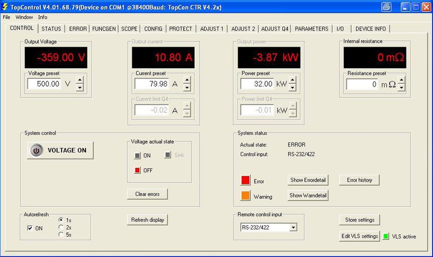
Acknowledging an error
On the occurrence of an error, the device remains in the ERROR state
until the error is acknowledged and the device signals this state
correspondingly with the digital outputs (relay) and the light emitting
diodes on the front panel.
The positive edge on the Clear Error signal is used to acknowledge an
error. The digital input provided for this purpose or the related control
parameter (direct digital access) is used.
Control signals in case of an error
Power up
Clear Error
Voltage_ON
Clearing
Output
Error
voltage
State 2 4 8 12 4
Fig. 1 Control signals in case of an error.
Errors and acknowledging
The warnings are also saved until they are acknowledged. The positive
edge of the Clear Error signal is used for this purpose.
Errors can also be acknowledged via the TopControl application and via
the HMI/RCU.
5 / 75 2021-08-17TopCon – Error list Error list 2
Error and warning indication on the front panel LEDs
The number of flashes indicates the possible reasons for the
malfunction (group error and detail error). The following illustration
shows a period in the indication cycle.
1s 0.2s
2s 1.5s 1s
0.2s
Start 1 2 3 nG Break 1 2 3 4 5 nD Break Start
Group error code Detail error code
Errors are indicted via the red ERROR LED; warnings via the yellow
STATUS LED.
Error codes and warning codes are identical. All errors and warnings
are output one after the other based on the scheme above. Then the
flashing sequence starts again with the first error or first warning.
The chapter lists all flashing codes and provides information on the
reason for the error and how to rectify it.
6 / 75 2021-08-17TopCon – Error list Error list 2
2.2. Overview of group error codes
and group warning codes
Indication of the reason for the malfunction
Flash 1) Error groups Page
code
1 0) Internal 9
2 1) Internal (PDSP) 11
3 2) Output current 11
4 3) Output voltage 16
5 4) Supply 18
6 5) Temperature 22
7 6) Communication 24
8 7) Internal (Modulator)) 27
9 8) Internal (AD overrange 1) 30
10 9) Internal (AD overrange 2) 32
11 A) Internal (AD underrange 1) 34
12 B) Internal (AD underrange 2) 34
13 C) Login 38
14 D) Configuration 44
15 E) Configuration 2 47
16 F) Miscellaneous 49
17 G) IBC System 52
18 H) IBC Supply 53
19 J) IBC Communication 53
20 K) IBC Power 54
21 L) IBC Inverter 55
22 M) IBC Miscellaneous 57
23 N) IBC Inverter 2 58
24 P) not used ---
25 Q) Configuration 4 59
26 R) Miscellaneous 2 62
27 S) Supply 2 64
28 T) Login 2 65
29 U) Configuration 3 67
30 V) Communication 3 71
31 W) Internal 2 67
32 X) Communication 2 75
1) On the HMI/RCU there is not enough space to output the errors or warnings with as
much detail as in TopControl. I.e. the text may be indicated truncated. The code in
front of the text is however identical in TopControl and HMI/RCU
The above list provides an overview of all existing group errors. Some
of the groups can also occur as warnings via the same group code.
The code prefix [ 0) ... X) ] helps to clearly identify the error
group/warning group. This code appears both in TopControl ("Show
Errordetail" / "Show Warndetail" buttons) and also on the HMI/RCU
(Error/Warning menu).
7 / 75 2021-08-17TopCon – Error list Error list 2
Overview of detail errors and detail warning codes
The following table lists all detail errors. Some of the detail errors can
also occur as warnings with the same code.
The error or the warning can be identified using the flashing code in
column 1 based on the number of flashes on the front panel LEDs.
The “TopControl/HMI indication” column contains the exact wording in
TopControl (“Show Errordetail” / ”Show Warndetail” button). The texts
are truncated on the HMI/RCU for space reasons. The errors can
however be unambiguously identified from the code given first.
8 / 75 2021-08-17TopCon – Error list Error group − 0) Internal 2
2.3. Error group
2.3.1. 0) Internal
Flash Error message
Error Description Possible Cause Counteraction
Code TopCon (Long)
An invalid internal state was In the case of repeated
1-1 00 Invalid system state detected. occurrence refer to customer no
(Used for debugging pur-pose). support .
An invalid internal state was In the case of repeated
Invalid module
1-2 01 detected. occurrence refer to customer no
state
(Used for debugging pur-pose). support .
Calculation The internal calculation overflow is Wrong parameters are set. Possily Make sure that the correct Update-Gridfile has
1-3 02
Overflow prevented. after a firmware update been used when applying the firmware update
Tried to e.g. store more function Delete some unused function sequences an try
1-4 03 Flash full Internal non-volatile memory is full
sequneces than possible. again
Write error in the non-volatile You have made an update from
EEPROM table After power up activate button "Store settings"
1-5 04 memory when storing device Version V4.11.33 or older to
write and restart device.
parameters. V4.11.34 or new-er.
In the case of repeated
Timeout while writing or deleting a
1-6 05 Flash timeout occurrence refer to customer no
flash page.
support
Extensive measures to thoroughly earth the device
A strong EMI pulse affects the AD is needed.
1-7 06 ADC sequence AD converter sequence is incorrect.
data stream or hardware defect. Find the EMI sources e.g. contactors without free
wheeling diodes
In the case of repeated
Invalid EEPROM Empty or invalid table of device
1-8 07 occurrence refer to customer no
table parameters.
support.
An unexpected change of state was In the case of repeated
Requested state
1-9 08 detected. (Used for debugging occurrence refer to customer no
not available
purpose). support.
9 / 75 2021-08-17TopCon – Error list Error group − 0) Internal 2
Flash Error message
Error Description Possible Cause Counteraction
Code TopCon (Long)
Tried to switch on output (voltage-
on) when DCLink voltage and/or
Thyristor not The Thyristor switch for DC link load mains voltage error limit is Make sure mains voltage of each phase is within
1-10 09
switched on resistor isn’t switched on. reached but that error was not yet valid range.
reported because of a
programmed delay.
No active system controller was In the case of repeated
No active controller
1-11 0A defined or identified. (Used for occurrence refer to customer no
defined
debugging pur-pose). support.
An internal timeout oc-curred during
1-12 0B ADC timeout Implied by error 06) See above error 06)
data acquisition.
ADC DMA interrupt Incomplete collection of the current
1-13 0C Implied by error 06) See above error 06)
missing status.
In the case of repeated
1-14 0D Internal debug error occurrence refer to customer
support .
An unexpected interrupt routine was In the case of repeated
Invalid interrupt
1-15 0E called. occurrence refer to customer no
routine called
(Used for debugging pur-pose). support .
Make sure that the correct Update-Gridfile has
The version stored in the device
Old EEPROM table Can appear after a firmware been used when applying the firmware update.
1-16 0F parameter table differs from the
loaded update of the main DSP. (See also in the manual in section software
updated software version.
update).
10 / 75 2021-08-17TopCon – Error list Error group − 1) Internal (PDSP) 2
2.3.2. 1) Internal (PDSP)
Flash Error message
Error Description Possible Cause Counteraction
Code TopCon (Long)
Extensive measures to thor-oughly earth the
PDSP pack-age device is needed.
2-1 10 System communication failed. A strong EMI pulse.
check-sum Find the EMI sources e.g. contactors without free
wheeling diodes.
The peripheral DSP wasn’t
The version of the peripheral DSP successfully refreshed during a
Wrong PDSP SW You have to follow the Soft-ware update
2-2 11 does not support the version of the software update.
version instructions in the manual.
main DSP. Newest parameters aren’t loaded
after a software update.
In the case of repeated
2-3 12 PDSP fault An internal error occurred. occurrence refer to customer no
support.
In the case of repeated
Write queue
2-4 13 An internal error occurred. occurrence refer to customer no
overrun
support.
In the case of repeated
Too many PDSP
2-5 14 An internal error occurred. occurrence refer to customer no
packages
support.
Extensive measures to thor-oughly earth the
device is needed.
Use a shorter cable.
Use a shielded cable.
2-6 15 SCI check-sum Various errors on interface RS232. Interference on the RS232 cable.
Prevent ground loops. Use a voltaic isolated
RS232 interface.
Find the EMI sources
e.g. contactors without free wheeling diodes.
Wrong RS232 timings are set Correct the settings according to the device
2-7 16 SCI parity Various errors on interface RS232.
(baud rate, stop bit, parity bit, ...). manual.
Wrong RS232 timings are set Correct the settings according to the device
2-8 17 SCI overrun Various errors on interface RS232.
(baud rate, stop bit, parity bit, ...). manual.
11 / 75 2021-08-17TopCon – Error list Error group − 1) Internal (PDSP) 2
Flash Error message
Error Description Possible Cause Counteraction
Code TopCon (Long)
Plug in the RS232 cable after booting PC/laptop
Level switching on RS232
and re-move it before shut-down.
2-9 18 SCI framing Various errors on interface RS232. Interface while PC/Laptop is
Update the peripherals DSP to at least version
switched on/off .
0.11.
On host side, a wrong level for an Update the peripherals DSP to at least version
inactive state exists, while the 0.11.
2-9 18 SCI framing Various errors on interface RS232.
RS232- interface hasn’t been Start TopControl: when running, the interface is
opened opened. Acknowledge the error (“Clear error”).
2-10 19 SCI break Various errors on interface RS232.
In the case of repeated
Unknown SCI Undefined internal communication.
2-11 1A occurrence refer to customer no
status bit (Used for debugging purpose).
support .
In the case of repeated
Unknown CAN Undefined internal communication.
2-12 1B occurrence refer to customer no
status bit (Used for debugging purpose).
support .
In the case of repeated
Unknown PDSP Undefined internal communication.
2-13 1C occurrence refer to customer no
package (Used for debugging purpose).
support .
Occurs at start with firm-ware
v4.11.30 while con-trolling at least
Received a CAN pack-age from a
Package from not 4 inter-connected devices. Is to be
2-14 1D not initialized CAN mailbox.(Used for no
initialised mailbox ignored in this case.
debugging purpose).
In other constellations, refer to the
customer support
PDSP Communication to the peripheral In the case of repeated
2-15 1E communication DSP occurrence refer to customer no
stopped failed. support.
SCI timeout within Timeout while receiving a TALK RS232 communication was
2-16 1F See above errors 15-19
a talk frame. frame by RS232 disconnected or interrupted.
SCI timeout within Timeout while receiving a TALK
2-16 1F Consequence of error 18. See above errors 15-19
a talk frame. frame by RS232
12 / 75 2021-08-17TopCon – Error list Error group − 1) Internal (PDSP) 2
Flash Error message
Error Description Possible Cause Counteraction
Code TopCon (Long)
All bytes of a TALK Frame have to be sent
On host side (PC) the
SCI timeout within Timeout while receiving a TALK between 5 ms (peripherals DSP version V0.09 /
2-16 1F implementation of the TALK-
a talk frame. frame by RS232 V0.10) and 200ms (from PDSP version v0.11
protocol is too slow.
upwards and devices with CTR4.20).
13 / 75 2021-08-17TopCon – Error list Error group − 2) Output current 2
2.3.3. 2) Output current
Flash Error message
Error Description Possible Cause Counteraction
Code TopCon (Long)
Calculated loss energy [(Ilimit)2– Current during some time exceeds
3-1 20 i2t Adjust the current llimit or l^2t to load
(Iout)2] * t exceeds the limit I2tmax.. current limit.
Output current exceeds the set level Controller overshooting caused by Decrease steps of set value ramp.
3-2 21 Overcurrent Isek
during a particular delay time. set value steps. Adapt controller parameters to the load.
Output current exceeds the set level
3-2 21 Overcurrent Isek Controller overshooting Decrease controller parameters
during a particular delay time.
Strong additional switching on of a A temporary voltage drop is reduced by adding an
Output current exceeds the set level low resistive load produces a exter-nal capacitor or a serial in-ductance.
3-2 21 Overcurrent Isek
during a particular delay time. current peak (result of the output After a consultation with customer support, where
capacitance). appropriate, increase the delay.
The transformer current exceeds the
Controller overshooting by set Reduce the gradient of the set value ramp.
3-3 22 Overcurrent Iprim preset level (Level is dependent on
value jumps. Decreasing controller parameters.
the temperature).
The transformer current exceeds the Strong additional switching on of a A temporary voltage drop is reduced by applying
3-3 22 Overcurrent Iprim preset level (Level is dependent on low resistive load (fast and large a exter-nal capacitance or serial inductance.
the temperature). voltage drop). Decrease of controller parameters.
The transformer current exceeds the
3-3 22 Overcurrent Iprim preset level (Level is dependent on Hardware defect. Contact customer support
the temperature).
Hardware current monitoring.
Detection of short circuits with
3-4 23 Gatedrive A fault Cf. “22) Overcurrent Iprim“ Cf. “22) Overcurrent Iprim“
immediate switching off the power
stage.
Hardware current monitoring.
Detection of short circuits with
3-5 24 Gatedrive B fault Cf. “23) Overcurrent Iprim“ Cf. “23) Overcurrent Iprim“
immediate switching off the power
stage.
14 / 75 2021-08-17TopCon – Error list Error group − 2) Output current 2
Flash Error message
Error Description Possible Cause Counteraction
Code TopCon (Long)
Cut-off level of current was reduced
Overcurrent Isek
because of high temperature (from Lower ambient temperature and/or
3-6 25 (level de-rated by Cf. „21) Overcurrent Isek“
110% to 100% device maximum cf. „21) Overcurrent Isek“
tem-perature)
current) Cf. 21)
The TC.LIN output current exceeded
3-7 26 TC.LIN Overcurrent the upper current level for a specific Cf. „21) Overcurrent Isek“ no
time.
Safe Operating Area (SOA) Reduce the output current and/or drop voltage
3-8 27 TC.LIN Overload Cf. „21) Overcurrent Isek“
exceeded over TC.LIN.
Arc detection
3-9 28
threshold reached
Output current in sink operation (Q4)
Overcurrent Isek
3-10 29 exceeds the set level during a Cf. „21) Overcurrent Isek“
Q4
paricular time. Cf. 21)
Overcurrent Isek
3-11 2A Q4 (level derated Cf. 25) Cf. „21) Overcurrent Isek“
by temperature)
Overcurrent output Inductor current on DC output
3-12 2B Cf. „21) Overcurrent Isek“
inductor exceeds specified limit
A battery is connected to the
Check if no battery is connected to the ouput.
Overrcurrent DC Current on DC Discharge Unit output.
3-13 2C Check if the connected load does not violate the
Discharge Unit exceeds specified limit The connected load violate the
specified limits.
specified limits.
Overcurrent on
Current on customised power board TC.ACP: Wrong parameters for TC.ACP: Check the parameters for the control of
3-14 2D customised power
exceeds specified limit the control of the H bridge the H bridge
board
15 / 75 2021-08-17TopCon – Error list Error group − 3) Output voltage 2
2.3.4. 3) Output voltage
Flash Error message
Error Description Possible Cause Counteraction
Code TopCon (Long)
Activate load rejection detection.
Increase the controller parameters.
The voltage exceeded the set level Load rejection while voltage was Use adaptive controller parameters.
4-1 30 Overvoltage
for a predefined duration. already on a high level. Add an additional external capacitor.
After consultation with Top-Con support, where
appropriate, increase the error delay.
The voltage exceeded the set level Decrease controller parameters - possibly
4-1 30 Overvoltage Controller overshooting
for a predefined duration. increasing the proportional part (P Gain).
Reduce the gradient of the set value ramp.
The voltage exceeded the set level Overshooting caused by set value Reduce controller parameters.
4-1 30 Overvoltage
for a predefined duration. steps. Overshooting in open loop: use adaptive
Controller pa-rameters.
Adapt the detection level and delay to actual
The difference of module voltage The difference of module voltage
conditions. Possibly deactivate the detection if it is
Max. sense voltage minus sense voltage has exceeded minus sense voltage has
4-2 31 not necessary
drop reached the set limit for a specific duration exceeded the set limit for a
Use low resistance load feed cable.
(delay). specific duration (delay).
Don’t disconnect the load feed cable.
The TC.LIN output voltage exceeded The TC.LIN output voltage
TC.LIN
4-3 32 the over voltage limit for a specific exceeded the over voltage limit for Cf. 30)
Overvoltage
duration. a specific duration.
TopCon has sensed a negative
Check the polarity of sense wires and polarity of
4-4 33 Sense polarity sense voltage! Connection with reversed polarity
the power cords.
Reverse Polarity error.
TopCon had multiple faults keeping
Voltage holding level too low. Adjust controller parameters, increase the limits
RPP-Voltage the output voltage in preconfigured
4-5 34 Extreme controller pa-rameter that Perhaps parameter adjustment after contact with
unstable limits. This is necessary to be able to
led to oscillation. manufacturer.
switch the RPP switch
RSC: Sense voltage is over the Battery to DC ouput connect or
RSC: Usense to Disconnect battery or wait for discharging
4-6 35 default value to switching the Relais capacitor from Inverter not fully
high for switching capacitors.
for configuration the switch box. discharged
16 / 75 2021-08-17TopCon – Error list Error group − 3) Output voltage 2
Flash Error message
Error Description Possible Cause Counteraction
Code TopCon (Long)
Output The voltage fall below the set level Decrease controller parameters - possibly
4-7 36 Controller undershooting
undervoltage for a predefined duration. increasing the proportional part (P Gain).
Output The voltage fall below the set level Undershooting caused by set Reduce the gradient of the set value ramp.
4-7 36
undervoltage for a predefined duration. value steps. Reduce controller parameters.
Output The voltage fall below the set level The given reference value is too
4-7 36 Increase reference value.
undervoltage for a predefined duration. low.
Overvoltage DC Voltage on DC Discharge Unit The connected load violate the Check if the connected load does not violate the
4-8 37
Discharge Unit exceeds specified limit specified limits. specified limits.
Overvoltage on
Voltage on customised power board TC.ACP: Wrong parameters for TC.ACP: Check the parameters for the control of
4-9 38 customised power
exceeds specified limit the control of the H bridge the H bridge
board
Sense line for measuring the
RSC: Sense Sense line for measuring the switch
4-10 39 switch voltage is not connected or Check the Sense line.
missing voltage is not connected.
is interrupted.
17 / 75 2021-08-17TopCon – Error list Error group − 4) Supply 2
2.3.5. 4) Supply
Flash Error message
Error Description Possible Cause Counteraction
Code TopCon (Long)
TC.LIN +5 V too Internal supply voltage is outside of Badly adjusted internal Correction after a consultation with customer
5-1 40
high the valid range. parameters. support.
TC.LIN +5 V too Internal supply voltage is outside of
5-1 40 Hardware defect. Contact customer support
high the valid range.
TC.LIN +5 V too Internal supply voltage is outside of Subsequent error of error “07)
5-1 40 See below ,error 07)
high the valid range. (wrong gain values)”.
TC.LIN +5 V too Internal supply voltage is outside of Badly adjusted internal Correction after a consultation with customer
5-2 41
low the valid range. parameters. support.
TC.LIN +5 V too Internal supply voltage is outside of
5-2 41 Hardware defect. Contact customer support
low the valid range.
TC.LIN +5 V too Internal supply voltage is outside of Subsequent error of error “07)
5-2 41 See below ,error 07)
low the valid range. (wrong gain values)”.
Internal supply voltage is outside of Badly adjusted internal Correction after a consultation with customer
5-4 43 +5V too low
the valid range. parameters. support.
Internal supply voltage is outside of
5-4 43 +5V too low Hardware defect. Contact customer support
the valid range.
Internal supply voltage is outside of Subsequent error of “24V too low/
5-4 43 +5V too low See below, errors 4B/4C)
the valid range. too high”.
Internal supply voltage is outside of Subsequent error of error “07)
5-4 43 +5V too low See below ,error 07)
the valid range. (wrong gain values)”.
Internal supply voltage is outside of Badly adjusted internal Correction after a consultation with customer
5-5 44 +5V too high
the valid range. parameters. support.
Internal supply voltage is outside of
5-5 44 +5V too high Hardware defect. Contact customer support
the valid range.
Internal supply voltage is outside of Subsequent error of “24V too low/
5-5 44 +5V too high See below, errors 4B/4C)
the valid range. too high”.
18 / 75 2021-08-17TopCon – Error list Error group − 4) Supply 2
Flash Error message
Error Description Possible Cause Counteraction
Code TopCon (Long)
Internal supply voltage is outside of Subsequent error of error “07)
5-5 44 +5V too high See below ,error 07)
the valid range. (wrong gain values)”.
Internal supply voltage is outside of Badly adjusted internal Correction after a consultation with customer
5-6 45 +15V too low
the valid range. parameters. support.
Internal supply voltage is outside of
5-6 45 +15V too low Hardware defect. Contact customer support
the valid range.
Internal supply voltage is outside of Subsequent error of “24V too low/
5-6 45 +15V too low See below, errors 4B/4C)
the valid range. too high”.
Internal supply voltage is outside of Subsequent error of error “07)
5-6 45 +15V too low See below ,error 07)
the valid range. (wrong gain values)”.
Internal supply voltage is outside of Badly adjusted internal Correction after a consultation with customer
5-7 46 +15V too high
the valid range. parameters. support.
Internal supply voltage is outside of
5-7 46 +15V too high Hardware defect. Contact customer support
the valid range.
Internal supply voltage is outside of Subsequent error of “24V too low/
5-7 46 +15V too high See below, errors 4B/4C)
the valid range. too high”.
Internal supply voltage is outside of Subsequent error of error “07)
5-7 46 +15V too high See below ,error 07)
the valid range. (wrong gain values)”.
Internal supply voltage is outside of Badly adjusted internal Correction after a consultation with customer
5-8 47 -15V too low
the valid range. parameters. support.
Internal supply voltage is outside of
5-8 47 -15V too low Hardware defect. Contact customer support
the valid range.
Internal supply voltage is outside of Subsequent error of “24V too low/
5-8 47 -15V too low See below, errors 4B/4C)
the valid range. too high”.
Internal supply voltage is outside of Subsequent error of error “07)
5-8 47 -15V too low See below ,error 07)
the valid range. (wrong gain values)”.
Internal supply voltage is outside of Subsequent error of “24V too low/
5-8 47 -15V too low Contact customer support
the valid range. too high”.
19 / 75 2021-08-17TopCon – Error list Error group − 4) Supply 2
Flash Error message
Error Description Possible Cause Counteraction
Code TopCon (Long)
Internal supply voltage is outside of Subsequent error of error “07)
5-8 47 -15V too low Contact customer support
the valid range. (wrong gain values)”.
Internal supply voltage is outside of
5-8 47 -15V too low Hardware defect. Contact customer support
the valid range.
Internal supply voltage is outside of Badly adjusted internal Correction after a consultation with customer
5-9 48 -15V too high
the valid range. parameters. support.
Internal supply voltage is outside of Badly adjusted internal Correction after a consultation with customer
5-9 48 -15V too high
the valid range. parameters. support.
Internal supply voltage is outside of Subsequent error of “24V too low/
5-9 48 -15V too high Contact customer support
the valid range. too high”.
Internal supply voltage is outside of Subsequent error of “24V too low/
5-9 48 -15V too high See below, errors 4B/4C)
the valid range. too high”.
Internal supply voltage is outside of Subsequent error of error “07)
5-9 48 -15V too high See below ,error 07)
the valid range. (wrong gain values)”.
Internal supply voltage is outside of
5-9 48 -15V too high Hardware defect. Contact customer support
the valid range.
5-10 49 DC link voltage low DC link voltage too low Mains voltage too low. Check mains voltage
DC link voltage too low. (Preset
5-10 49 DC link voltage low Feed cable cross-section to small. Choose a cable with sufficient cross-section
output values cannot be reached).
DC link voltage too low. (Preset Bad contact of one or more of the Check for not using a bad connection and check
5-10 49 DC link voltage low
output values cannot be reached). mains phases connections con-nection of cable
DC link voltage too low. (Preset
5-10 49 DC link voltage low Hardware defect Contact customer support
output values cannot be reached).
DC link voltage too
5-11 4A DC link voltage too high Mains voltage too high Check mains voltage
high.
5-12 4B +24V too low 24V mains voltage too low 24V mains voltage too low Check mains voltage.
External load of the internal 24V Reduce the load (raise resistance) so that the
5-13 4B +24V too low 24V mains voltage too low voltage supply too large (e.g. via maximum current specified for the 24V supply is
X105 interface). not exceeded.
5-13 4B +24V too low 24V mains voltage too low Hardware defect Contact manufacturer.
5-13 4C +24V too high 24V mains voltage too high Mains voltage too high. Check mains voltage.
5-13 4C +24V too high 24V mains voltage too high. Hardware defect Contact customer support.
20 / 75 2021-08-17TopCon – Error list Error group − 4) Supply 2
Flash Error message
Error Description Possible Cause Counteraction
Code TopCon (Long)
Voltage drop at inter-mediate circuit
Fast voltage drop voltage within short time (especially
5-14 4D Feed cable cross-section to small Choose a cable with ade-quate cross-section
on DC link when additional switching on
load/start).
Voltage drop at inter-mediate circuit
Fast voltage drop voltage within short time (especially
5-14 4D Failure of one main phase. Check mains phases voltage
on DC link when additional switching on
load/start).
Voltage drop at inter-mediate circuit
Fast voltage drop voltage within short time (especially
5-14 4D DC link thyristor doesn’t switch on. Contact customer support
on DC link when additional switching on
load/start).
Voltage drop at inter-mediate circuit
Fast voltage drop voltage within short time (especially
5-14 4D Hardware defect Contact customer support
on DC link when additional switching on
load/start).
TC.LIN +15V too Internal supply voltage is outside of Correction after a consultation with customer
5-15 4E Wrong alignment of voltage.
high the valid range. support.
TC.LIN +15V too Internal supply voltage is outside of
5-16 4F Hardware defect Contact customer support.
low the valid range.
21 / 75 2021-08-17TopCon – Error list Error group − 5) Temperature 2
2.3.6. 5) Temperature
Flash Error message
Error Description Possible Cause Counteraction
Code TopCon (Long)
Insufficient supply and exhaust air Replace clogged filter. Allow supply and exhaust
flow of cooling air. air sufficiently flow without limitation.
Rectifier temp. too Heat sink temperature near output
6-1 50 Ambient temperature too high. Reduce ambient temperature to allowed range.
high rectifier too high.
Load current too high Adapt load to ambient temperature (Notice the
(temperature rises). temperature derating).
Insufficient supply and exhaust air Replace clogged filter. Allow supply and exhaust
flow of cooling air. air sufficiently flow without limitation.
IGBT temp. too Heat sink temperature near IGBT
6-2 51 Ambient temperature too high. Reduce ambient temperature to allowed range.
high power stage too high.
Load current too high Adapt load to ambient temperature (Notice the
(temperature rises). temperature derating).
Supply and exhaust air flow of
TC.LIN K1 temp. Heat sink temperature of TC.LIN
6-3 52 cooling air is restricted or the Cf. 50) and 51)
too high output stage too high.
ambient temperature is too high.
Supply and exhaust air flow of
TC.LIN K2 temp. Heat sink temperature of TC.LIN
6-4 53 cooling air is restricted or the Cf. 50) and 51)
too high output stage too high.
ambient temperature is too high.
Supply and exhaust air flow of
TC.LIN PCB temp. Temperature of TC.LIN PCB too
6-5 54 cooling air is restricted or the Cf. 50) and 51)
too high high.
ambient temperature is too high.
Temperature inside of TopCon
Case Inside housing exceeds the Temperature of environment (e.g. Increase air circulation, provide cold air intake.
6-6 55
temp.high limitsTemperature of environment of cabinet) too high Cf. 50) and 51)
(e.g. of cabinet) too high
TC.LIN K1 cable TC.LIN Temperature Sensor K1 Cable break or sensor not
6-7 56 Contact customer support
break gives no signal connected
TC.LIN K2 cable TC.LIN Temperature Sensor K2 Cable break or sensor not
6-8 57 Contact customer support
break gives no signal connected
TC.LIN PCB cable TC.LIN Temperature Sensor on PCB
6-9 58 Sensor not mounted Contact customer support
break gives no signal
22 / 75 2021-08-17TopCon – Error list Error group − 5) Temperature 2
Flash Error message
Error Description Possible Cause Counteraction
Code TopCon (Long)
Transformer temp. Transformer temperature exceeds Load current too high (Notice the
6-10 59 Adapt load to ambient temperature (derating).
high the limit. temperature derating).
Insufficient supply and exhaust air Replace clogged filter. Allow supply and exhaust
flow of cooling air. air sufficiently flow without limitation.
PFC temperature Heat sink temperature near PFC too
6-11 5A Ambient temperature too high. Reduce ambient temperature to allowed range.
high high.
Load current too high Adapt load to ambient temperature (Notice the
(temperature rises). temperature derating).
DC Discharge Unit Supply and exhaust air flow of Replace clogged filter. Allow supply and exhaust
DC Discharge Unit temperature
6-12 5B temperature too cooling air is restricted or the air sufficiently flow without limitation.
exceeds the limit.
high ambient temperature is too high. Reduce ambient temperature to allowed range.
Insufficient supply and exhaust air Replace clogged filter. Allow supply and exhaust
PCB temperature Temperature on main controller
6-13 5C flow of cooling air. air sufficiently flow without limitation.
high board exceeds the limit
Ambient temperature too high. Reduce ambient temperature to allowed range.
23 / 75 2021-08-17TopCon – Error list Error group − 6) Communication 2
2.3.7. 6) Communication
Flash Error message
Error Description Possible Cause Counteraction
Code TopCon (Long)
A termination resistor is necessary on both ends of
CAN-Bus termination resistor not the CAN bus (X101/102 connector) when
7-1 60 CAN bus off CAN-Controller error.
connected interconnecting two or more devices (otherwise
only one termination needed)
CAN cable isn’t connected Assure that all cables are properly connected to
7-1 60 CAN bus off CAN-Controller error.
correctly. the devices.
Not allowed Y-cabling of CAN- Do not exceed the maximum length of 30 cm of
7-1 60 CAN bus off CAN-Controller error.
Bus. branch line.
Large noise level affects the Find noise sources and try turning them off to
7-1 60 CAN bus off CAN-Controller error.
CAN-Bus identify the cause.
7-1 60 CAN bus off CAN-Controller error. CAN-cable defect Replace cable.
All CAN bus subscribers, which are not a TopCon-
Non-TopCon CAN bus
7-1 60 CAN bus off CAN-Controller error. devices, TC.LIN or HMI/RCU have to be removed
subscribers interfere with the bus.
to identify the cause.
A termination resistor is necessary on both ends of
CAN-Bus termination resistor not the CAN bus (X101/102 connector) when
7-2 61 CAN error passive CAN-Controller error.
connected interconnecting two or more devices (otherwise
only one termination needed)
CAN cable isn’t connected Assure that all cables are properly connected to
7-2 61 CAN error passive CAN-Controller error.
correctly. the devices.
Not allowed Y-cabling of CAN- Do not exceed the maximum length of 30 cm of
7-2 61 CAN error passive CAN-Controller error.
Bus. branch line.
Large noise level affects the Find noise sources and try turning them off to
7-2 61 CAN error passive CAN-Controller error.
CAN-Bus identify the cause.
7-2 61 CAN error passive CAN-Controller error. CAN-cable defect Replace cable.
All CAN bus subscribers, which are not a TopCon-
Non-TopCon CAN bus
7-2 61 CAN error passive CAN-Controller error. devices, TC.LIN or HMI/RCU have to be removed
subscribers interfere with the bus.
to identify the cause.
CAN write to Internal conflict between DSP and In case of repeated occurrence In case of repeated occurrence refer to customer
7-3 62
mailbox denied CAN-Controller. refer to customer support support
24 / 75 2021-08-17TopCon – Error list Error group − 6) Communication 2
Flash Error message
Error Description Possible Cause Counteraction
Code TopCon (Long)
CAN transmission Internal conflict between DSP and In case of repeated occurrence In case of repeated occurrence refer to customer
7-4 63
aborted CAN-Controller. refer to customer support support
CAN receive Internal conflict between DSP and In case of repeated occurrence In case of repeated occurrence refer to customer
7-5 64
message lost CAN-Controller. refer to customer support support
The device with master role gets no
HMI/RCU does not Supply voltage for a
7-6 65 response from interface unit HMI or Check RCU supply voltage.
respond corresponding HMI / RCU too low.
RCU.
The device with master role gets no
HMI/RCU does not
7-6 65 response from interface unit HMI or Communication interruptions. Cf. 60) and 61)
respond
RCU.
Subsequent error from error
60/61):
CAN transmit Internal conflict between DSP and In the case of repeated occurrence refer to
7-7 66 No CAN bus participant receives
queue overrun CAN-Controller. customer support (if no subsequent error).
data. Or (if no subsequent error):
Internal Problem
Slave does not The master does not receive data
7-8 67 Communication interruptions. Cf. 60) and 61)
respond from all connected devices.
Slave does not The master does not receive data
7-8 67 Slave was switched off Check the mains supply of slaves.
respond from all connected devices.
Optional external measuring box
7-9 68 RMB not connected Supply voltage of RMB too low. Check supply voltage.
(RMB) is not connected
Optional external measuring box Optical fibre is not correctly Check the correct mounting of the optical fibre
7-9 68 RMB not connected
(RMB) is not connected connected. cable.
Slave does not get A slave does not get data from
7-10 69 The master is switched off. Check the mains supply of master
data from master master
Slave does not get A slave does not get data from
7-10 69 Communication error. Cf. 60) and 61)
data from master master
Slave does not get A slave does not get data from Error caused by a failed login or a Cf. group errors C) and D) (if applicable note error
7-10 69
data from master master wrong system configuration. messages of master device).
25 / 75 2021-08-17TopCon – Error list Error group − 6) Communication 2
Flash Error message
Error Description Possible Cause Counteraction
Code TopCon (Long)
between TC.LIN and TopCon (after a
Reattach cable,
TC.LIN does not previously successful
7-11 6A Communication error. acknowledging the error via master,
respond communication). TC.LIN ceased
device restart system.
sending data.
Reattach cable,
General error on system CAN acknowledging the error via master,
7-12 6B TC.LIN CAN error Communication error.
connection. device restart system.
Further counteraction CF. 60) / 61)
RS232 communication failed
No watchdog reset command was
RS232 Watchdog Timeout in optional internal sent to the device, within the Serve watchdog more often
7-13 6C
error watchdog for RS232 interface configured timeout time (needs to Check Communication line
be re-sent periodically while
watchdog enabled).
IBC receive
Internal error on communication with
7-14 6D communication Contact customer support
IBC board
error
IBC transmit
Internal error on communication with
7-15 6E communication Contact customer support
IBC board
error
Internal error on communication with
7-16 6F IBC Talk timeout Contact customer support
IBC board
26 / 75 2021-08-17TopCon – Error list Error group − 7) Internal (Modulator) 2
2.3.8. 7) Internal (Modulator)
Flash Error message
Error Description Possible Cause Counteraction
Code TopCon (Long)
Bug in firmware from version
Wrong checksum for communication
Invalid checksum V4.12.01 to .05 Always appears at Update to a newer version.
8-1 70 monitoring between main DSP and
(Modulator) the first command Voltage ON In other case contact customer support.
modulator.
after start-up.
Wrong checksum for communication
Invalid checksum Find possible noise sources and turning off on a
8-1 70 monitoring between main DSP and Strong external noise fields.
(Modulator) trial basis.
modulator.
Wrong checksum for communication Update the software, following precisely the
Invalid checksum
8-1 70 monitoring between main DSP and Incorrect sync time. instructions in the manual. In case of repeated
(Modulator)
modulator. failure, contact customer support.
Wrong checksum for communication
Invalid checksum
8-1 70 monitoring between main DSP and Hardware defect. Contact customer support.
(Modulator)
modulator.
Wrong checksum for communication
Invalid checksum
8-2 71 monitoring between main DSP and Hardware defect. Contact customer support.
(Main)
modulator.
Wrong checksum for communication
Invalid checksum Find possible noise sources and turning off on a
8-2 71 monitoring between main DSP and Strong external noise fields.
(Main) trial basis.
modulator.
Incompatible software versions
Wrong checksum for communication Update the software, following precisely the
Invalid checksum between main DSP and modulator
8-2 71 monitoring between main DSP and instructions in the manual. In case of repeated
(Main) (Error is not acknowl-edgeable or
modulator. failure, contact customer support.
reappears immediately).
Wrong checksum for communication Update the software, following precisely the
Invalid checksum
8-2 71 monitoring between main DSP and Incorrect sync time. instructions in the manual. In case of repeated
(Main)
modulator. failure, contact customer support.
27 / 75 2021-08-17TopCon – Error list Error group − 7) Internal (Modulator) 2
Flash Error message
Error Description Possible Cause Counteraction
Code TopCon (Long)
Modulator queue Internal buffer overflow, not all data In case of repeated failure, contact customer
8-3 72 Internal problem
overrun has been sent to the modulator support.
Transmit register Overflow error of sending com- Sequence errors due to external Find possible noise sources and turning off on a
8-4 73
full munication registers. noise coupling. trial basis.
Overflow error of receiving com- Sequence errors due to external Find possible noise sources and turning off on a
8-5 74 Receive register full
munication registers. noise coupling. trial basis.
Modulator comm. Communication between modulator
8-6 75 Contact customer support. Contact customer support.
Slow DSP and main DSP too slow
Undefined ID Unknown data packages in the Incompatible software versions at Update the software, following precisely the
8-7 76
(Modulator) communication. main DSP and modulator instructions in the manual.
Undefined ID Unknown data packages in the Sequence errors due to external Find possible noise sources and turning off on a
8-7 76
(Modulator) communication. noise coupling. trial basis.
Undefined ID Unknown data packages in the Incompatible software versions at
8-8 77 Contact customer support
(Main) communication. main DSP and modulator
Undefined ID Unknown data packages in the Sequence errors due to external Find possible noise sources and turning off on a
8-8 77
(Main) communication. noise coupling. trial basis.
Internal data overflow caught during After a software update ensure
8-9 78 VZ gain too low adjustment of the AD converter that all supplied parameters are Contact customer support
gain. loaded and stored correctly.
Internal data overflow caught during After a software update ensure
8-10 79 Iprim gain too low adjustment of the AD converter that all supplied parame-ters are Contact customer support
gain. loaded and stored correctly.
You tried to start the modulator
Still in fault In the case of repeated occurrence: contact
8-11 7A manually, while still being in error Acknowledge the error and retry
condition customer support .
state.
Fault on reading Internal error during reading the data In the case of repeated occurrence: contact
8-12 7B
scope buffer buffer of the modulator. customer support.
28 / 75 2021-08-17TopCon – Error list Error group − 7) Internal (Modulator) 2
Flash Error message
Error Description Possible Cause Counteraction
Code TopCon (Long)
Modulator
The modulator does not send any The modulator has been stopped
8-13 7C communication Contact customer support
interrupt sig-nals to the main DSP. or is turned off.
stopped
Modulator version does not match
Wrong Modulator The modulator has not been Update the software, following precisely the
8-14 7D main DSP software (starting with
Version refreshed during software update. instructions in the manual.
firmware of main DSP v4.11.33).
Modulator version does not match
Wrong Modulator Newest parameters aren’t loaded
8-14 7D main DSP software (starting with Contact customer support
Version after a software update.
firmware of main DSP v4.11.33).
Unknown Undefined error bit in communication Error as a result of external noise Find possible noise sources and turning off on a
8-16 7F
modulator error bit among main DSP and modulator. coupling. trial basis.
Unknown Undefined error bit in communication Incompatible software versions of
8-16 7F Refer to customer support.
modulator error bit among main DSP and modulator. main DSP und modulator.
29 / 75 2021-08-17TopCon – Error list Error group − 8) Internal (AD overrange 1) 2
2.3.9. 8) Internal (AD overrange 1)
Flash Error message
Error Description Possible Cause Counteraction
Code TopCon (Long)
Ref Analog U AD converter value of analog voltage Input voltage on analog voltage
9-1 80 check reference voltage
overrange reference exceeds upper limit reference input too high
Ref Analog I AD converter value of analog current Input voltage on analog current
9-2 81 check reference voltage
overrange reference exceeds upper limit reference input too high
Ref Analog P AD converter value of analog power Input voltage on analog power
9-3 82 check reference voltage
overrange reference exceeds upper limit reference input too high
AD converter value of analog
Ref Analog R Input voltage on analog resistance
9-4 83 resistance reference exceeds upper check reference voltage
overrange reference input too high
limit
AD converter value of the output
Output voltage
9-5 84 voltage measurement exceeds upper Overvoltage See above, error 30)
overrange
limit.
AD converter value of the output
Output voltage After consultation with the manufacturer, the error
9-5 84 voltage measurement exceeds upper Overvoltage
overrange can be disabled if necessary.
limit.
AD converter value of the output
Output current
9-6 85 current measurement exceeds upper Overcurrent See above, error 21)
overrange
limit.
AD converter value of the output
Output current After consultation with the manufacturer, the error
9-6 85 current measurement exceeds upper Overcurrent
overrange can be disabled if necessary.
limit.
AD converter value of the sense
Sense voltage
9-7 86 voltage measurement exceeds upper Overvoltage See above, error 30)
overrange
limit
AD converter value of the sense
Sense voltage After consultation with the manufacturer, the error
9-7 86 voltage measurement exceeds upper Overvoltage
overrange can be disabled if necessary.
limit
30 / 75 2021-08-17TopCon – Error list Error group − 8) Internal (AD overrange 1) 2
Flash Error message
Error Description Possible Cause Counteraction
Code TopCon (Long)
AD converter value of the RMB
System voltage
9-8 87 voltage measurement exceeds upper Overvoltage See above, error 30)
overrange
limit.
AD converter value of the RMB
System voltage After consultation with the manufacturer, the error
9-8 87 voltage measurement exceeds upper Overvoltage
overrange can be disabled if necessary.
limit.
System current AD converter of the RMB current
9-9 88 Overcurrent See above, error 21)
overrange measurement exceeds upper limit.
System current AD converter of the RMB current After consultation with the manufacturer, the error
9-9 88 Overcurrent
overrange measurement exceeds upper limit. can be disabled if necessary.
AD converter value of the DC link
DC link voltage
9-10 89 voltage measurement exceeds upper Overvoltage See above, error 4A)
overrange
limit.
AD converter value of the primary
Primary current
9-11 8A current (Iprim) measurement Overcurrent See above, error 22)
overrange
exceeds upper limit.
AD converter value of the QBottom
QBottom voltage
9-13 8C voltage measurement exceeds upper Overvoltage Increase the controller parameters.
overrange
limit.
Output current of AD converter value of the
Overcurrent on customised power
9-14 8D customised power customised power board current See above, error 2D)
board
board overrange measurement exceeds upper limit.
31 / 75 2021-08-17TopCon – Error list Error group − 9) Internal (AD overrange 2) 2
2.3.10. 9) Internal (AD overrange 2)
Flash Error message
Error Description Possible Cause Counteraction
Code TopCon (Long)
AD converter value of the internal
See above, corresponding supply error: group
10-1 90 +5V overrange supply monitoring exceeds upper Internal supply voltage too high.
error 4)
limit.
AD converter value of the internal
See above, corresponding supply error: group
10-2 91 +15V overrange supply monitoring exceeds upper Internal supply voltage too high.
error 4)
limit.
AD converter value of the internal
See above, corresponding supply error: group
10-3 92 -15V overrange supply monitoring exceeds upper Internal supply voltage too high.
error 4)
limit.
AD converter value of the internal
See above, corresponding supply error: group
10-4 93 +24V overrange supply monitoring exceeds upper Internal supply voltage too high.
error 4)
limit.
AD converter value of IGBT
IGBT temperature Heat sink temperature lower than
10-5 94 temperature sensors exceeds upper Run the device in higher ambient temperature.
overrange approx. 0°C.
limit.
AD converter value of IGBT
IGBT temperature Temperature sensor not
10-5 94 temperature sensors exceeds upper Contact customer support.
overrange connected or defective.
limit.
Rectifier AD converter value of the rectifier
Temperature sensor not
10-6 95 temperature temperature sensor exceeds upper Contact customer support.
connected or defective.
overrange limit.
AD converter value of internal
Case Inside temp. Temperature sensor not
10-7 96 temperature sensor exceeds upper Contact customer support.
overrange connected or defective
limit.
AD converter value of PCB
PCB temperature Temperature sensor not
10-8 97 temperature sensor exceeds upper Contact customer support.
overrange connected or defective
limit.
32 / 75 2021-08-17You can also read