TX700 HMI/PLC Series - Your Global Automation Partner - Instructions for Use - TURCK
←
→
Page content transcription
If your browser does not render page correctly, please read the page content below
Your Global Automation Partner

TX700
HMI/PLC Series
Instructions for Use
2 Hans Turck GmbH & Co. KG | T +49 208 4952-0 | F +49 208 4952-264 | more@turck.com | www.turck.com
Table of Contents
                   1   About These Instructions .................................................................................................................                         5
                       1.1      Target groups...................................................................................................................                          5
                       1.2      Explanation of symbols used ........................................................................................                                      5
                       1.3      Other documents ............................................................................................................                              5
                       1.4      Feedback about these instructions..............................................................................                                           5
                   2   Notes on the Product .........................................................................................................................                     6
                       2.1       Product identification.....................................................................................................                              6
                       2.1.1     Type label............................................................................................................................................   6
                       2.1.2     Type code ...........................................................................................................................................    7
                       2.2       Scope of delivery .............................................................................................................                          7
                       2.3       Legal requirements.........................................................................................................                              7
                       2.4       Manufacturer and service ..............................................................................................                                  8
                   3   For Your Safety.................................................................................................................................... 9
                       3.1       Intended use..................................................................................................................... 9
                       3.2       General safety notes ....................................................................................................... 9
                       3.3       Notes on Ex protection................................................................................................... 9
                       3.4       Note on explosion protection (USA and Canada only) ............................................ 9
                       3.5       Conditions resulting from ATEX and IECEx approval (use in Zone 2/Zone 22)
                                 ........................................................................................................................................... 10
                   4   Product Description ......................................................................................................................... 11
                       4.1      Device overview ............................................................................................................ 11
                       4.2      Properties and features................................................................................................ 12
                       4.3      Functions and operating modes ................................................................................ 13
                       4.3.1    Interfaces........................................................................................................................................... 13
                       4.4      Accessories ..................................................................................................................... 14
                       4.4.1    Plug-in extension modules......................................................................................................... 14
                       4.4.2    Power supply ................................................................................................................................... 14
                       4.4.3    USB accessory.................................................................................................................................. 14
                   5   Installing............................................................................................................................................. 15
                       5.1         Installation instructions ............................................................................................... 15
                       5.2         Fasten devices in the mounting cutout .................................................................... 16
                       5.3         Installing plug-in modules........................................................................................... 17
                       5.4         Grounding the device................................................................................................... 18
                   6   Connecting ........................................................................................................................................ 19
                       6.1      Connecting TX705......................................................................................................... 19
                       6.2      Connecting TX707… TX721 ........................................................................................ 20
                       6.3      Connecting the power supply .................................................................................... 20
                       6.4      Connecting the device to Ethernet ............................................................................ 21
                       6.5      Connecting external devices to the serial interface ............................................... 21
                       6.6      Connecting plug-in modules ...................................................................................... 22
                       6.6.1    Slot assignment – CAN port ....................................................................................................... 23
                       6.6.2    Slot assignment – serial interfaces .......................................................................................... 23
                   7   Commissioning ................................................................................................................................. 24
                       7.1      Charging the battery .................................................................................................... 24

V03.00 | 2021/02                                                                                                                                                                          3
Table of Contents
7.2 Using the touchscreen.................................................................................................. 24
7.3 Initial commissioning ................................................................................................... 24
7.4 Web server login............................................................................................................ 24
7.5 Setting the IP address................................................................................................... 25
7.5.1 Setting the IP address via the web server ............................................................................. 25
7.5.2 Setting the IP address via Turck Service Tool ...................................................................... 26
7.6 Programming with CODESYS...................................................................................... 27
7.7 Programming with TX VisuPro ................................................................................... 27
7.7.1 Transferring TX VisuPro to the device .................................................................................... 27
8 Configuring........................................................................................................................................ 29
8.1 Configuring the system settings ................................................................................ 29
9 Operating ........................................................................................................................................... 31
9.1 LED displays.................................................................................................................... 31
10 Troubleshooting ............................................................................................................................... 32
11 Maintenance...................................................................................................................................... 33
12 Repair.................................................................................................................................................. 33
12.1 Returning devices.......................................................................................................... 33
13 Disposal .............................................................................................................................................. 33
14 Technical Data................................................................................................................................... 34
15 Appendix: Approvals and markings ............................................................................................. 40
4 Hans Turck GmbH & Co. KG | T +49 208 4952-0 | F +49 208 4952-264 | more@turck.com | www.turck.com1 About These Instructions
These operating instructions describe the structure, functions and the use of the product and
will help you to operate the product as intended. Read these instructions carefully before using
the product. This is to avoid possible damage to persons, property or the device. Retain the in-
structions for future use during the service life of the product. If the product is passed on, pass
on these instructions as well.
1.1 Target groups
These instructions are written for suitably qualified and trained personnel and must be read
carefully by anyone entrusted with the mounting, commissioning, operation, maintenance, dis-
assembly or disposal of the device.
When using the device in Ex circuits, the user must also have an additional knowledge of explo-
sion protection (EN 60079-14 etc.).
1.2 Explanation of symbols used
The following symbols are used in these instructions:
DANGER
DANGER indicates a dangerous situation with high risk of death or severe injury if
not avoided.
WARNING
WARNING indicates a dangerous situation with medium risk of death or severe in-
jury if not avoided.
CAUTION
CAUTION indicates a dangerous situation of medium risk which may result in minor
or moderate injury if not avoided.
NOTICE
NOTICE indicates a situation which may lead to property damage if not avoided.
NOTE
NOTE indicates tips, recommendations and useful information on specific actions
and facts. The notes simplify your work and help you to avoid additional work.
u CALL TO ACTION
This symbol denotes actions that the user must carry out.
a RESULTS OF ACTION
This symbol denotes relevant results of actions.
1.3 Other documents
The following additional documents are available online at www.turck.com
n Data sheet
n Quick Start Guide
1.4 Feedback about these instructions
We make every effort to ensure that these instructions are as informative and as clear as pos-
sible. If you have any suggestions for improving the design or if some information is missing in
the document, please send your suggestions to techdoc@turck.com.
V03.00 | 2021/02 5Note on the Product
Product identification
2 Notes on the Product
2.1 Product identification
These instructions apply to the following HMIs:
n TX705-P3CV01
n TX707-P3CV01
n TX710-P3CV01
n TX715-P3CV01
n TX721-P3CV01
n TX707HB-P3CV01
n TX710HB-P3CV01
2.1.1 Type label
The Type label is located on the back of the device.
Fig. 1: Type label TX710 (example)
Type designation TX707-…
Ident No. 100002031
Year/week of production A2003
Serial number (S.N.) AA…
Internal version ID of the product (V) 121…
6 Hans Turck GmbH & Co. KG | T +49 208 4952-0 | F +49 208 4952-264 | more@turck.com | www.turck.com2.1.2 Type code
TX 7 05 FB – P3 CV 01
TX Product series 7 Series 05 Screen diagonal
Product series Serie Size
TX Turck HMI/PLC 7 TX700 series 00 Without display
05 5”
07 7”
10 10.1”
15 15.6”
21 21.5”
FB Variant – P3 PLC CV Visualization
Variant PLC Visualization
Blank Standard P3 CODESYS V3 PLC Runtime CV CODEYS V3 TargetVisu Runtime
FB Food & Beverage WV WebVisu (CODESYS, TX VisuPro)
HB High Brightness
S Single Core
D Dual Qore
Q Quad Core
01 Communication
Communication
01 PROFINET controller
EtherNet/IP scanner
Modbus TCP master/slave
Modbus RTU master/slave
CANopen master
Fig. 2: Type code TX700
2.2 Scope of delivery
n TX700
n Power supply connector
n Connector for serial interface
n Mounting brackets
n Quick Start Guide
2.3 Legal requirements
The device is subject to the following EC directives:
n 2014/30/EU (electromagnetic compatibility)
n 2011/65/EU (RoHS Directive)
n 2014/34/EU (ATEX Directive)
V03.00 | 2021/02 7Note on the Product
Manufacturer and service
2.4 Manufacturer and service
Hans Turck GmbH & Co. KG
Witzlebenstraße 7
45472 Mülheim an der Ruhr
Germany
Turck supports you with your projects, from initial analysis to the commissioning of your applic-
ation. The Turck product database contains software tools for programming, configuration or
commissioning, data sheets and CAD files in numerous export formats. You can access the
product database at the following address: www.turck.de/products
For further inquiries in Germany contact the Sales and Service Team on:
n Sales: +49 208 4952-380
n Technology: +49 208 4952-390
Outside Germany, please contact your local Turck representative.
8 Hans Turck GmbH & Co. KG | T +49 208 4952-0 | F +49 208 4952-264 | more@turck.com | www.turck.com3 For Your Safety
The product is designed according to state-of-the-art technology. However, residual risks still
exist. Observe the following warnings and safety notices to prevent damage to persons and
property. Turck accepts no liability for damage caused by failure to observe these warning and
safety notices.
3.1 Intended use
These devices are designed solely for use in industrial areas.
The HMIs (Human Machine Interfaces) of the TX700 family are used to control, operate and
monitor machine processes. The TX700HB (High Brightness) variants are also suitable for use in
full sunlight due to the nature of the display (higher contrast, increased brightness, reduced
reflections and refraction, good sunlight readability).
The devices are suitable for use in Zone 2 and Zone 22.
The devices may only be used as described in these instructions. Any other use is not in accord-
ance with the intended use. Turck accepts no liability for any resulting damage.
3.2 General safety notes
n The device may only be assembled, installed, operated, parameterized and maintained by
professionally-trained personnel.
n The device may only be used in accordance with applicable national and international regu-
lations, standards and laws.
n The device only meets the EMC requirements for industrial areas and is not suitable for use
in residential areas.
3.3 Notes on Ex protection
n Observe national and international regulations for explosion protection.
n When using the device in explosion-protection circuits, the user must have a working know-
ledge of explosion protection (EN 60079-14 etc.).
n Use the device only within the permissible operating and ambient conditions (see approval
data and Ex approval specifications).
n This device, with the exception of the front display, is an open device and must be installed
in a housing suitable for the environment, so that the inner part of the device is only access-
ible by means of a tool.
n Do not the disconnect device in an ignitable atmosphere when energized.
n Do not open the device under voltage.
n Do not remove Ethernet connections, USB devices and SD cards in an ignitable atmosphere.
n Do not remove the battery in an ignitable atmosphere.
n Switch-off the device before replacing or wiring extension modules.
3.4 Note on explosion protection (USA and Canada only)
n The device is suitable for the use in Class 1, Division 2, groups A, B, C and D hazardous loca-
tions or for the use in non-hazardous locations.
n The Power, input and output (I/O) wiring has to be done in accordance with Class I, Divi-
sion 2 and in accordance with the authority having jurisdictions. For U.S. in accordance with
Article 501.10 (B) of the National Electrical Code, NFPA 70 and for Canada in accordance with
Section 18-1J2 of Canadian Electrical Code.
n Use only components that meet Class 1, Division 2 certification.
n Disconnect the device from the power supply before replacing or connecting plug-in mod-
ules.
n Do not disconnect the device in an ignitable atmosphere when energized.
V03.00 | 2021/02 9For Your Safety
Conditions resulting from ATEX and IECEx approval (use in Zone 2/Zone 22)
3.5 Conditions resulting from ATEX and IECEx approval (use in Zone 2/Zone 22)
n Only use the device in an area of not more than pollution degree 2 as defined in
IEC/EN 60664-1.
n Install the device in an enclosure with a protection class of at least IP54 in accordance with
IEC/EN 60079-0.
n When used in Zone 22: Install the device in a housing of protection class IP6x in accordance
with IEC/EN 60079-0.
n Only disconnect and connect circuits when no voltage is applied.
n Avoid layers of dust on the graphic panel which may cause the accumulation of static
charges.
n Provide transient protection which is not exceeding 140 % of the peak rated voltage at the
supply terminals to the equipment.
10 Hans Turck GmbH & Co. KG | T +49 208 4952-0 | F +49 208 4952-264 | more@turck.com | www.turck.com4 Product Description
The front of the device is designed in protection class IP66, the rear of the housing in IP20.
For the connection to Ethernet, two (TX705) or three (TX707…TX721) Ethernet ports are avail-
able.
The serial port is used to communicate with a PLC or with field devices with RS232 or RS485 in-
terface. Plug-in modules with different functions (digital and analog I/Os, CAN master,
PROFIBUS-DP slave, RS232 and RS485 interface, UMTS modem, etc.) can be connected via the
extension slots. A USB host port and an SD card slot are provided for using external storage me-
dia.
The TFT widescreen color display of the devices is designed as a capacitive multi-touch touch
screen.
Device variants:
n TX705: 5” HMI, CODESYS V3 PLC, WebVisu, single core A8 1 GHz, 2 Ethernet ports, 4 GB flash,
512 MB RAM
n TX707: 7” HMI, CODESYS V3 PLC, WebVisu, dual core A9, 800 MHz, 3 Ethernet ports, 4 GB
Flash, 1 GB RAM
n TX707HB: 7"-HMI, high brightnes display, CODESYS V3 PLC, WebVisu, dual core A9 800 MHz,
3 Ethernet ports, 4 GB flash, 1 GB RAM
n TX710: 10.1” HMI, CODESYS V3 PLC, WebVisu, dual core A9, 800 MHz, 3 Ethernet ports, 4 GB
Flash, 1 GB RAM
n TX710HB: 10.1"-HMI, high brightnes display, CODESYS V3 PLC, WebVisu, dual core A9
800 MHz, 3 Ethernet ports, 4 GB flash, 1 GB RAM
n TX715: 15.6” HMI, CODESYS V3 PLC, WebVisu quad core A9, 800 MHz, 3 Ethernet ports, 8 GB
Flash, 2 GB RAM
n TX721: 21.5” HMI, CODESYS V3 PLC, WebVisu quad core A9, 800 MHz, 3 Ethernet ports, 8 GB
Flash, 2 GB RAM
4.1 Device overview
Fig. 3: Dimensions – TX705
Device Height (H) Width (L) Depth (C)
TX705 107 mm/4.21” 147 mm/5.78” 56 mm/2.04”
V03.00 | 2021/02 11Product Description
Properties and features
Fig. 4: Dimensions – TX707(HB)
Fig. 5: Dimensions – TX710(HB), TX715, TX721
Device Height (H) Width (L) Depth (C)
TX707(HB) 147 mm/5.79” 187 mm/7.36” 47 mm/1.85”
TX710(HB) 197 mm/7.80” 282 mm/11.10” 56 mm/2.20”
TX715 267 mm/10.50” 422 mm/16.60” 56 mm/2.20”
TX721 347 mm/13.66” 552 mm/21.73” 56 mm/2.20”
4.2 Properties and features
n Gateway function with OPC UA Server and Client (with TX VisuPro)
n Safe connection to Turck Cloud with complete network isolation
n MQTT for connecting all common cloud systems (with TX VisuPro)
n CODESYS V3 PLC runtime with selection of the most important I/O protocols
n CODESYS V3 WebVisu or TX VisuPro WebVisu
n Optional extension modules for I/Os and further communication interfaces
12 Hans Turck GmbH & Co. KG | T +49 208 4952-0 | F +49 208 4952-264 | more@turck.com | www.turck.com4.3 Functions and operating modes
The CODESYS V3 control of the devices has the functions PROFINET controller, EtherNet/IP
scanner and Modbus TCP as well as Modbus RTU master. Additionally the TX700 HMIs can be
used as Modbus TCP as well as Modbus RTU slave.
The devices combine all functions of a PLC with the functions and interfaces of the TX VisuPro
software.
Additional functions
n Ethernet TCP/IP or UDP/IP communication
n OPC UA server (with CODESYS or TX VisuPro)
n OPC UA client and MQTT (with TX VisuPro)
n Serial communication via RS232, RS485 and RS422
4.3.1 Interfaces
The device has the following interfaces:
n Ethernet ports
– TX705: 2 × 10/100 Mbit
– TX707…TX721: 2 × 10/100 Mbit, 1 × 10/100/1000 Mbit
n Extension slots for plug-in modules
– TX705: 1 slot for max. 2 plug-in modules
– TX707…TX721: 2 slots for max. 4 plug-in modules
n Serial interface
n Slot for SD card
n USB port
Compatible SD cards
Specification
Supported types SD, SDHC
Format FAT, FAT32
Max. size Limited by FAT32 specifications
≤ 4 GB for a single file
≤ 32 GB
Compatible USB devices
Specification
Format FAT, FAT32
Max. size Limited by FAT32 specifications
≤ 4 GB for a single file
≤ 32 GB
V03.00 | 2021/02 13Product Description
Accessories
4.4 Accessories
4.4.1 Plug-in extension modules
Ident no. Type Description
6828210 TX-CAN CAN interface
6828203 TX-IO-DX06 n 8 digital inputs, 24 VDC, pnp
n 6 digital outputs, 24 VDC, 0.5 A, pnp
n 1 × relay output, NO
6828201 TX-IO-XX03 n 20 digital inputs, 24 VDC, pnp
n 12 digital outputs, 24 VDC, 0.5 A, pnp
n 8 × analog inputs, U, I, RTD, TC
n 4 × analog outputs, U, I
100002598 TX-RS485 Serial interface for RS485/RS422 communica-
tion
100002599 TX-RS232 Serial interface for RS232 communication
100004786 TX-EXTEND Bus extension, electromechanical adapter for
the use of the plug-in module TX-IO-XX03
100009535 TX-UMTS Wireless modem plug-in (2G, 3G)
100010167 TX-DP-S PROFIBUS-DP slave, 12 Mbaud
4.4.2 Power supply
Ident No. Type Description
100002938 TX-PSC TX power supply onnector
4.4.3 USB accessory
Ident No. Type Description
6827389 USB 2.0 EXTENSION 5M USB 2.0 extension cable, male (A) to female (A),
5m
6827390 USB 2.0 EXTENSION ACTIVE 5M USB 2.0 extension cable, male (A) to female (A),
with active repeater, 5 m
NOTE
You will find further accessory products under www.turck.com.
14 Hans Turck GmbH & Co. KG | T +49 208 4952-0 | F +49 208 4952-264 | more@turck.com | www.turck.com5 Installing
The devices are inserted into a flat mounting plate with a corresponding installation cut-out.
NOTE
The technical data in the appendix of these operating instructions contain informa-
tion on the size of the required installation cut-out.
Fig. 6: TX700 – mounting
5.1 Installation instructions
n For use in Zone 2 and Zone 22: Observe notes on explosion protection.
n Do not cover the ventilation slots in the device.
n Do not expose the device to direct sunlight for long periods of time to avoid overheating the
device.
n Do not install the device in environments in which it is exposed to corrosive chemical sub-
stances.
In order to meet the protection class IP66, the following installation procedure must be ob-
served:
n The device is suitable for mounting on surfaces with a thickness of 1.5 mm to 6 mm.
n The maximum surface roughness of the mounting surface is 120 µm.
n The cut-out for the HMI must correspond to the specified dimensions, see "Technical Data”.
n The borders of the cutout must be flat.
n The minimum tightening torque for the fixing screws of the mounting brackets is 130 Ncm.
The mounting brackets must rest firmly on the device.
V03.00 | 2021/02 15Installing
Fasten devices in the mounting cutout
5.2 Fasten devices in the mounting cutout
The devices are fixed in the mounting cutout with mounting brackets.
Mount the brackets as follows.
Fig. 7: Insert the brackets
Tighten the fastening screws until the brackets are firmly in contact with the device. The
minimum tightening torque to guarantee protection class IP66 is 130 Ncm.
16 Hans Turck GmbH & Co. KG | T +49 208 4952-0 | F +49 208 4952-264 | more@turck.com | www.turck.com5.3 Installing plug-in modules
Fig. 8: Installing plug-in modules Fig. 9: Installing plug-in modules
(e. g. TX-CAN, TX-IO-DX06) (e. g. TX-IO-XX03)
V03.00 | 2021/02 17Installing
Grounding the device
5.4 Grounding the device
Connect terminal 3 of the supply connector to the ground terminal.
General instructions for device grounding
All the electronic devices in the control system must be properly grounded.
Carry out grounding according to the applicable regulations.
Ground the device to minimize noise effects from electromagnetic interference.
Ground the unit via the grounding screw near the power supply connection.
Grounding the power supply
The power supply circuit may be floating or grounded.
To ground the supply circuit, connect the ground wire to the protective earth as shown
in the following figure (dotted line).
If the supply circuit is not grounded, the unit itself is internally connected to ground
(1 MΩ resistor with 4.7 nF capacitor connected in parallel).
The power supply must have double or reinforced insulation.
Fig. 10: Power supply – wiring
18 Hans Turck GmbH & Co. KG | T +49 208 4952-0 | F +49 208 4952-264 | more@turck.com | www.turck.com6 Connecting
DANGER
Ignitable atmosphere
Explosion by ignitable sparks
Do not disconnect the device in an ignitable atmosphere when energized.
Disconnect the device from the power supply before replacing or connecting
modules.
Observe notes on explosion protection.
Provide transient protection at the supply terminals set to a maximum of 140 % of the
peak value of the rated voltage.
Ensure that the power supply is of sufficient capacity to operate the device.
6.1 Connecting TX705
Fig. 11: TX705 – connectors
Port Description
1 USB port , V2.0, max 500 mA (for maintenance only)
2 Power supply
3 Serial interface
4 Ethernet port 0 (10/100 Mbit)
5 Ethernet port 1 (10/100 Mbit)
6 Expansion slot for plug-in modules
7 SD card slot
V03.00 | 2021/02 19Connecting
Connecting the power supply
6.2 Connecting TX707… TX721
Fig. 12: TX707… TX721 – connectors
Port Description
1 USB port, V2.0, max. 500 mA
2 Ethernet port 2 (10/100 Mbit)
3 Ethernet port 1 (10/100 Mbit)
4 Serial interface
5 Ethernet port 0 (10/100/1000 Mbit)
6 Power supply
7 2 extension slots for plug-in modules
8 SD card slot
6.3 Connecting the power supply
DANGER
Wrong selection of power supply
Danger to life due to overvoltage and electric shock!
Only operate the device on SELV voltage sources according to the European
standard or on Class 2 voltage sources according to the UL standard.
Connect the device to the voltage supply according to the following figure.
Fig. 13: Power connectorTX7…
NOTE
The power connector is part of the scope of delivery and can be ordered as spare
part [} 14].
20 Hans Turck GmbH & Co. KG | T +49 208 4952-0 | F +49 208 4952-264 | more@turck.com | www.turck.com6.4 Connecting the device to Ethernet
For the connection to Ethernet, the TX705 has two RJ45 Fast Ethernet sockets. The devices
TX707…TX721 have two RJ45 Fast Ethernet sockets and one RJ45 Gigabit Ethernet socket.
Connect the device to Ethernet using a standard Ethernet cable. Use a Gigabit-capable
Ethernet cable to connect the devices to a Gigabit network.
Default settings of the Ethernet ports
The Ethernet ports are set to DHCP at delivery.
6.5 Connecting external devices to the serial interface
The serial port is used to communicate with a PLC or with another type of device. The following
standards are available at the serial interface: The type of serial interface is determined in the
programming software. The connection cable must be selected to match the device to be con-
nected.
n RS232
n RS422
n RS485
Fig. 14: Serial interface
Pin RS232 RS482/422
1 RxD CHB-
2 TxD CHA-
3 CTS CHB+
4 RTS CHA+
5 +5 VDC output +5 VDC output
6 GND GND
7 n. c. n. c.
8 Shield Shield
NOTE
To operate in RS485, pins 1 and 2 as well as pins 3 and 4 must be connected extern-
ally.
V03.00 | 2021/02 21Connecting
Connecting plug-in modules
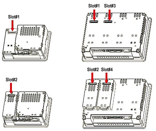
6.6 Connecting plug-in modules
The TX700 HMIs allow the use of several optional in modules. Several module configurations
are possible.
Fig. 15: Slots for plug-in modules
Slot 2 and slot 4 are available only if the plug-in module has bus extension connector.
Each slot has three communication channels:
n 1 serial interface
n 1 CAN interface
n 1 SPI interface
NOTE
It is not possible to stack two modules that are using the same type of interface.
The following table shows, which plug-in module and how many plug-in modules can be used
at which device:
Module Application Max. number of modules Interface type/ Bus extension
communication connector
interface
TX-CAN CAN n 1 for TX705 CAN Yes
TX-RS485 RS485/RS422 n 2 for TX707… TX721 Serial Yes
TX-RS232 RS232 Serial Yes
TX-IO-DX06 Compact I/O SPI No
TX-IO-XX03 Multifunction I/O 1 SPI No
TX705: TX-EXTEND or other
extension module with ex-
tension slot necessary
22 Hans Turck GmbH & Co. KG | T +49 208 4952-0 | F +49 208 4952-264 | more@turck.com | www.turck.comModule Application Max. number of modules Interface type/ Bus extension
communication connector
interface
TX-DP-S PROFIBUS-DP 1 SPI No
slave
TX-UMTS UMTS modem Serial Yes
TX-EXTEND Extension module 1 for TX705 None Yes
The column max. modules refers to the max. number of modules which can be plugged into
the HMI (all slots).
6.6.1 Slot assignment – CAN port
Physical interface CODESYS parameter „network”
Slot 1 Network 0
Slot 2 Network 0
Slot 3 Network 1
Slot 4 Network 1
6.6.2 Slot assignment – serial interfaces
Physical interface CODESYS parameter “Device/In- CODESYS parameter “Modbus
terface Parameter” COM/COM Port”
local serial COM port Mode COM1 COM Port 1
Slot 1 Mode COM2 COM Port 2
Slot 2 Mode COM2 COM Port 2
Slot 3 Mode COM3 COM Port 3
Slot 4 Mode COM3 COM Port 3
Slot 1 to Slot 4 refer to the extension slots on the rear of the device.
V03.00 | 2021/02 23Commissioning
Web server login
7 Commissioning
DANGER
Potentially explosive atmosphere
Explosion due to ignitable sparks in case of electrostatic discharge
For use in zones 2 and 22: Clean the front of the device with a damp cloth before
switching on to prevent electrostatic discharge.
7.1 Charging the battery
The device is equipped with a rechargeable lithium battery, which is not user replaceable.
The following information is maintained by the battery:
n Hardware real-time clock (date and time)
Charge the battery for at least 48 hours before using the device for the first time.
When the battery is fully charged, it guarantees data backup at 25 °C for three months.
7.2 Using the touchscreen
Before initial operation, check that the touch screen is working properly.
Do not use sharp or pointed objects (screwdrivers, etc.) to operate the touch screen.
7.3 Initial commissioning
The Ethernet ports of the device are set to DHCP by default. During the initial commissioning,
the IP address is therefore set via the system settings on the touch screen of the device, via a
DHCP server in the network or via the Turck Service Tool.
7.4 Web server login
Open the web server using the device's IP address.
Connect via https://IP.
IP = current IP address of the TX… device
Log on to the device as administrator:
Default user: admin
Default passwort: admin
If the simple link causes a conflict with an already active WebVisu application, the system set-
tings can also be accessed directly via the following link:
https://IP/machine_config
Example access:
https://192.168.1.24/machine_config
Username: admin
Password: admin
24 Hans Turck GmbH & Co. KG | T +49 208 4952-0 | F +49 208 4952-264 | more@turck.com | www.turck.com7.5 Setting the IP address
The IP address can be set via the system settings on the touch screen of the device, the device’s
web server or via the Turck Service Tool.
7.5.1 Setting the IP address via the web server
Log in to the device’s web server as described under “Web server login”.
Edit the network setting via System Settings Ò Network Ò Edit.
Fig. 16: Webserver – system settings
Set the IP address, the subnet mask, etc. under Network interface and save the changes.
Fig. 17: Webserver – network interface
V03.00 | 2021/02 25Commissioning
Setting the IP address
7.5.2 Setting the IP address via Turck Service Tool
Connect the device to the PC via the Ethernet interface.
Open Turck Service Tool.
Click Search or press [F5].
Fig. 18: Turck Service Tool – home screen
a Turck Service Tool shows the connected devices.
NOTE
Clicking the device's IP address opens the web server.
Fig. 19: Turck Service Tool – found devices
26 Hans Turck GmbH & Co. KG | T +49 208 4952-0 | F +49 208 4952-264 | more@turck.com | www.turck.com Click on the desired device.
Click Change or press [F2].
Change the IP address and the net mask, if necessary.
Accept the changes with Set in device.
Fig. 20: Turck Service Tool – changing the IP configuration
7.6 Programming with CODESYS
The devices are delivered with a pre-installed CODESYS runtime.
The CODESYS software as well as the CODESYS package for the devices can be downloaded
from www.turck.com.
Prerequisites
n CODESYS (≥ V 3.5.14.0) and the package“TXxxx HMI/PLC series” for the device have to be in-
stalled on a PC running Microsoft Windows.
7.7 Programming with TX VisuPro
Prerequisites
n For programming the HMI/PLCs with TX VisuPro, the software tool has to be installed on a PC
computer running Microsoft Windows.
n If the WebVisu of TX VisuPro is to be used instead of the CODESYS-WebVisu, the TX VisuPro-
Runtime must be installed first.
n Before installing TX VisuPro, the existing CODESYS runtime has to be deleted.
To delete the currently installed runtime, run the following command:
System Settings Ò Management Ò Data Ò Clear
7.7.1 Transferring TX VisuPro to the device
There are two options to transfer a TX VisuPro runtime project to a device:
n Via Ethernet
n Via a USB stick
V03.00 | 2021/02 27Commissioning
Programming with TX VisuPro
Project transfer via Ethernet
Connect the HMI device to the computer with an Ethernet network.
Execute the command Run/Download in TX VisuPro. You may have to ensure that the
proper firewall policy has been configured in the computer to allow TX VisuPro to access
the network.
Project transfer via a USB stick
Create an update package with TX VisuPro and copy it to a USB stick.
28 Hans Turck GmbH & Co. KG | T +49 208 4952-0 | F +49 208 4952-264 | more@turck.com | www.turck.com8 Configuring
The devices have an integrated User interface and a web server for configuring the system. The
user interface is based on HTML pages accessible via port 443 using a Web browser (Fire-
fox V.79 Chrome V.44 or higher). Alternatively, the system settings can be called and operated
via a VNC client. To use the VNC client, the VNC service must be activated in the system set-
tings.
Initial commissioning is done by local access to the system settings via the touch screen on the
device. If the "System Settings" button is not displayed on the home screen, the device must be
restarted in "Tap-Tap mode" (see "Recovery operation" in the "Adapting the system set-
tings" [} 29]).
8.1 Configuring the system settings
The available options can be selected from the navigation menu on the left side of the screen.
Fig. 21: System settings
System settings has two operating modes:
Mode Usage
User mode n Device with TX VisuPro runtime
n Device in delivery state
System Mode In addition to the options in user mode, the system mode includes ad-
ditional commands for system upgrade and recovery.
n Device without TX VisuPro runtime
n Device with software error
Edit system settings in user mode
Status device Description
Factory default status Open the system settings.
TX VisuPro runtime Press and hold the unused area of the touch screen for at least
running 2 s.
Open the context menu and select System Settings.
V03.00 | 2021/02 29Setting
Configuring the system settings
Edit the system settings in system mode
Status device Description
Standard If no TX VisuPro runtime is running on the device:
User mode
Open the System Settings.
System Mode
Device without TX VisuPro runtime: Restart the device via
Restart Ò Config. OS.
Device with TX VisuPro runtime: Open the context menu and se-
lect System Settings.
To open the context menu: Press and hold the unused area of
the touch screen for at least 2 s.
Restart the device via Restart Ò Config. OS.
Recovery operation If the device is not responsive, use the so-called “tap-tap” procedure.
Touch the surface of the touch screen several times with a typ-
ing frequency of at least 2 Hz immediately after switching on the
device.
a When the sequence is detected, the message "Tap Tap detected,
Going to Config Mode" will appear on the display.
The basic settings for the device are made in the system settings.
Setting Description
Language Configuration of the language used for the System Settings menu.
System Information about platform, status and timers (“like System on time,
“backlight on time”)
Logs Activating and exporting persistent log for BSP
Date & Time Date and time, including time zone and NTP Server
Network Configuration of the IP address of the Ethernet interface and the other
network settings like DNS, gateway, DHCP, host name, routing and
bridging.
Services Activate/deactivate services (e.g. OpenSSH server, bridge, cloud,
router, SNMP, logging)
Management Update of BSP components (Main OS, Config OS, Boot loader,
XLoader), check for partitions consistence, update of splash screen, in-
formation about usage and size of partitions.
The update of Main OS is available only in System Mode, the update of
Config OS is only in User Mode.
Display Configuring the automatic backlight, adjusting the brightness, chan-
ging the display orientation
Restart Restarts the device
By default, the device is restarted in user mode via the "Main OS" op-
tion. The "Configuration OS" option restarts the device directly in Sys-
tem Settings in system Mode.
Authentication Configuration ot the password for the administrator ("admin") and for
the standard user ("user”). The administrator has full access to the sys-
tem settings (updates of the BSP and other system components). The
standard user has some restrictions.
30 Hans Turck GmbH & Co. KG | T +49 208 4952-0 | F +49 208 4952-264 | more@turck.com | www.turck.com9 Operating
DANGER
Changing components
Explosion hazard – Suitability for Class 1, Division 2 possibly impaired
When replacing components, make sure that the suitability of the device for
Class 1, Division 2 is not affected.
Only use components that are suitable for use in Class 1, Division 2.
If necessary, take measures to restore suitability for Class 1, Division 2.
9.1 LED displays
The device has the following LED displays:
n Status of the Ethernet ports
LED orange (left LED) Meaning
off No Ethernet connection
On Ethernet connection established
LED green (right LED) Meaning
On No data transfer
Blinking Data transfer
V03.00 | 2021/02 31Troubleshooting
10 Troubleshooting
If the device does not function as expected, first check whether ambient interference is present.
If there is no ambient interference present, check the connections of the device for faults.
If there are no faults, there is a device malfunction. In this case, decommission the device and
replace it with a new device of the same type.
32 Hans Turck GmbH & Co. KG | T +49 208 4952-0 | F +49 208 4952-264 | more@turck.com | www.turck.com11 Maintenance
Dust layers on the display can lead to static electricity.
To avoid dust layers on the display: Clean the device at regular intervals with a soft cloth
and a neutral soap product.
Do not use solvents.
12 Repair
The device must not be repaired by the user. The device must be decommissioned if it is faulty.
When returning to Turck, please refer to our return policies.
12.1 Returning devices
Returns to Turck can only be accepted if the device has been equipped with a Decontamination
declaration enclosed. The decontamination declaration can be downloaded from
https://www.turck.de/en/retoure-service-6079.php
and must be completely filled in, and affixed securely and weather-proof to the outside of the
packaging.
13 Disposal
The device is equipped with a rechargeable lithium battery, which is not user replaceable.
For disposal, open the back of the device and remove the battery.
The device the lithium battery must be disposed of properly in accordance with
WEEE Directive 2012/19/EU and does not belong in normal household waste.
V03.00 | 2021/02 33Technical Data
14 Technical Data
TX705-P3CV01 TX707-P3CV01
Device
Ident no. 100002029 100002030
Display/touch
Display TFT color TFT color
Touch Capacitive Capacitive
Active image area 5" 7"
Resolution (pixels) 800 × 480 800 × 480
Format 16:9 16:9
Brightness 300 Cd/m² typ. 500 Cd/m² typ.
Dimmable Yes (up to 0 %) Yes (up to 0 %)
Viewing angle horizontal n From the right 50° 70°
n From the left: 70°
Viewing angle vertical 70° n From above: 50°
n From below: 70°
System
CPU ARM Cortex-A8, ARM Cortex-A9,
single core 1 GHz dual core 800 MHz
Operating system Linux RT Linux RT
Flash 4 GB 4 GB
RAM 1 GB 1 GB
Expansion memory USB/SD card USB/SD card
Real Time Clock Yes (battery-backed) Yes (battery-backed)
Accuracy RTC < 100 ppm < 100 ppm
(at 25 °C)
Buzzer Yes Yes
SPS data
Programming CODESYS V3 CODESYS V3
Programming languages IEC 61131-3 IEC 61131-3
(IL, LD, FBD, SFC, ST) (IL, LD, FBD, SFC, ST)
Programming interface Ethernet Ethernet
Program memory 20 MB 20 MB
Non-volatile memory 63 kByte 63 kByte
Interfaces
Ethernet ports 2 × 10/100 Mbit 1 × 10/100/1000 Mbit
2 × 10/100 Mbit
Serial ports (configurable) 1 × RS232/RS485/RS422 1 × RS232/RS485/RS422
USB Host port 1 × V2.0, 2 × V2.0,
max. 500 mA max. 500 mA
SD card Yes Yes
Extension slot (plug-in) 1 2
n Max. number of 2 4
plug-in modules
34 Hans Turck GmbH & Co. KG | T +49 208 4952-0 | F +49 208 4952-264 | more@turck.com | www.turck.comTX705-P3CV01 TX707-P3CV01
Power supply
Rated value 24 VDC 24 VDC
(SELV or Class 2) (SELV or Class 2)
Admissible voltage range 18…32 VDC 18…32 VDC
Current consumption at 24 VDC 0.6 A 0.7 A
Dimensions
Housing (W × H) 147 × 107 mm 187 × 147 mm
Installation cut-out (W × H) 136 × 96 mm 176 × 136 mm
Installation depth (D) 52 mm 47 mm
Weight 0.8 kg 1.1 kg
TX710-P3CV01 TX715-P3CV01 TX721-P3CV01
Device
Ident no. 100002031 100002032 100002033
Display/touch
Display TFT color TFT color TFT color
Touch Capacitive Capacitive Capacitive
Active image area 10.1" 15.6" 21.1"
Resolution (pixels) 1280 × 800 1366 × 768 1920 × 1080
Format 16:9 16:9 16:9
Brightness 500 Cd/m² typ. 400 Cd/m² typ. 300 Cd/m² typ.
Dimmable Yes Yes Yes
Viewing angle horizontal 85° 80° 89°
Viewing angle vertical 85° 80° 89°
System
CPU ARM Cortex-A9, ARM Cortex-A9, ARM Cortex-A9,
dual core 800 MHz quad core 800 MHz quad core 800 MHz
Operating system Linux RT Linux RT Linux RT
Flash 4 GB 8 GB 8 GB
RAM 1 GB 2 GB 2 GB
Expansion memory USB/SD card USB/SD card USB/SD card
Real Time Clock Yes (battery-backed) Yes (battery-backed) Yes (battery-backed)
Accuracy RTC < 100 ppm < 100 ppm < 100 ppm
(at 25 °C)
Buzzer Yes Yes Yes
SPS data
Programming CODESYS V3 CODESYS V3 CODESYS V3
Programming languages IEC 61131-3 IEC 61131-3 IEC 61131-3
(IL, LD, FBD, SFC, ST) (IL, LD, FBD, SFC, ST) (IL, LD, FBD, SFC, ST)
Programming interface Ethernet Ethernet Ethernet
Program memory 20 MB 20 MB 20 MB
Non-volatile memory 63 kByte 63 kByte 63 kByte
Interfaces
V03.00 | 2021/02 35Technical Data
TX710-P3CV01 TX715-P3CV01 TX721-P3CV01
Ethernet ports 1 × 10/100/1000 Mbit 1 × 10/100/1000 Mbit 1 × 10/100/1000 Mbit
2 × 10/100 Mbit 2 × 10/100 Mbit 2 × 10/100 Mbit
Serial ports (configurable) 1 × RS232/RS485/RS422 1 × RS232/RS485/RS422 1 × RS232/RS485/RS422
USB Host port 2 × V2.0, 2 × V2.0, 2 × V2.0,
max. 500 mA max. 500 mA max. 500 mA
SD card Yes Yes Yes
Extension slot (plug-in) 2 2 2
n Max. number of plug-in mod- 4 4 4
ules
Power supply
Rated value 24 VDC (SELV or Class 2) 24 VDC (SELV or Class 2) 24 VDC (SELV or Class 2)
Admissible voltage range 18…32 VDC 18…32 VDC 18…32 VDC
Current consumption at 24 VDC 1 A 1.2 A 1.7 A
Dimensions
Housing (W × H) 282 × 197 mm 422 × 267 mm 552 × 347 mm
Installation cut-out (W × H) 271 × 186 mm 411 × 256 mm 541 × 336 mm
Installation depth (D) 56 mm 56 mm 56 mm
Weight 1.8 kg 3.5 kg 6.1 kg
TX707HB-P3CV01 TX710HB-P3CV01
Device
Ident no. 100007473 100007474
Display/touch
Display TFT color TFT color
Touch Capacitive Capacitive
Active image area 7" 10.1"
Resolution (pixels) 800 × 480 1280 × 800
Format 16:9 16:9
Brightness 600 Cd/m² 800 Cd/m² typ.
Dimmable Yes (up to 0 %) Yes (up to 0 %)
Viewing angle horizontal 70 ° 85°
Viewing angle vertical n From above: 50° 85°
n From below: 60°
System
CPU ARM Cortex-A9, ARM Cortex-A9,
dual core, 800 MHz dual core, 800 MHz
Operating system Linux RT Linux RT
Flash 4 GB 4 GB
RAM 1 GB 1 GB
Expansion memory USB/SD card USB/SD card
Real Time Clock Yes (battery-backed) Yes (battery-backed)
Accuracy RTC < 100 ppm < 100 ppm
(at 25 °C)
Buzzer Yes Yes
36 Hans Turck GmbH & Co. KG | T +49 208 4952-0 | F +49 208 4952-264 | more@turck.com | www.turck.comTX707HB-P3CV01 TX710HB-P3CV01
SPS data
Programming CODESYS V3 CODESYS V3
Programming languages IEC 61131-3 IEC 61131-3
(IL, LD, FBD, SFC, ST) (IL, LD, FBD, SFC, ST)
Programming interface Ethernet Ethernet
Program memory 20 MB 20 MB
Non-volatile memory 63 kByte 63 kByte
Interfaces
Ethernet ports 1 × 10/100/1000 Mbit 1 × 10/100/1000 Mbit
2 × 10/100 Mbit 2 × 10/100 Mbit
Serial ports (configurable) 1 × RS232/RS485/RS422 1 × RS232/RS485/RS422
USB Host port 2 × V2.0, 2 × V2.0,
max. 500 mA max. 500 mA
SD card Yes Yes
Extension slot (plug-in) 2 2
n Max. number of plug-in mod- 4 4
ules
Power supply
Rated value 24 VDC 24 VDC
(SELV or Class 2) (SELV or Class 2)
Admissible voltage range 18…32 VDC 18…32 VDC
Current consumption at 24 VDC Max. 0.7 A Max. 1.0 A
Dimensions
Housing (W × H) 187 × 147 mm 282 × 197 mm
Installation cut-out (W × H) 176 × 136 mm 271 × 168 mm
Installation depth (D) 47 + 8 mm 56 + 8 mm
Weight 1.5 kg 2.5 kg
NOTE
For applications requiring compliance with EN 61131-2 and specifically in reference
to 10 ms voltage dips, the minimum power supply voltage is 18 VDC.
Protection class according to EN 60529
Device front IP66
Device rear IP20
V03.00 | 2021/02 37Technical Data
Environmental conditions
Operating temperature (sur- -20…+60 °C (vertical installation) EN 60068- 2- 14
rounding air temperature) Plug-in modules and USB devices may
limit the maximum temperature to
+50 °C
Storage temperature -20…+70 °C EN 60068-2-1
EN 60068-2-2
EN 60068-2-14
Operating and storage humidity 5…85 % RH, EN 60068-2-30
non condensing
Vibrations 5…9 Hz, 7 mmp-p EN 60068-2-6
9…150 Hz, 1 g
Shock ± 50 g, 11 ms, EN 60068-2-27
3 pulses per axis
Electromagnetic Compatibility (EMC)
Radiation interference Class A CISPR 22,
CISPR 16-2-3
Immunity EN 61000-4-2
Electrostatic discharge 8 kV (air electrostatic discharge)
4 kV (contact electrostatic discharge)
Radiation, high frequency, elec- 80 MHz …1 GHz, 10 V/m EN 61000-4-3
tromagnetic fields 1.4 GHz … 2 GHz, 3 V/m
2 GHz … 2.7 GHz, 1 V/m
Burst ± 2 kV DC power port EN 61000-4-4
± 1 kV signal line
Overvoltage ± 0.5 kV DC power port (line to earth) EN 61000-4-5
± 0.5 kV DC power port (line to line)
± 1 kV signal line (line to earth)
Interference from high-fre- 0.15…80 MHz, 1 V EN 61000-4-6
quency fields
Power frequency magnetic field Housing: 50/60Hz, 30A/m EN 61000-4-8
immunity test
Voltage dips, short interruptions, Port: AC mains; Level:
voltage fluctuations 100 % duration: 1 cycle and 250 cycles (50 Hz)
40 % duration: 10 cycles (50 Hz)
70 % duration: 25 cycles (50 Hz)
phase: 0°…180°
Test executed on the 230 VAC side of the power supply EN 61000-4-11
Port: DC mains 0 %
duration: 10 ms 20 fields × 1 s
Test executed on the 24 VDC of the EUT EN 61000-4-29
38 Hans Turck GmbH & Co. KG | T +49 208 4952-0 | F +49 208 4952-264 | more@turck.com | www.turck.comDisplay durability
Backlight service life
Durability at 25 °C, continuous Time to darken the display to min. 40000 hours (LED type)
operation 50 % of the nominal value
NOTE
Prolonged use at an ambient temperature of 40 °C or higher may result in a deterior-
ation in the quality, reliability and durability of the backlight.
Display viewing angles
The viewing angles are included in the technical data of the respective device and are specified
for the horizontal and vertical axis in relation to the vertical axis of the display. The specified
angles always refer to the standard mounting orientation (landscape format).
Fig. 22: Viewing angle
Viewing angle
U From the top
D From the bottom
L From the left
R From the right
V03.00 | 2021/02 39Appendix
15 Appendix: Approvals and markings
Approvals Marking according to EN 60079-0/-15/-31
ATEX directive
ATEX approval no.: ÉII 3 G Ex nA IIC T5…T4 Gc
DEMKO 20 ATEX 2333X ÉII 3 D Ex tc IIIC T95°C Dc
IECEx approval no.: Ex nA IIC T5…T4 Gc
IECEx ULD 20.0001X Ex tc IIIC T95°C Dc
Ambient temperature Tamb.: 0…+50 °C or -20…+60 °C,
for mounting on the flat surface of a housing of type 12, 4X
Max. ambient temperature Temperature Class
-20…+60 °C T4
0…+50 °C T5
Approvals
Immunity/emission
n For industrial environments:
EN 61000-6-2
EN 61000-6-4
n For residential, business and commercial areas and small
businesses:
EN 61000-6-1
EN 61000-6-3
n For marine environments:
EN 60945
EN 61000-4-29
EN 60079-0
EN 6007915
EN 6007931
UL cULus (UL File No. E484727)
n UL 61010-1, 3rd Edition and UL 61010-2-201, 1st Edition
n CAN/CSA C22.2 No. 61010-1, 3rd Edition and
CAN/CSA C22.2 No. 61010-2-201:14
cULus (UL File No. E484803)
n Class I, Division 2, Groups A, B, C and D
DNV-GL Yes
LR (not for TX707HB and TX710HB)
40 Hans Turck GmbH & Co. KG | T +49 208 4952-0 | F +49 208 4952-264 | more@turck.com | www.turck.comOver 30 subsidiaries and over
60 representations worldwide!
100002669 | 2021/02
100002669 www.turck.comYou can also read