2021 LEAF
Roadside Assistance Guide
←
→
Page content transcription
If your browser does not render page correctly, please read the page content below
2021 LEAF Roadside Assistance Guide
Foreword

This manual describes roadside assistance operations and important safety related warnings for this
vehicle.
This vehicle is an electrically driven car equipped with a high-voltage battery pack. Failure to follow
recommended practices during emergency responses will cause death or serious personal
injury.
Please read this manual in advance in order to understand the features of this vehicle and to help you deal
with roadside assistance operations involving this vehicle. Follow the procedures in order to help assure
a safe and successful roadside assistance operation.
This manual is periodically updated. If you are not viewing this manual on the Nissan web site, we urge you
to go to www.nissanusa.com or www.nissan-techinfo.com to make sure you have the most recent version of
this manual.

NISSAN EMERGENCY CONTACT INFORMATION
     • Nissan EV Customer Support: 1-877-664-2738
     • Nissan Consumer Affairs: 1-800-647-7261 (US) or 1-800-387-0122 (Canada)

IMPORTANT INFORMATION ABOUT THIS MANUAL
You may see various symbols in this manual. They have the following meanings:

This symbol is used to inform you of an operation which will result in death or serious personal injury if
instructions are not followed.
Example: Touching high-voltage components without using the appropriate protective equipment will result
in electrocution.

This symbol is used to inform you of an operation which may cause death or serious personal injury if
instructions are not followed.

This symbol is used to inform you of an operation which may cause personal injury or component damage if
instructions are not followed.

Please note that there may be differences between this manual and the vehicle specification due to
specification changes.

RAG–2
Table of Contents
FOREWORD . . . . . . . . . . . . . . . . . . . . . . . . . . . . . . . . . . . . . . . . . . . . . . . . . . . . . . . . . . . . . . . . . . RAG–2
     NISSAN EMERGENCY CONTACT INFORMATION . . . . . . . . . . . . . . . . . . . . . . . . . . . . . . . . . . RAG–2
     IMPORTANT INFORMATION ABOUT THIS MANUAL . . . . . . . . . . . . . . . . . . . . . . . . . . . . . . . . RAG–2
1. ABOUT THE NISSAN LEAF® . . . . . . . . . . . . . . . . . . . . . . . . . . . . . . . . . . . . . . . . . . . . . . . . . . . RAG–5
     1-1 LEAF IDENTIFICATION . . . . . . . . . . . . . . . . . . . . . . . . . . . . . . . . . . . . . . . . . . . . . . . . . . . . RAG–6
          1-1.1 EXTERIOR . . . . . . . . . . . . . . . . . . . . . . . . . . . . . . . . . . . . . . . . . . . . . . . . . . . . . . . . . RAG–6
          1-1.2 INTERIOR COMPONENT LOCATION                               . . . . . . . . . . . . . . . . . . . . . . . . . . . . . . . . . . . RAG–7
          1-1.3 VEHICLE IDENTIFICATION NUMBER (VIN) LAYOUT . . . . . . . . . . . . . . . . . . . . . . . . RAG–8
          1-1.4 WARNING AND INDICATOR LAMP INFORMATION . . . . . . . . . . . . . . . . . . . . . . . . RAG–9
2. BASIC HIGH-VOLTAGE INFORMATION . . . . . . . . . . . . . . . . . . . . . . . . . . . . . . . . . . . . . . . . . . RAG–10
     2-1 HIGH-VOLTAGE-RELATED AND 12-VOLT-RELATED COMPONENT LOCATIONS
         AND DESCRIPTIONS . . . . . . . . . . . . . . . . . . . . . . . . . . . . . . . . . . . . . . . . . . . . . . . . . . . . RAG–10
          2-1.1 HIGH-VOLTAGE BATTERY PACK SPECIFICATIONS . . . . . . . . . . . . . . . . . . . . . . RAG–12
     2-2 HIGH-VOLTAGE SAFETY MEASURES . . . . . . . . . . . . . . . . . . . . . . . . . . . . . . . . . . . . . . RAG–12
          2-2.1 WARNING LABELS . . . . . . . . . . . . . . . . . . . . . . . . . . . . . . . . . . . . . . . . . . . . . . . . RAG–12
3. ROADSIDE ASSISTANCE RESPONSE STEPS . . . . . . . . . . . . . . . . . . . . . . . . . . . . . . . . . . . . RAG–14
     3-1 INDICATIONS THE HIGH-VOLTAGE SYSTEM IS ON . . . . . . . . . . . . . . . . . . . . . . . . . . . RAG–14
     3-2 VEHICLE IMMOBILIZATION AND STABILIZATION . . . . . . . . . . . . . . . . . . . . . . . . . . . . . . RAG–15
     3-3 TURNING OFF THE POWER SWITCH . . . . . . . . . . . . . . . . . . . . . . . . . . . . . . . . . . . . . . RAG–16
     3-4 WATER SUBMERSION . . . . . . . . . . . . . . . . . . . . . . . . . . . . . . . . . . . . . . . . . . . . . . . . . . . RAG–16
     3-5 VEHICLE FIRE . . . . . . . . . . . . . . . . . . . . . . . . . . . . . . . . . . . . . . . . . . . . . . . . . . . . . . . . . . RAG–17
     3-6 HIGH-VOLTAGE BATTERY DAMAGE AND FLUID LEAKS . . . . . . . . . . . . . . . . . . . . . . . . RAG–18
4. ROADSIDE ASSISTANCE . . . . . . . . . . . . . . . . . . . . . . . . . . . . . . . . . . . . . . . . . . . . . . . . . . . . . RAG–19
     4-1 JUMP STARTING . . . . . . . . . . . . . . . . . . . . . . . . . . . . . . . . . . . . . . . . . . . . . . . . . . . . . . . RAG–19
          4-1.1 JUMP STARTING PROCEDURES                             . . . . . . . . . . . . . . . . . . . . . . . . . . . . . . . . . . . . . RAG–20
     4-2 ELECTRIC PARKING BRAKE RELEASE PROCEDURES . . . . . . . . . . . . . . . . . . . . . . . . . RAG–21
          4-2.1 RELEASING ELECTRIC PARKING BRAKE USING PARKING BRAKE SWITCH . . . RAG–21
          4-2.2 RELEASING ELECTRIC PARKING BRAKE WHERE PARKING BRAKE SWITCH
                CANNOT BE USED . . . . . . . . . . . . . . . . . . . . . . . . . . . . . . . . . . . . . . . . . . . . . . . . RAG–22
     4-3 P (PARK) POSITION RELEASE PROCEDURE . . . . . . . . . . . . . . . . . . . . . . . . . . . . . . . . . RAG–23
          4-3.1 RESET PROCEDURE . . . . . . . . . . . . . . . . . . . . . . . . . . . . . . . . . . . . . . . . . . . . . . . RAG–23

                                                                                                                                         RAG–3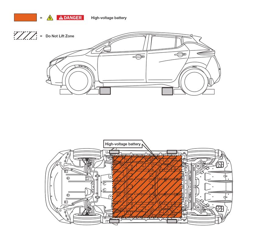
4-4 TOWING . . . . . . . . . . . . . . . . . . . . . . . . . . . . . . . . . . . . . . . . . . . . . . . . . . . . . . . . . . . . . . RAG–24
         4-4.1 VEHICLE SPECIFICATIONS . . . . . . . . . . . . . . . . . . . . . . . . . . . . . . . . . . . . . . . . . . RAG–24
         4-4.2 TOWING GUIDELINES . . . . . . . . . . . . . . . . . . . . . . . . . . . . . . . . . . . . . . . . . . . . . . RAG–24
         4-4.3 USE OF VEHICLE EQUIPPED HOOKS FOR RECOVERY OPERATIONS . . . . . . . RAG–25
    4-5 STORING THE VEHICLE . . . . . . . . . . . . . . . . . . . . . . . . . . . . . . . . . . . . . . . . . . . . . . . . . RAG–26
    4-6 JACKING UP THE VEHICLE AND CHANGING A TIRE . . . . . . . . . . . . . . . . . . . . . . . . . . RAG–26
    4-7 REPAIRING A FLAT TIRE WITH NISSAN EMERGENCY TIRE PUNCTURE REPAIR KIT . . . RAG–27
         4-7.1 BEFORE USING EMERGENCY TIRE PUNCTURE REPAIR KIT . . . . . . . . . . . . . . . RAG–28
         4-7.2 REPAIRING THE TIRE . . . . . . . . . . . . . . . . . . . . . . . . . . . . . . . . . . . . . . . . . . . . . . . RAG–29
         4-7.3 AFTER REPAIRING THE TIRE . . . . . . . . . . . . . . . . . . . . . . . . . . . . . . . . . . . . . . . . . RAG–31
5. STORING THE VEHICLE . . . . . . . . . . . . . . . . . . . . . . . . . . . . . . . . . . . . . . . . . . . . . . . . . . . . . . RAG–32
    5-1 DANGER SIGN EXAMPLE . . . . . . . . . . . . . . . . . . . . . . . . . . . . . . . . . . . . . . . . . . . . . . . . RAG–33
    5-2 PREPARATION ITEMS . . . . . . . . . . . . . . . . . . . . . . . . . . . . . . . . . . . . . . . . . . . . . . . . . . . RAG–34
         5-2.1 PERSONAL PROTECTIVE EQUIPMENT (PPE) PROTECTIVE WEAR CONTROL . . . RAG–34
         5-2.2 DAILY INSPECTION . . . . . . . . . . . . . . . . . . . . . . . . . . . . . . . . . . . . . . . . . . . . . . . . RAG–35
         5-2.3 INSULATED TOOLS . . . . . . . . . . . . . . . . . . . . . . . . . . . . . . . . . . . . . . . . . . . . . . . . RAG–35
    5-3 REMOVING THE SERVICE PLUG . . . . . . . . . . . . . . . . . . . . . . . . . . . . . . . . . . . . . . . . . . RAG–35

RAG–4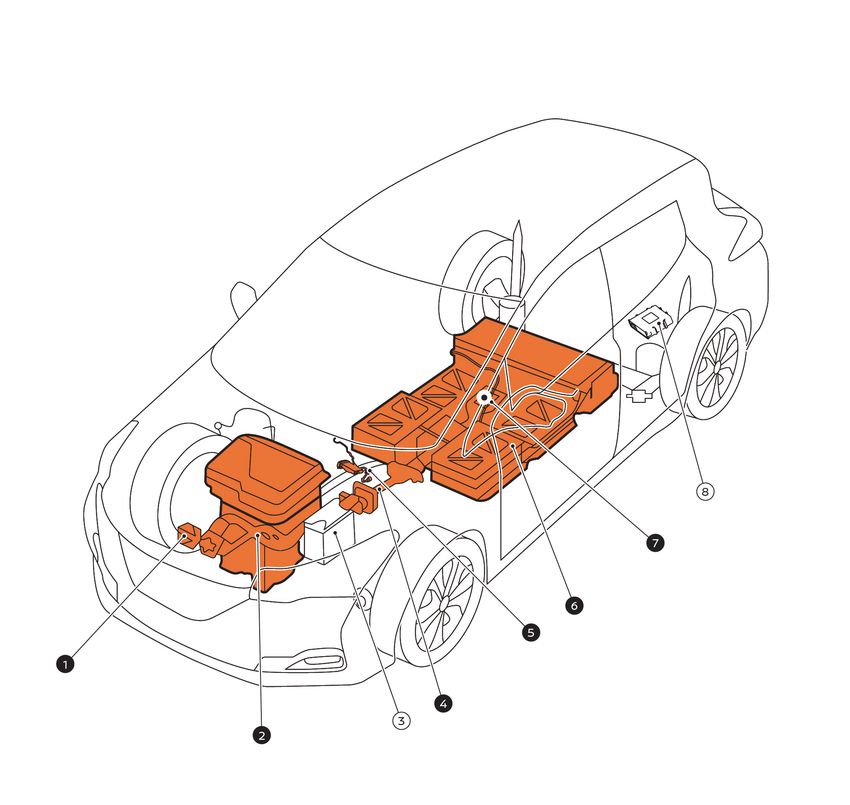
1. About The Nissan LEAF®

This vehicle uses two types of batteries. One is a 12-volt battery that is the same as the battery in vehicles
powered by internal combustion engines, and the other is the high-voltage battery for the traction motor
which propels the vehicle. The high-voltage battery is encased in steel and mounted underneath the vehicle.
The vehicle must be plugged-in in order for the high-voltage battery to be recharged. Additionally, the
vehicle system can recharge the high-voltage battery by converting driving force into electricity while the
vehicle is decelerating or being driven downhill. This is called regenerative charging. This vehicle is
considered to be an environmentally friendly vehicle because it does not emit exhaust gases.

                                                                                                       RAG–5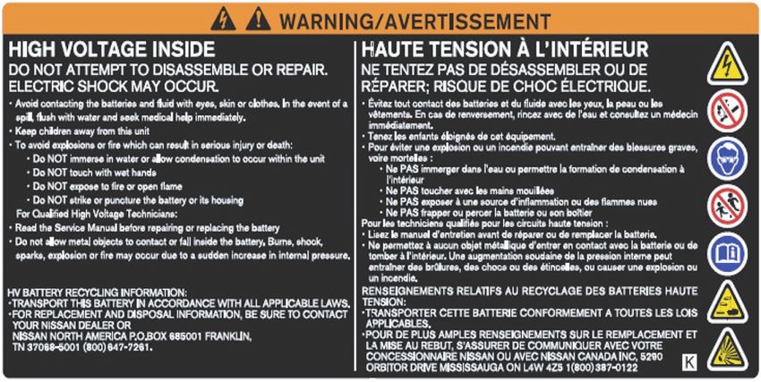
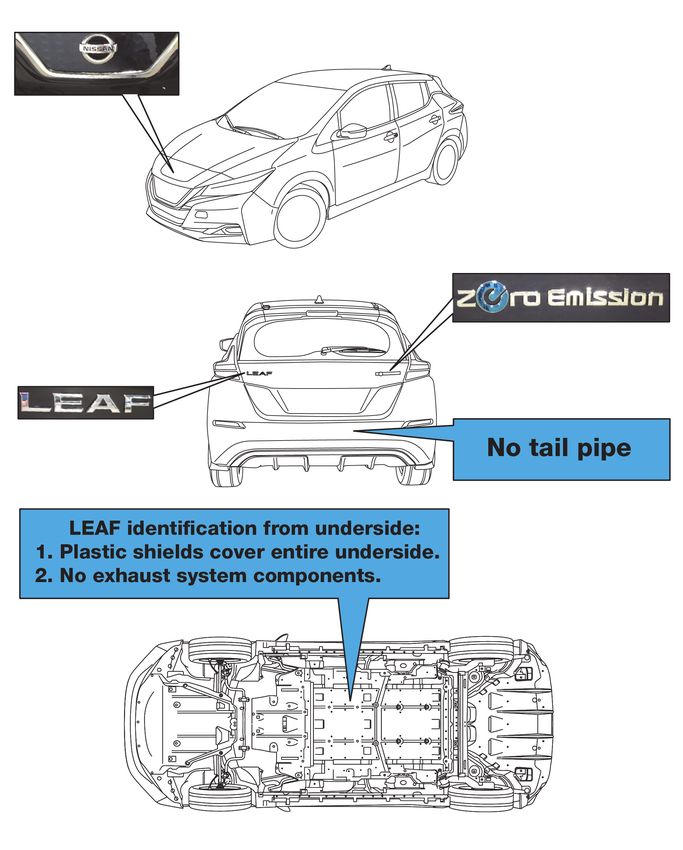
1-1 LEAF Identification

1-1.1 Exterior

The specific exterior identification features are indicated as follows:

                                                                          TGAAYIA0082GB

RAG–6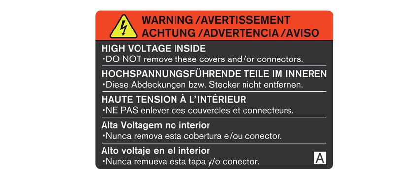
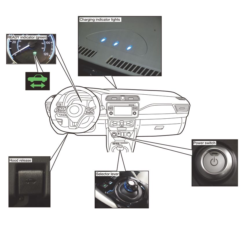
1-1.2 Interior Component Location
Interior components referenced in this manual are as follows:

                                                                TGAAYIA0015GB

                                                                      RAG–7
1-1.3 Vehicle Identification Number (VIN) Layout
The vehicle identification number can be located as follows: Example VIN : 1N4A/BZ1CPXMC053500
The High-voltage battery type is identified by the 4th alphanumeric character: A or B
A = 40 kWh Battery
B = 62 kWh Battery
The LEAF is identified by the 5th alphanumeric character: Z
Z = Electric vehicle

                                                                                                  TGAAYIA0067ZZ

1. VIN plate (visible through windshield)           2. Vehicle certification label (lower center pillar)

RAG–8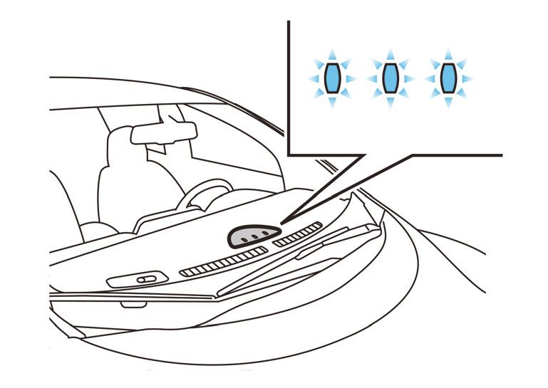
1-1.4 Warning and Indicator Lamp Information
The following warning and indicator lamps are located in the instrument cluster.
        Lamp Name                   Icon                               Description
READY Indicator                               This lamp is on when the EV system is powered up and the
                                              vehicle is ready to drive.

EV System Warning Lamp*1                      • Malfunction has occurred in the EV system and/or
                                              • Emergency shut-off system has been activated.
                                                The shut-off system activates in the following conditions:
                                                – Front and side collisions in which the air bags are
                                                  deployed.
                                                – Certain rear collisions.
                                                – Certain EV system malfunctions.
Master Warning Lamp (RED)                     This lamp is on when another red warning lamp is displayed in
                                              the instrument cluster or a warning is displayed on the vehicle
                                              information display.

Master Warning Lamp                           This lamp is on when:
(YELLOW)                                      • High-voltage battery is getting low on charge.
                                              • A yellow warning lamp is displayed in the instrument cluster
                                                or a message is displayed on the vehicle information
                                                display.

*1: The READY indicator light will turn off in certain EV system malfunctions.

                                                                                                      RAG–9
2. Basic High-Voltage Information

2-1 High-Voltage-Related and 12-volt-Related Component Locations and
Descriptions

                                                                            TGAAYIA0115ZZ

NOTE:

  Components with white number in black background are high-voltage components.

RAG–10
No. Component Location Description
➊ Charge port Under hood Connecting port for EVSE (Electric Vehicle
Supply Equipment). Two ports are available:
Normal charge and quick charge (if so equipped).
➋ Traction Motor Under hood Converts three-phase AC power to drive power
(torque) which propels the vehicle.
Inverter Under hood Converts the DC power stored in the high-voltage
battery to three-phase AC power and controls
motor torque (revolution) by regulating the motor
current.
Electric air Under hood Air conditioner compressor
conditioner
compressor
Power Delivery Under hood The PDM includes an On Board Charger, DC/DC
Module (PDM) converter and high-voltage junction box (J/B).
• On Board Charger The On Board Charger converts single-phase AC
• DC/DC Converter power from a home power outlet to DC power
• High-voltage and increases the voltage in order to charge the
junction box (J/B) high-voltage battery.
The DC/DC converter reduces the voltage of the
high-voltage battery to provide power to the
12-volt battery in order to operate the vehicle’s
electric components (headlights, audio system,
etc.).
The J/B provides electric power from the high-
voltage battery to all high-voltage parts of the
vehicle.
➂ 12-volt Battery Under hood A lead-acid battery that supplies power to the low
voltage devices.
➍ High-voltage cables Under hood and Orange-colored power cables carry high-voltage
undercarriage current between each of the high-voltage
components.
➎ Cabin heater Interior (This unit is This is the electric heat source for the cabin
installed behind the heater. It heats the interior of the vehicle.
instrument panel)
➏ High-voltage battery Undercarriage Stores and outputs DC power (Maximum voltage
420V) needed to propel the vehicle.
➐ High-voltage battery Rear seat floor Isolates the battery from the rest of the high-
service disconnect voltage electrical system.
➇ Brake power supply Cargo area (This unit Power supply backup unit for the brake system.
backup unit is installed behind a It supplies power to the brake system if a
trim panel to prevent malfunction occurs in the 12-volt battery.
access)
RAG–112-1.1 High-Voltage Battery Pack Specifications
High-voltage battery voltage (240V - 420V usable range)
Number of high-voltage battery modules in the pack 24
High-voltage battery dimensions 60.90 x 46.77 x 10.39 in. (1547 x 1188 x 264 mm)
High-voltage battery weight 668.1 lbs (303 kg)
2-2 High-Voltage Safety Measures
Circuit insulation The high-voltage positive (+) and negative (-) circuits are insulated
from the metal chassis.
Reducing the risk of electrocution The high-voltage components and harnesses have insulated cases
or orange-colored coverings which provide insulation and easy
identification.
The high-voltage battery case is electrically connected to the vehicle
ground. This connection helps protect the vehicle occupants and
emergency responders from high-voltage electrical shock.
Identification The high-voltage components are labeled “WARNING” similar to the
label shown below. All high-voltage harnesses are coated in orange.
2-2.1 Warning Labels
The following warning label is applied to the power delivery module (PDM) located under hood.
TGAAYIA0055ZZ
RAG–12The following warning label is applied to the service plug access cover located in the rear seat floor.
AAYIA0455ZZ
The following warning label is applied to the high-voltage battery located on the vehicle’s undercarriage.
AAYIA0456ZZ
RAG–133. Roadside Assistance Response Steps
• NEVER assume the LEAF is shut OFF simply because it is quiet.
• If the vehicle is damaged and you are not sure about the condition of the electric
vehicle system, contact first responders immediately. If the vehicle is damaged, the
high-voltage system should be shut down by first responders while following the
procedures in the First Responder’s Guide and while wearing appropriate Personal
Protective Equipment (PPE).
• If the READY indicator or charging indicator are ON, the high-voltage system is
active.
• If possible, be sure to verify that the READY indicator on the instrument cluster is
OFF and the high-voltage system is stopped.
• Some of the under hood parts get hot and may cause serious burns. Use caution when
working on or around these parts.
3-1 Indications the High-voltage System is ON
1. If the READY indicator is ON, the high-voltage system is active.
2. The high-voltage system is active if any charge indicator
is ON (blue LEDs on top of the instrument panel).
TGAAYIA0026ZZ
Before disconnecting the 12-volt battery terminal, if necessary, lower the windows, unlock the doors, and
open the rear hatch as required. Once 12-volt battery is disconnected, power controls will not operate.
RAG–143-2 Vehicle Immobilization and Stabilization
If possible, immobilize the vehicle by turning the 12V system OFF and stabilize it with a wheel chock(s).
Stabilize the vehicle with wooden blocks or by removing air from the tires.
• Do not stabilize the vehicle with wooden blocks under the high-voltage battery.
• To avoid electrical shock, do not put wooden blocks or wheel chock(s) under the
high-voltage components and harnesses as shown following.
TGAAYIA0013GB
RAG–153-3 Turning OFF the Power Switch
1. Check the READY indicator status. If it is ON, the high-voltage system is active.
2. Press the power switch once to turn OFF the high-
voltage system. Then verify whether the READY
indicator is OFF.
AAYIA0091ZZ
3. If possible, keep the Nissan Intelligent Key® at least
5 meters (16 feet) away from the vehicle to prevent
accidentally turning ON the EV system while the
roadside assistance is in progress.
TGAAYIA0012GB
3-4 Water Submersion
Damage level of submerged vehicle may not be apparent. Handling a submerged
vehicle without appropriate Personal Protective Equipment (PPE) will result in serious
injury or death from electrical shock.
• The power switch of the submerged vehicle must be turned OFF first, if possible.
Then the vehicle must be completely out of the water and drained to avoid electrical
shock.
• If the vehicle is in the water, to avoid electrical shock NEVER touch the high-
voltage components, harnesses or service plug. PPE must always be worn when
touching or working on high-voltage components.
Only first responders wearing appropriate Personal Protective Equipment (PPE) should shut down
the vehicle. After shut down, standard towing/recovery procedures can be used. Refer to 4-4 Towing
(RAG–24) .
RAG–163-5 Vehicle Fire
• Always utilize full Personal Protective Equipment (PPE) and self-contained breathing
apparatus during fire fighting operations. Smoke from a LEAF vehicle fire is similar to
smoke from a conventional vehicle fire.
• In the case of extinguishing a fire with water, large amounts of water from a fire
hydrant (if possible) must be used. DO NOT extinguish fire with a small amount of
water.
In the event of a small fire, a Type ABC fire extinguisher may be used for an electrical fire
caused by wiring harnesses, electrical components, etc. or oil fire.
In case of vehicle fire, contact fire department immediately and extinguish the fire if possible. If you must
walk away from the vehicle, notify an appropriate responder or a rescue person of the fact that the vehicle
is an electric car and contains a high-voltage system and warn all others.
RAG–173-6 High-voltage Battery Damage and Fluid Leaks
The high-voltage battery contains electrolyte solution. To avoid exposure to electrolyte
solution and serious personal injury, always wear appropriate solvent resistant Personal
Protective Equipment (PPE) and read the following precautions:
• Electrolyte solution is a skin irritant – If contact with skin, rinse with plenty of water and
see a doctor immediately.
• Electrolyte solution is an eye irritant – If contact with eyes, rinse with plenty of water and
see a doctor immediately.
• If electrolyte leak occurs, wear appropriate solvent resistant PPE and use a dry cloth to
clean up the spilled electrolyte. Be sure to adequately ventilate the area.
• Electrolyte solution is highly flammable.
• Electrolyte liquid or fumes that have come into contact with water vapors in the air will
create an oxidized substance. This substance may irritate skin and eyes. In these cases,
rinse with plenty of water and see a doctor immediately.
• Electrolyte fumes (when inhaled) can cause respiratory irritation and acute intoxication.
Move to fresh air and wash mouth with water. See a doctor immediately.
In cases of battery case breach or electrolyte leakage, contact the fire department immediately. If you must
walk away from the vehicle, notify an appropriate responder of the fact that the vehicle is an electric car and
contains a high-voltage system and warn all others.
High-voltage Battery Electrolyte Solution Characteristics:
• Clear in color
• Sweet odor
• Similar viscosity to water
• Since the high-voltage battery is made up of many small sealed battery modules, electrolyte solution
leakage should be minimal.
NOTE:
Other fluids in the vehicle are the same as those in a conventional internal combustion
vehicle.
RAG–184. Roadside Assistance
4-1 Jump Starting
To start the EV system with a booster battery, the instructions and precautions below must be followed.
If done incorrectly, jump starting can lead to a 12-volt battery explosion, resulting in severe
personal injury or death. It could also damage your vehicle.
Discharged 12-volt battery may cause the following issues:
• The instrument cluster cannot be displayed while the power switch is turned ON. The start-up
sound is not audible. (The electric car system cannot start.)
• The high-voltage battery cannot be charged.
• The vehicle cannot be shifted out of PARK normally.
• To avoid electrical shock, the high-voltage battery CANNOT be jump started.
• Explosive hydrogen gas is always present in the vicinity of the 12-volt battery. Keep all
sparks and flames away from the 12-volt battery. Make sure the vent tube is correctly
installed.
• Do not allow battery fluid to come into contact with eyes, skin, clothing or painted
surfaces. Battery fluid is a corrosive sulfuric acid solution that can cause severe burns.
If the fluid comes into contact with anything, immediately flush the contacted area
with water.
• The booster battery must be rated at 12 volts. Use of an improperly rated battery can
damage the vehicle.
• Whenever working on or near a 12-volt battery, always wear suitable eye protectors
(for example, goggles or industrial safety spectacles) and remove rings, metal bands,
or any other jewelry. Do not lean over the 12-volt battery when jump starting.
• Do not attempt to jump start a frozen battery. It could explode and cause serious injury.
• LEAF is equipped with an automatic cooling fan. It could come on at any time. Keep
hands and other objects away from it.
• Always follow the jump starting instructions below. Failure to do so could result in
damage to the charging system and cause personal injury.
• Do not use LEAF to jump start another vehicle.
• Do not attempt to perform a jump start on the 12-volt battery at the same time that the
high-voltage battery is being charged. Doing so may damage the vehicle or charging
equipment and could cause an injury.
RAG–194-1.1 Jump Starting Procedures
TGAAYIA0045ZZ
1. If the booster battery is in another vehicle (B), position the two vehicles (A and B) to bring their
12-volt batteries into close proximity to each other.
DO NOT allow the two vehicles to touch.
2. Apply the parking brake.
If the 12-volt battery is discharged, the power switch cannot be moved from the OFF
position. Connect the jumper cables to the booster vehicle (B) before pushing the
power switch.
3. Push the P (Park) position switch to place the vehicle in the P (Park) position.
4. Switch off all unnecessary electrical systems (headlights, heater, air conditioner, etc.).
5. Place the power switch in the OFF position (if possible).
6. Ensure vent caps are level and tight.
7. Connect jumper cables in the sequence as illustrated (➀→➁→➂→➃).
• Always connect positive (+) to positive (+) and negative (-) to body ground (for example,
as illustrated), not to the 12-volt battery.
• Make sure the jumper cables do not touch moving parts in the motor compartment and
that the cable clamps do not contact any other metal.
8. Start the engine of the booster vehicle (B).
9. While the booster vehicle (B) engine is running, turn the power switch ON while pressing the
brake pedal in order to place the LEAF in READY mode.
RAG–20If the system does not start right away, push the power switch to the OFF position and wait
at least 10 seconds before trying again.
10. After starting the EV system, carefully disconnect the negative cable and then the positive cable
(➃→➂→➁→➀). Keep the EV system on for over twenty (20) minutes to charge the 12-volt
battery.
11. If necessary, connect the vehicle to a charging station or EVSE (Electric Vehicle Supply
Equipment) to charge the high-voltage battery. The vehicle cannot be driven unless the
high-voltage battery is charged.
NOTE:
If it is not possible to turn the LEAF system ON by following this procedure, it is
recommended you contact a NISSAN certified LEAF dealer immediately.
4-2 Electric Parking Brake Release Procedures
4-2.1 Releasing Electric Parking Brake Using Parking Brake Switch
If equipped, the electric parking brake can be released by operating the parking brake switch shown below.
1. With the power switch in the ON position, depress the
brake pedal and push the switch down (1). The indicator
light (A) will turn off.
TGAAYIA0037ZZ
2. Check that the electric parking brake indicator light ( or PARK) goes out.
3. If the electric parking brake indicator light remains illuminated or parking brake cannot be
released, refer to 4-2.2 Releasing Electric Parking Brake Where Parking Brake Switch Cannot
Be Used (RAG–22), in this section.
RAG–214-2.2 Releasing Electric Parking Brake Where Parking Brake Switch Cannot Be Used
If the vehicle is equipped with electric parking brake and cannot be released using the parking brake switch,
the following steps can be used to mechanically release the electric parking brake on each rear brake
caliper assembly.
To avoid possible personal injury or vehicle damage, use wheel chocks or take appropriate
steps to prevent the vehicle from rolling freely.
Never reuse the parking brake actuator. Doing so may cause brake system failure and
possibly result in serious personal injury.
1. Disconnect the parking brake actuator harness
connector (1) from the rear caliper assembly (2).
TGAAYIA0039ZZ
2. Remove the parking brake actuator (2) from the rear
brake caliper assembly (1).
TGAAYIA0040ZZ
3. Rotate the rear brake caliper assembly (1) spindle
part (A) clockwise to release the parking brake.
TGAAYIA0041ZZ
RAG–224-3 P (Park) Position Release Procedure
If you need to release the vehicle from the P (Park) position, proceed as follows. When power switch is
turned OFF, LEAF automatically shifts to P position.
To avoid possible personal injury or vehicle damage, use wheel chocks or take appropriate
steps to prevent the vehicle from rolling freely.
Be sure to firmly position wheel chocks before P (Park) position is released.
1. To start the EV system with a booster battery, refer to 4-1 Jump Starting (RAG–19).
2. Turn power switch ON by pushing the power switch 2 times without pressing brake pedal.
3. Press and hold the brake pedal.
4. Place the selector lever in the N (Neutral) position.
5. If applied, release the parking brake.
NOTE:
If the vehicle is equipped, the electric parking brake switch will not operate after the
12-volt battery is disconnected in the next step. Be sure to release the electric parking
brake before the 12-volt battery is disconnected.
6. Leave the power switch ON and disconnect the
negative (-) 12-volt battery cable (1).
NOTE:
: Arrow in illustration depicts vehicle front
direction.
TGAAYIA0034ZZ
7. Be sure the vehicle is properly secured with wheel chocks and release brake pedal.
4-3.1 Reset Procedure
1. To start the EV system with a booster battery, refer to 4-1 Jump Starting (RAG–19).
2. Turn the power switch ON. Ensure selector lever is in the N (neutral) position.
3. Push the P (Park) position switch to place the vehicle in the P (Park) position.
4. Turn the power switch OFF.
RAG–234-4 Towing
4-4.1 Vehicle Specifications
Length (with license plate) 176.8 in. (4,490 mm)
Width (with outside mirrors) 79.9 in. (2,029 mm)
Overall Height (with antenna) 16 in. wheels: 61.5-61.6 in. (1,561–1,565 mm)
17 in wheels: 61.7-62.0 in. (1,567-1,575 mm)
(Height varies by equipment and trim level.)
Wheelbase 106.3 in. (2,700 mm)
Minimum Ground Clearance 5.9 in. (150 mm)
Overall Vehicle Weight 3,501-3939 lbs. (1588-1787kg)
(Weight varies by equipment and trim level.)
Front Approach Angle S grade: 16.3°
SV and SL grades: 16.7°
Rear Departure Angle S grade: 25.0°
SV and SL grades: 25.9°
4-4.2 Towing Guidelines
Nissan strongly recommends that LEAF be towed with the driving (front) wheels off the ground or that the
vehicle be placed on a flatbed truck.
• Never tow with the front wheels on the ground or four (4) wheels on the ground
(forward or backward), as this may cause serious and expensive damage to the motor.
• Transport the vehicle only after turning the power switch OFF.
• When towing this vehicle with the rear wheels on the ground (if you do not use towing
dollies), always release the parking brake.
• Safety chains or cables must be attached only to the main structural members of the
vehicle. Otherwise, the vehicle body will be damaged.
• Do not use the vehicle tie down hook to free a vehicle stuck in sand, snow, mud, etc.
• Never tow a vehicle using the vehicle tie down hook.
• Always pull the cable straight out from the front of the vehicle. Never pull on the vehicle
at an angle.
• Pulling devices should be routed so they do not touch any part of the suspension,
steering, brake, high-voltage or cooling systems.
• Pulling devices such as ropes or canvas straps are not recommended for use in vehicle
towing or recovery.
RAG–24Perform vehicle towing by holding up drive (front) wheels or on flatbed in order to prevent secondary
damage from voltage generated by the motor. In addition, turn the power switch OFF when towing the
vehicle. Refer to the following illustration:
TGAAYIA0069ZZ
NOTE:
It is also permissible to transport the LEAF facing rearward on a flatbed.
NOTE:
If the vehicle cannot be placed in Neutral, a P (Park) release procedure may be required. Refer to
4-3 P (Park) Position Release Procedure (RAG–23).
4-4.3 Use of Vehicle Equipped Hooks for Recovery Operations
If the vehicle is stuck in sand, snow, mud, etc., use a tow strap or other device designed specifically for
vehicle recovery. Always follow the manufacturer’s instructions for the recovery device.
To avoid vehicle damage, serious personal injury or death when recovering a stuck vehicle:
• Tow chains or cables must be attached only to main structural members of the vehicle.
• Do not use the vehicle tie-downs to tow or free a stuck vehicle.
• Only use devices specifically designed for vehicle recovery and follow the manufacturer’s
instructions.
• Always pull the recovery device straight out from the front of the vehicle. Never pull at an
angle.
• Route recovery devices so they do not touch any part of the vehicle except the attachment
point.
RAG–25Front Tie Down Hook:
• Do not use the front tie down hook for towing or vehicle
recovery.
TGAAYIA0056ZZ
4-5 Storing the Vehicle
If LEAF needs to be stored or left unattended, the high-voltage system must be shut down and a sign put on
the vehicle indicating it is an electric vehicle with high-voltage dangers. Refer to 5. Storing the Vehicle
(RAG–32) .
4-6 Jacking Up the Vehicle and Changing a Tire
LEAF is not equipped with a jack or spare tire as standard equipment. However, the following jacking
instructions apply when using the optional Nissan jack.
1. Place the jack directly under the jack-up point as
illustrated so the top of the jack contacts the vehicle
at the jack-up point. Align the jack head between the two
notches in the front or the rear as shown. Also fit the
groove of the jack head between the notches as shown.
The jack should be used on level firm ground.
TGAAYIA0027ZZ
2. Loosen each wheel nut one or two turns by turning it counterclockwise with the wheel nut
wrench. Do not remove the wheel nuts until the tire is off the ground.
3. To lift the vehicle, securely hold the jack lever and rod with both hands as shown. Carefully raise
the vehicle until the tire clears the ground. Remove the wheel nuts, and then remove the tire.
AAYIA0136ZZ
RAG–264. Install new or repaired tire and hand-tighten the wheel
nuts with the wheel nut wrench in an alternating pattern.
A
D
C
B
E
AAYIA0137ZZ
5. Securely torque the wheel nuts in an alternating pattern to 83 ft-lbs (113 Nm).
4-7 Repairing a Flat Tire with Nissan Emergency Tire Puncture Repair Kit
LEAF is equipped with a tire repair kit as standard equipment. It is intended to be used to temporarily repair
minor tire punctures.
• After using the Emergency Tire Sealant to repair a minor tire puncture, do not drive the
vehicle at speeds faster than 50 MPH (80 km/h).
• Immediately after using the Emergency Tire Sealant to repair a minor tire puncture, it is
recommended you visit a NISSAN certified LEAF dealer to inspect, and repair or replace
the tire. The Emergency Tire Sealant cannot permanently seal a punctured tire. Continuing
operation of the vehicle without a permanent tire repair can lead to a crash.
• If you used the Emergency Tire Sealant to repair a minor tire puncture, it is recommended
you visit a NISSAN certified LEAF dealer to replace the TPMS sensor in addition to
repairing or replacing the tire.
• Nissan recommends using only NISSAN Genuine Emergency Tire Sealant provided with
the vehicle. Other tire sealants may damage the valve stem seal which can cause the
tire to lose air pressure.
• Make sure the parking brake is applied.
• Turn the power switch OFF while using the Emergency Tire Sealant to repair a flat tire.
• Have all passengers get out of the vehicle and stand in a safe place away from traffic and
clear of the vehicle.
• Make sure the vehicle is located safely away from oncoming traffic and other hazards.
• Observe the following precautions when using the tire repair compound:
– Swallowing the compound is dangerous. Immediately drink as much water as possible
and seek prompt medical assistance.
– Rinse well with lots of water if the compound comes into contact with skin or eyes.
If irritation persists, seek prompt medical attention.
– Keep the repair compound out of the reach of children.
– The emergency repair compound may cause a malfunction of the tire pressure sensors
and cause the low tire pressure warning light to illuminate. Have the tire pressure
sensor replaced as soon as possible.
RAG–27• To avoid the Emergency Tire Puncture Repair Kit from being damaged during storage or
use:
– Only use the Emergency Tire Puncture Repair Kit on the LEAF vehicle. Do not use it
on other vehicles.
– Only use the kit to inflate the tires of the LEAF and to check the vehicle’s tire
pressure.
– Only plug the compressor into a 12V DC car power point.
– Keep the kit free of dirt and water.
– Do not disassemble or modify the kit.
– Do not drop the kit or allow hard impacts to the kit.
• Do not use the Emergency Tire Puncture Repair Kit under the following conditions. It is
recommended you contact a NISSAN certified LEAF dealer or professional road
assistance:
– when the sealant has passed its expiration date (shown on the label attached to the
bottle).
– when the cut or the puncture in the tire is approximately 0.25 in (6 mm) or longer.
– when the tire sidewall is damaged.
– when the vehicle has been driven with extremely low tire pressure.
– when the tire has come off the inside or the outside of the wheel.
– when the wheel is damaged.
– when two (2) or more tires are flat.
Remove the emergency tire puncture repair kit from the left side of
the cargo area. The kit consists of the following items:
1. NISSAN Genuine Emergency Tire Sealant bottle
2. Air compressor*
3. Speed restriction sticker
*: The compressor shape may differ depending on the models.
TGAAYIA0054ZZ
4-7.1 Before Using Emergency Tire Puncture Repair Kit
• If any foreign object (for example, a screw or nail) is embedded in the tire, do not remove it.
• Check the expiration date of the sealant (shown on the label attached to the bottle). Never use a
sealant if the expiration date has passed.
RAG–284-7.2 Repairing the Tire
1. Take out the speed restriction sticker from the air
compressor, then put it in a location where the driver can
see it while driving.
Do not obstruct the view of gauges or
warning lights with the sticker. Do not put the
sticker on the steering wheel pad.
TGAAYIA0053ZZ
2. Take the hose (1) and power plug (2) out of the air
compressor. Remove the cap of the bottle holder from
the air compressor. 2
1
AAYIA0132ZZ
3. Remove the cap from the tire sealant bottle and screw
the bottle clockwise onto the bottle holder. Leave the
bottle seal intact. Screwing the bottle onto the bottle
holder will pierce the seal of the bottle.
AAYIA0133ZZ
RAG–294. Remove the cap from the tire valve on the flat tire.
5. Remove the protective cap (A) of the hose and screw
the hose securely onto the tire valve. Make sure that the B
pressure release valve (B) is securely tightened. Make
sure that the air compressor switch is in the OFF (O)
position and then insert the power plug into the power
outlet in the vehicle.
A
AAYIA0134ZZ
6. Push the vehicle power switch to the ACC position.
7. Turn the air compressor switch to the ON (-) position
and inflate the tire up to the pressure that is specified on
the tire and loading information label affixed to the
driver’s side center pillar if possible or to the minimum of
26 psi (180 kPa). Turn the air compressor off briefly in
order to check the tire pressure with the pressure gauge.
If the tire is inflated to higher than the specified pressure,
lower the tire pressure by releasing air with the pressure
release valve.
AAYIA0135ZZ
NOTE:
The compressor tire gauge may show a pressure reading of 87 psi (600 kPa) for about
30 seconds while inflating the tire. The pressure gauge is indicating the pressure inside the
sealant bottle. When the sealant has been injected into the tire the pressure gauge will drop
and indicate actual tire pressure.
• To avoid serious personal injury while using the emergency tire puncture repair kit:
– Securely tighten the compressor hose to the tire valve. Failure to do so can cause the
sealant to spray into the air and get into your eyes or on your skin.
– Do not stand directly beside the damaged tire while it is being inflated because of the
risk of rupture. If there are any cracks or bumps in the tire, turn the compressor OFF
immediately.
If the tire pressure does not increase to 26 psi (180 kPa) within ten (10) minutes, the tire may be
seriously damaged and the tire cannot be repaired with this tire repair kit.
It is recommended you contact a NISSAN certified LEAF dealer.
8. When the tire pressure is at the specified amount, turn the air compressor OFF. If the tire cannot
be inflated to the specified amount, the air compressor can be turned OFF at the minimum of
26 psi (180 kPa). Remove the power plug from the power outlet and quickly remove the
hose from the tire valve. Attach the protective cap and the valve cap. Securely stow the
emergency tire puncture repair kit in the cargo area.
RAG–30To avoid serious personal injury when stowing the emergency tire puncture repair kit keep
the sealant bottle screwed into the compressor. Failure to do so can cause the sealant to
spray into the air and get into your eyes or on your skin.
9. Immediately drive the vehicle for ten (10) minutes or 2 miles (3 km) at a speed below 50 MPH
(80 km/h).
10. After driving, make sure the air compressor switch is in the OFF position. Then screw the hose
securely onto the tire valve. Check the tire pressure with the pressure gauge. Temporary repair is
completed if the tire pressure does not drop. Make sure the pressure is adjusted to the pressure
specified on the tire and loading information label before driving.
11. If the tire pressure drops, repeat the steps from 5 to 10. If the pressure drops again or under
19 psi (130 kPa), the tire cannot be repaired with this tire repair kit. It is recommended
you contact a NISSAN certified LEAF dealer. The sealant bottle and hose cannot be reused
to repair another punctured tire. It is recommended you contact a NISSAN certified LEAF dealer
to purchase replacements.
4-7.3 After Repairing the Tire
It is recommended you visit a NISSAN certified LEAF dealer for tire repair/replacement as soon as possible.
• After using Emergency Tire Sealant to repair a minor puncture, do not drive the vehicle at
speeds faster than 50 MPH (80 km/h).
• Immediately after using Emergency Tire Sealant to repair a minor tire puncture, it is
recommended you take the vehicle to a NISSAN certified LEAF dealer to inspect and
repair or replace the tire. The Emergency Tire Sealant cannot permanently seal a
punctured tire. Continuing operation of the vehicle without a permanent tire repair can
lead to a crash.
• Do not inject any tire liquid or aerosol tire sealant into the tires as this may cause a
malfunction of the tire pressure sensors.
• If you used the Emergency Tire Sealant to repair a minor tire puncture, it is recommended
you visit a NISSAN certified LEAF dealer to replace the TPMS sensor in addition to
repairing or replacing the tire.
• Nissan recommends using only NISSAN Genuine Emergency Tire Sealant provided with
the vehicle. Other tire sealants may damage the valve stem seal which can cause the
tire to lose air pressure.
RAG–315. Storing the Vehicle The service plug must be removed to shut down the high-voltage system for storage. Do not store a vehicle inside a structure. Keep the vehicle away from other vehicles if the high-voltage battery is severely damaged. There is possibility of delayed fire from a severely damaged high-voltage battery. RAG–32
5-1 Danger Sign Example
If LEAF needs to be stored or left unattended, the high-voltage system must be shut down by removing the
service plug (refer to 5-3 Removing the Service Plug (RAG–35)), and a sign put on the vehicle indicating it
is an electric vehicle with high-voltage dangers. For example:

                                                                                               AAYIA0020GB

                                                                                                  RAG–33
5-2 Preparation Items
Preparation Items Specification Purpose
Personal Protective Equipment Up to 1,000V For protection from high-voltage
(PPE): electrical shock
Insulated gloves
Insulated shoes
–
Safety shield
–
Leather gloves Must be able to fasten tight To protect insulated gloves
around the wrist (worn over
insulated gloves).
Wrenches Size: 10mm To remove the service plug
access cover bolts.
To remove the 12-volt battery
terminal bolt.
Solvent resistant protection gloves – To utilize in the event of a high-
voltage battery electrolytic
Solvent resistant protection shoes – solution leak.
Absorbent pad The same pad used for internal To absorb any high-voltage
combustion engine fluids can be battery electrolytic solution
used. leakage.
Standard fire fighting equipment Standard fire fighting equipment To extinguish a fire.
Depending on type of fire
(vehicle or battery) use standard
fire fighting equipment (water or
extinguisher).
Insulated tape Insulating To cover any damaged
harnesses to protect from and
prevent electrical shock. Tape
should cover all bare or
damaged wire.
5-2.1 Personal Protective Equipment (PPE) Protective Wear Control
Perform an inspection of the Personal Protective Equipment (PPE) items before beginning work. Do not use
any damaged PPE items.
RAG–345-2.2 Daily Inspection
This inspection is performed before and after use. The worker who will be using the items should perform
the inspection and check for deterioration and damage.
• Insulated rubber gloves should be inspected for scratches, holes and tears. (Visual check and air
leakage test)
• Insulated safety boots should be inspected for holes, damage, nails, metal pieces, wear or other
problems on the soles. (Visual check)
• Insulated rubber sheet should be inspected for tears. (Visual check)
5-2.3 Insulated Tools
When performing work at locations where high-voltage is applied (such as terminals), use insulated tools
meeting 1,000V/300A specifications.
5-3 Removing the Service Plug
• Do not remove the service plug without always wearing appropriate Personal
Protective Equipment (PPE) to help protect the responder from serious injury or death
by electrical shock.
• Immediately cover the service plug socket with insulated tape. The high-voltage
battery retains high-voltage power even when the service plug is removed. To avoid
electric shock, NEVER touch the terminals inside the socket.
To avoid unintended reinstallation and risk of electrical shock and severe personal injury
or death, the service plug should be securely stored away from the vehicle while the vehicle
is in storage.
1. Check the READY indicator status. If it is ON, the high-voltage system is active.
2. Place the selector lever in the Park (P) position.
3. Press the power switch once to turn OFF the high-
voltage system. Then verify whether the READY
indicator is OFF.
AAYIA0091ZZ
RAG–354. Insert a suitable tool (1) under the RH rear corner of the
access trim cover located on the floor behind the center
console. Pry up (2) and remove.
NOTE:
2
: Arrow in illustration depicts vehicle front
direction.
1
AAYIA0159ZZ
5. Remove the 10 mm access cover bolts (1) and remove
the cover (2). 1
NOTE:
: Arrow in illustration depicts vehicle front
direction.
2
AAYIA0158ZZ
6. Remove the service plug using the following steps: (1) pull up and release the green lever, (2)
press the locking tab to release and rotate fully upward, (3) pull the service plug completely out
of its socket.
TGAAYIA0067GB
RAG–367. Wait at least ten (10) minutes for complete discharge of the high-voltage capacitor after
the service plug has been removed.
8. Open the hood.
TGAAYIA0033ZZ
9. Disconnect the negative (-) 12-volt battery cable (1).
Insulate the negative (-) battery cable terminal with
insulated tape.
NOTE:
: Arrow in illustration depicts vehicle front
direction.
TGAAYIA0034ZZ
10. The vehicle is now ready for storage.
RAG–37© 2020 Nissan North America, Inc. All rights reserved. This document may not be altered without the written permission of Nissan North America, Inc. Pub. No. RG21EA0ZE1U0
You can also read