BRG Mega Digital Clock - Installation and Operation Manual BRG Precision Products
←
→
Page content transcription
If your browser does not render page correctly, please read the page content below
BRG Mega Digital Clock

Installation and Operation Manual

        BRG Precision Products
            600 N. River
         Derby, Kansas 67037

         http://www.brgprecision.com

         sales@brgproducts.com

             316-788-2000

          Fax: (316) 788-7080

          Updated: 7/21/2014

                     1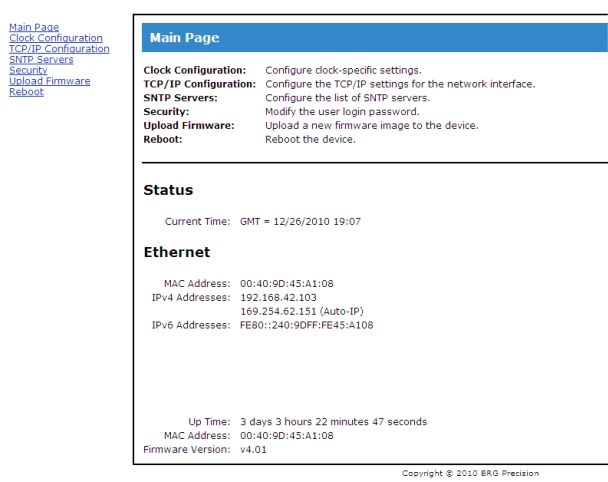
Table of Contents

OPERATION ...................................................................................................................................................................3
MEGA CLOCK PROCESSOR CONFIGURATION MENU .....................................................................................4
ETHERNET COMMUNICATIONS OPTION ..........................................................................................................17
POWER OVER ETHERNET OPTION (POE) ..........................................................................................................23
SERIAL WIRE SYNCHRONIZATION .....................................................................................................................24
PC USB / RS422 ADAPTER.........................................................................................................................................26
PC SERIAL RS232/RS422 ADAPTER .......................................................................................................................27
59TH MINUTE ANALOG MASTER CLOCK OPERATION ...................................................................................29

                                                                                      2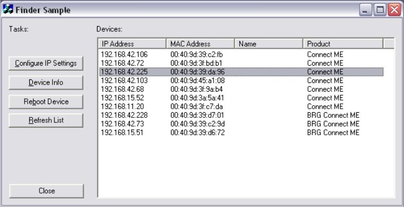
Operation

The BRG Mega clock is based on super bright LED technology coupled with a very capable
microprocessor. The Mega microprocessor is able to store the user’s configuration in duplicate. If
the configuration becomes corrupt by someone configuring the display incorrectly, the original
customer configuration can be instantly restored. The Real Time Clock includes a temperature
compensated quartz crystal as the standard time base and is accurate to a few seconds per year.
For absolute accuracy, several time receiver options are available including, Ethernet employing
Network Time Protocol, BRG Wireless radio receiver, PC serial interface, IRIG-B, and SMPTE
receivers.

Real Time Operation –

The Mega Real Time Clock employs a clock circuit with battery backup. The clock circuit will
maintain time for about ten years without power. When you receive your new clock and apply
power, you will see the clock already running. To correct the time, simply press and hold either the
Up or Down buttons. The time will increment or decrement faster and faster as the buttons are held.

                                                 3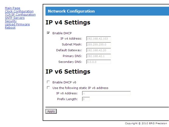
Mega Clock Processor Configuration Menu

Processor Type
Two types of processors are typically used in BRG digital clocks, Tiger and Mega. The Tiger
processor is usually found in timers, counters, and more complex display configurations. The Mega
processor is used where other features are needed that are not available in the Tiger processor, or
displays not requiring features found in the Tiger processor. The Mega processor is available in
general clock as well as special timer configurations. The factory will install the processor type
most appropriate for the customer’s requirements. The menu will indicate the type of processor
used. Once in the menu system, if the Mega processor uses leading zeros and the Tiger processor
does not. If the Mega is configured as specialized timer, then some of the clock functions will not
be available. If Mode 10 does not display a value when access is attempted through the menu, then
the Mega is configured as a specialized timer.

When the Mega is displaying real time, simply press the Up button to advance the time, or the
Down button to decrement the time. The longer the buttons are held down, the faster the time will
change. Press the Mode button to enter modes listed below.

 First Menu        Value                                Mode Description and Instructions
    Level          Range
Mode Number

Menu Selection   Operating     1- Press and hold the Mode button for 3-4 seconds, or until 01 appears on the
                 Value.           display. If the customer’s configuration was previously saved to secondary
                                  memory, all segments on all displays will illuminate while the mode button is
                                  held down.

                               2- Once in the menu system, use the Up and Down buttons to move to the
                                  desired parameter address.

                               3- Once at desired parameter address, press the Mode button once to display
                                  the parameter value.

                               4- Use the Up and Down buttons to change the parameter value.

                               5- Press the Mode button to return to the parameter address or press the
                                  Timer Control button to save any changes and exit the menu system.

                               6- To exit the menu system, press the Timer Control button, or use the Down
                                  button and move to parameter address 00. The clock will return to normal
                                  display mode.

0. Change Time   00:00 to      Simply press the Up button to advance the time, or the Down button to decrement the
                 23:59 or      time. The longer the buttons are held down, the faster the time will change. Press the
                 12:00 AM to   Mode button to enter modes listed below.
                 12:00 PM

                                                       4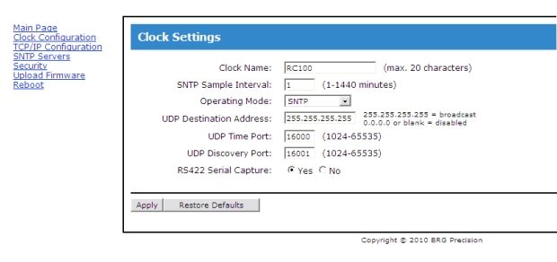
First Menu      Value                              Mode Description and Instructions
      Level        Range
 Mode Number
1.              01 to 31    Day of the Month
                            Pressing the Up button advances the days, pressing the Down button decrements the
                            days. Be sure to use valid day for any specific month. For example, do not enter a
                            day of 30 for the month of February.

2.              01 to 12    Month
                            Pressing the Up button advances the month, pressing the Down button decrements the
                            month.

3.              00 to 50    Year
                            Pressing the Up button advances the year, pressing the Down button decrements the
                            year.

4.              0-4         Blinking Colon
                            To enable the blinking colon, first disable Follow Master Clock by setting Mode 6 to
                            00, then set Mode 4 to 01 to enable the blinking colon. If the clock is connected to a
                            master clock using sync wire, the master clock may be configured to control the
                            blinking colon of all secondary clocks. See also Mode 5 and Mode 41.

                            0=solid colon with no leading zero,
                            1=blinking colon with no leading zero
                            2=no colon with no leading zero
                            3=no colon with leading zero (display modes 2, 5, 17)
                            4=solid colon with leading zero (display modes 2, 5, 17)
                            5=disable blinking sync indicator
                            6=Blink colon if serial sync (Ethernet, PC, Wireless) is lost more than one hour.
                            7=Blink colon if serial sync (Instaset) is received within one hour.

5.                    0,1   12/24 Hour Display Format
                            0=12 hour display format (default), 1=24 hour display format

6.                    0-6   Sync Format
                            Select from various optional sync methods.

                            0= Synchronous three wire circuit (default) –
                            This mode was formerly assigned to value 2 in firmware versions prior to version 4.2.
                            When a voltage is applied to the control line for 8 seconds, the hours will remain
                            unchanged, the minutes will set to 58 and the seconds will set to 02. When a voltage
                            is applied to the control line for 14 seconds, the hours will be set to 5 am or 5 pm
                            (depending on which the current time is closest to), the minutes set to 58 and the
                            seconds set to 08.
                              American: A4015D10
                              ATS: CC2000 Series digital clocks
                              Cincinnati: D10 and D12
                              Dukane: 24SS Series
                              Edwards: 010
                              IBM: 57, 62, 67, 77, 82 and 87 Series

                                                    5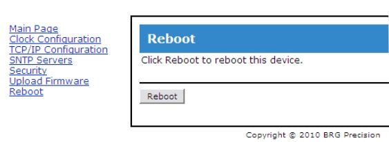
First Menu     Value                              Mode Description and Instructions
    Level       Range
Mode Number
                          Lathem: SS12 Series
                          Simplex: 2310-92xx, 57 and 77 Series
                          Stromberg: 3000

                        0=RS422 – (default) Serial Wire Sync
                        See also Mode 4=6 and Mode 4=7

                        When Mode 17 does not equal zero, down timer commands from a wireless master
                        clock are ignored.

                        0=Ethernet – (default) Ethernet UPD or NTP synchronization
                        See also Mode 4=6 and Mode 4=7

                        900 MHz Digital Radio Control
                        1= receive
                        2= transmit (also set Mode 13=1 to enable transmit mode)
                        3= repeater mode (Mode 13 is set automatically) – not recommended for use with
                        analog clocks. This mode only transmits when a time transmission is received.
                        7= repeater mode only when the hour = 2 (version 6.6 or later) – recommended for
                        use with analog clocks. During repeater period, the clock only transmits if a time
                        transmission is received. All other hours, the clock transmits continuously once per
                        second.
                        See also Mode 12, Mode 13 and Mode 42

                        6=Run timer continuously – (Optional - only available on the Mega Timer)
                        This mode is typically used when display hours or days only. The timer starting value
                        can be changed using the Timer Control button.

7.            -15-15    Display Intensity
                        1=minumum intensity, 15=maximum intensity (default),
                        0=enable auto-brightness (if installed)
                         -1 to -15 alters the effect of auto-brightness (if installed),

8.                      Adjust Time Received for Daylight Saving Time
                        0=disabled
                        1=enabled (default)
                        Removes daylight saving time from serial time data received. By default, the clock
                        expects to receive local serial time updates. If daylight saving time is active, then the
                        time received will be decremented one hour. The hour will be restored when the time
                        is displayed. If daylight saving time is not active, the time will be displayed as it is
                        received, in addition to any time zone offsets.

9.                      Wireless Countdown Timer Configuration
                        0=disabled
                        1 (default) - 9 = clock countdown timer address

                                                  6
First Menu Value Mode Description and Instructions
Level Range
Mode Number
Requires BRG1751v3 or later UHF decoder/receiver
This feature is not available in the default software build.
This mode is used to configure wireless countdown timers. The master clock can
send a command to countdown from 1 to 9 minutes.
Temperature Calibration
0=disabled (default)
10=enabled – This mode is used when calibrating temperature sensors. It will display
the Fahrenheit temperature in tenths of a degree. The display will return to normal
temperature display mode when the power to the clock is cycled.
10. 0,1,2,3, Daylight Savings Time Automatic Switching
(unavailable on the Mega Timers)
This mode has been discontinued beginning with Version 7.4. See Modes 50 and
51 for rule based switching between Daylight and Standard time.
0 = disabled
1 = old U.S. daylight saving time (disabled in ver. 5.9 and later)
2 = UK daylight saving time,
3 = US daylight saving time rule (default),
When this feature is enabled, the time will automatically switch between standard and
daylight saving time.
11. -12 to +13 Time Zone Offset
(unavailable on the Mega Timers)
-12 to 13,
0=default
This feature allows adjusting time received from an external source to the local time.
Mode 53 allows an additional positive offset from 0-60 minutes.
12. 900 MHz Digital Radio Channel Selection
This mode determines the radio channel to be used. (ver. 5.1 or later)
20 = (default) U.S. / Canada - radio channel - scan all channels in receive mode
Channels 16-55 should be used in repeater mode, and optionally for receive and
transmit modes.
16-47 - U.S. / Canada - radio channel - scan all channels in receive mode
48-55 - Australia / New Zealand - radio channel - scan all channels in receive mode
7First Menu Value Mode Description and Instructions
Level Range
Mode Number
Channels 56-95 can be used in receive or transmit modes.
56-87 – U.S. / Canada - no channel scanning– includes +40 offset
88-95 - Australia / New Zealand – no channel scanning– includes +40 offset
Transmit and Repeat mode always uses fixed channel assignments.
900 MHz Repeaters
Beginning with version 6.8, when the clock is configured as a repeater (Mode 6=3), it
will wait to receive a time transmission before transmitting the time. When time data
is received, the clock switches from receive mode to transmit mode, waits 2 seconds,
then sends time packets every second for the next 8 seconds. It then switches back to
receive mode and awaits anther time transmission.
By default, repeaters use both odd and even channels; therefore, it is recommended to
configure Mode 12 to use only even channel numbers in case multiple repeaters are
deployed. The repeater will receive on the channel specified in Mode 12 and transmit
on the next higher channel. For Mega version 5.5 and later, Mode 43 may be used to
configure a repeater transmit channel other than the receive channel plus one. The
default is 1. If Mode 43 is a value other than one, then it is used as the repeater
transmit channel. For example, if Mode 12 = 47 and Mode 43=16, then the repeater
would receive on channel 47 and transmit on channel 16.
Mode 13 is automatically set when configured as a repeater.
Channels 16-55 should be used in repeater mode.
Example 900 MHz system with master clock, repeaters, and slave analog and
digital clocks:
Tiger Master Clock Configuration
Configure master clock to transmit once per second on channel 48
Repeater Number 1
Mode 4=6 – enable blinking colon sync detector
Mode 6=3 – enable repeater mode
Mode 10=0 – disable daylight saving time
Mode 12=48 – repeater receive channel, will transmit on channel 49
Mode 42=1 – group number for Australia
Mode 44=0 – disable cyclic redundancy for time packet reception
Mode 45=100 – (default) reduce propagation delay between repeaters
Repeater Number 2
Mode 4=6 – enable blinking colon sync detector
Mode 6=3 – enable repeater mode
Mode 10=0 – disable daylight saving time
Mode 12=49 – repeater receive channel, will transmit on channel 50
Mode 42=1 – group number for Australia
Mode 44=0 – disable cyclic redundancy for time packet reception
Mode 45=100 – (default) reduce propagation delay between repeaters
8First Menu Value Mode Description and Instructions
Level Range
Mode Number
Repeater Number 3
Mode 4=6 – enable blinking colon sync detector
Mode 6=3 – enable repeater mode
Mode 10=0 – disable daylight saving time
Mode 12=50 – repeater receive channel, will transmit on channel 51
Mode 42=1 – group number for Australia
Mode 44=0 – disable cyclic redundancy for time packet reception
Mode 45=100 – (default) reduce propagation delay between repeaters
All Mega Slave Clocks
Mode 4=6 – enable blinking colon sync detector
Mode 6=1 – enable repeater mode
Mode 10=0 – disable daylight saving time
Mode 12=48 – will scan all channels in receive mode
Mode 42=1 – group number for Australia
Mode 44=0 – disable cyclic redundancy for time packet reception
Mode 45=100 – (default) reduce propagation delay between repeaters
All Analog Slave Clocks
Configure to scan all channels in receive mode
Configure as group 1 for Australia
Setting this mode to a channel less than 56 will cause the radio to scan all available
channels while in receive mode (Mode 6=1).
See also Mode 6, Mode 13, Mode 42, Mode 44 and Mode 45
13. Serial Transmit
0=disabled (default)
1=enabled
See also Mode 6, Mode 12 and Mode 42
14. 1-3 Display Operating Mode
1=real time clock (default),
2=Up timer, short or long duration – (Optional)
3=Down timer, short or long duration – (Optional)
Real Time Adjustment – Press the up or down buttons to change the hours and
minutes. The seconds will set to zero when changing the time. Holding the buttons
down will cause the value to change faster.
Optional Timer Value Adjustment - Momentarily press the Timer Control button.
The first display will be at half brightness, all other displays will blank out. If only
one display is used, it will go to half brightness. Press the up and down buttons to
adjust the value. Holding the buttons down will cause the value to change faster and
faster. Momentarily press the Timer Control button again to move to the next display.
When the last display is adjusted, press the Timer Control button again to return to
9First Menu Value Mode Description and Instructions
Level Range
Mode Number
normal operation. All displays will return to the same brightness. Set Mode 6 = 6 to
run the timer continuously. The Start/Stop/Reset buttons are disabled in the
continuous run mode.
If power is lost, the display will blank out, but the timer will hold the last time. When
power is restored, the last time will be displayed. The timer may need to be adjusted
if the power was out for an extended time.
Optional Timer Button Operation (disabled if Mode 6=6)-
When the timer is stopped –
1. Pressing the Start button will start the timer running.
2. Pressing the Reset button will reset the values to 0.
The right decimal point will light when the timer is stopped.
When the timer is running –
1. Pressing the Start button will pause the timer.
2. Pressing the Stop button will pause the timer.
3. If the timer is configured to continuously run (Mode 6=6), then pressing the
Stop button will reset the time back to the starting value and continue running from
that point.
The right decimal point is off when the timer is running.
When the timer is paused –
1. Pressing the Start button will star the timer.
2. Pressing the Stop button will reset the values to 0.
The right decimal point will light when the timer is paused.
15. Leading Zero on Selected Display Modes
0=disabled,
1=enabled
When enabled, leading zeros will appear on display modes 2, 5, and 17.
16. -999-999 Temperature Adjustment – Channel 1
0=default
This value is used to adjustment the temperature reading up or down in tenths of a
degree Centigrade.
17. -999-999 Temperature Adjustment – Channel 2
0=default
This value is used to adjustment the temperature reading up or down in tenths of a
degree Centigrade.
When Mode 17 does not equal zero, down timer commands from a wireless master
clock are ignored.
10First Menu Value Mode Description and Instructions
Level Range
Mode Number
18. 1-4 Number of Four Digit Displays Installed
1-4,
2=default,
This value determines how many four digit displays are installed. Double and four
sided displays may use a value of 1 to set all four sides to the same display. Other
combinations are possible.
19. N/A Displays the software version number of the clock.
20. 1-99 Sets various display modes for the first display
The following modes are available:
1 - ssxx – seconds left justified
2 - hh:mm – hours and minutes (default)
4 - nnnn – four digit year
5 - mm/dd – month and day
9 - xxxx – blank display
12 - mm:ss – minutes and seconds
13 - xssx – seconds centered
17 - dd/mm – international date format – day/month
20 - hh:mm – hours and decimal minutes
21 - nnnn – timer days (-9999 – 9999) – (Optional)
22 - nnnn – timer hours (-9999 – 9999) – (Optional)
24 - nnoF – degrees Fahrenheit – Channel 1
25 - nnoC – degrees Centigrade – Channel 1
26 - nnoF – degrees Fahrenheit – Channel 2
27 - nnoC – degrees Centigrade – Channel 2
21. 1-99 Sets various display modes for the second display.
See Mode 20 for available display modes. The default display format is 13.
22. 1-99 Sets various display modes for the third display.
See Mode 20 for available display modes. The default display format is 2.
23. 1-99 Sets various display modes for the fourth display.
See Mode 20 for available display modes. The default display format is 2.
28. 0-99 Rotating Display Delay for Cycle Position 1 (Ver. 2.0 or later required)
4 = (default) Up to 3 display formats may be cycled or rotated. This mode setting
determines the time in seconds each display format is displayed. See Modes 31
through 36 to assign the desired display formats. For example, to display hours and
minutes on display 1 and a temperature alternating between degrees F and degrees C
on display 2, using temperature sensor port 1, then set Modes 31=2, 32=2, 34=24 and
35=25.
29. 0-99 Rotating Display Delay for Cycle Position 2 (Ver. 2.0 or later required)
11First Menu Value Mode Description and Instructions
Level Range
Mode Number
4 = (default) Up to 3 display formats may be cycled or rotated. This mode setting
determines the time in seconds each display format is displayed. See Modes 31
through 36 to assign the desired display formats. For example, to display hours and
minutes on display 1 and a temperature alternating between degrees F and degrees C
on display 2, using temperature sensor port 1, then set Modes 31=2, 32=2, 34=24 and
35=25.
30. 0-99 Rotating Display Delay for Cycle Position 3 (Ver. 2.0 or later required)
4 = (default) Up to 3 display formats may be cycled or rotated. This mode setting
determines the time in seconds each display format is displayed. See Modes 31
through 36 to assign the desired display formats. For example, to display hours and
minutes on display 1 and a temperature alternating between degrees F and degrees C
on display 2, using temperature sensor port 1, then set Modes 31=2, 32=2, 34=24 and
35=25.
31. 0-99 Display Format – Display 1, Cycle Position 1
The display format will be displayed on display 1, in display cycle 1. See Mode 30 to
adjust the time delay before switching display formats.
32. 0-99 Display Format – Display 1, Cycle Position 2
The display format will be displayed on display 1, in display cycle 2. See Mode 30 to
adjust the time delay before switching display formats.
33. 0-99 Display Format – Display 1, Cycle Position 3
The display format will be displayed on display 1, in display cycle 3. See Mode 30 to
adjust the time delay before switching display formats.
34. 0-99 Display Format – Display 2, Cycle Position 1
The display format will be displayed on display 2, in display cycle 1. See Mode 30 to
adjust the time delay before switching display formats.
35. 0-99 Display Format – Display 2, Cycle Position 2
The display format will be displayed on display 2, in display cycle 2. See Mode 30 to
adjust the time delay before switching display formats.
36. 0-99 Display Format – Display 2, Cycle Position 3
The display format will be displayed on display 2, in display cycle 3. See Mode 30 to
adjust the time delay before switching display formats.
40. 0,1 Reverse Down Direction Timer at Zero
0=disabled – timer stops at zero
1=enabled (default) – timer reverses at zero
41. 0,1,2 Reverse Decimal Point
0=normal decimal (default),
1=reverse the position of the decimal point for discrete digit displays.
2=add colon to display modes 1 and 2 for discrete displays
3=turn on decimal when sync received, reset at midnight
4=turn on decimal when sync lost, , reset at midnight
5=turn on decimal when sync received, reset hourly
6=turn on decimal when sync lost, reset hourly
7=blank display except for decimal when sync lost
12First Menu Value Mode Description and Instructions
Level Range
Mode Number
42. 0-99 Digital Radio Group Number
0-99 (5=default)
This mode allows changing the digital radio group number. The current group
number will not display. The group number is changed immediately upon exiting this
mode.
See also Mode 6, Mode 12 and Mode 13
43. 1-55 Digital Radio Repeater Channel
1-56 (1=default)
U.S. Channel range = 16-47
Australia Channel range = 48-55
For Mega version 5.5 or later, Mode 43 may be used to configure a repeater transmit
channel other than the receive channel plus one. The default is 1. If Mode 43 is a
value other than one, then it is used as the repeater transmit channel. For example, if
Mode 12 = 47 and Mode 43=16, then the repeater would receive on channel 47 and
transmit on channel 16.
44. 0-2 Serial Time Sync Cyclic Redundancy
This mode has been discontinued beginning with Version 7.4
0 = disabled
1 = compare two time receptions, UHF systems set time twice per hour (default)
2 = compare three time receptions, UHF systems set time once per hour
This mode improves the reliability of time packets received by comparing 2 or 3
packets received. The hour, day, month and year must be equal in all packets
compared before the packet will be used to set the time in the clock.
45 0-250 900 MHz Repeater Propagation Delay Cancellation
100=default
This mode is used to adjust and cancel out the propagation delay caused by using 900
MHz repeaters.
46 0-9999 Sync Source Timeout
5=default
Set the seconds delay before implementing the display action specified in Mode 41
when sync reception is lost.
50 0-9999 Automatic Switching Between Daylight Saving and Standard Time – Start DST
This mode is available in version 7.4 and later.
Default=327 (Start DST the Second Sunday in March)
Rule driven switching between Daylight Saving and Standard time uses a coded
13First Menu Value Mode Description and Instructions
Level Range
Mode Number
value. The format is MMID, where MM = month (1-12), I = instance of the selected
day of the week (1-5, 5=last instance), D = day of the week (1-7), where 1=Monday
and 7=Sunday. For example, 327 represents the second Sunday in March, or 1117
represents the First Sunday in November. If the value >2000 then the right two digits
represent the day of the month. The left two digits, minus 20, equal the month. For
example, March 15th = 2315, April 1st = 2401.
See also Modes 51, 52, and 53
51 0-9999 Automatic Switching Between Daylight Saving and Standard Time – End DST
This mode is available in version 7.4 and later.
Default=1117 (End DST the first Sunday in November)
Rule driven switching between Daylight Saving and Standard time uses a coded
value. The format is MMID, where MM = month (1-12), I = instance of the selected
day of the week (1-5, 5=last instance), D = day of the week (1-7), where 1=Monday
and 7=Sunday. For example, 327 represents the second Sunday in March, or 1117
represents the First Sunday in November. If the value >2000 then the right two digits
represent the day of the month. The left two digits, minus 20, equal the month. For
example, March 15th = 2315, April 1st = 2401.
See also Modes 50, 52, and 53
52 0-12 Hour to Switch Between Daylight Saving and Standard Time
This mode is available in version 7.4 and later.
Default=2
This mode determines the hour of the day to switch between Daylight Saving and
Standard Time.
See also Modes 50, 51, and 53
53 0-60 Forced Time Zone Offset in Minutes
This mode is available in version 7.4 and later.
Default = 0
This Mode Determines the number of minutes that will be added to the stored time
before it is displayed. It can be used to implement special case time zone offsets. For
example, to display time for St. Johns, Newfoundland which uses and offset of UTC
minus 3:30 hours, set Mode 11 = -4 and Mode 53 = 30. A negative 4 hours plus a
positive 30 minutes equals and offset of negative 3 hours and 30 minutes.
See also Mode 11
81 0-3 Ultra-High Precision Oscillator Support
Oven Controlled (OCXO) and Rubidium (RbO) Oscillator Configuration
14First Menu Value Mode Description and Instructions
Level Range
Mode Number
0 (default) disable ultra-precision support,
1=calibrate the TCXO using the OCXO or RbO once per minute,
2=calibrate the TCXO using the OCXO or RbO once per hour,
3=calibrate the TCXO using the OCXO or RbO once per day
Port 65 - OCX Reset Output
Port 66 - OCX 1 BPS input
82 0,1 Enable/Disable Up and Down Buttons
0=enabled
1=disabled (default)
This mode allows disabling the Up and Down buttons to prevent ina changing the time
of a high accuracy (OCXO) synchronized clock.
84 0-199 Automatic Leap Second Adjustment
0=disabled (default)
The mode is used when a leap second will occur sometime in the future and external
synchronization is not used. It is normally used with ultra-high precision oscillators
such as oven controlled or Rubidium oscillators.
A value of greater than 0 and less than 100will add a leap second on June 30 at
23:59:59 UTC of the designated year.
A value greater than 100 will add a leap second on December 31 at 23:59:59 UTC of the
designated year (100+Year).
A value of 99 will add a leap second on the current day at 23:59:59.
During the change, at midnight, 0:00:00 displays for two seconds. When the leap
second is added, Modes 32-84 will be reset to 0.
91. NA
92. NA Restore Factory Defaults
This command restores all factory default parameters and restarts the clock.
93. NA Restore User Defaults
This command restores the user parameter configuration previously stored using
Mode 94. If no parameters were previously stored using Mode 94, then this
command will have no effect.
94. NA Store user Parameters Into Secondary Memory
All configuration parameters are automatically stored into primary memory. This
command stores the current clock configuration into secondary storage. If the
primary clock configuration becomes unusable, the clock can be restored to the
original user configuration using the command. This avoids the necessity to re-enter
the user parameters again.
15First Menu Value Mode Description and Instructions
Level Range
Mode Number
To save the current clock configuration into secondary memory, once Mode 94
appears on the display, press the Mode button once and release. Then press and hold
the Mode button until all display segment illuminate, then release. The clock will
return to normal display Mode once the parameters are restored.
If user parameters have been previously saved to secondary memory, all segments
will illuminate on the menu display when the entering the menu system. All
segments will appear as long as the Mode button is pressed, when first entering the
menu system.
95. NA Illuminate All Display Segments
Pressing the Mode button momentarily will illuminate all display segments on all
displays. Pressing the Mode button again will return to the menu.
96. NA Test Watchdog Timer
The Mega processor includes a hardware watchdog timer. If for any reason the clock
becomes unstable for enters an endless program loop, the watchdog timer will
automatically restart the clock. The watchdog timer operation may be tested by
placing the clock into an endless program loop. Press the Mode button once to test
the clock. Once the Mode button is release, the watchdog timer will reset the clock in
two seconds and will return to normal display mode.
16Ethernet Communications Option
Overview
Once the clock is connected to the network and power is applied, DHCP is used to automatically
assign each clock an IP address on the network. The clock will then search the Internet or local area
network for NTP time servers. NTP (Network Time Protocol) is a uniform method of sending time
over a computer network. By default, the clock will automatically connect to the local network and
attempt to act as a client to public or local SNTP time servers. SNTP is a subset of the NTP
protocol. SNTP provides Universal Coordinated Time (UTC) to the clock. The clock then
implements local time zone offsets and daylight saving rules to display the correct local time. The
correct time will display within a few minutes of obtaining a time server lock. The clock includes a
list of 10 Internet SNTP time servers. Local SNTP time servers may also be used. The clock
includes a network web server which is used to configure various network communication
parameters.
Ethernet Interface
The Ethernet interface includes an easy to use web interface. Automatic address configuration
(DHCP) is enabled by default. However, if a fixed network address will be used instead of DHCP,
then the interface configuration will need to be changed.
To configure the Ethernet interface, it must first be located on the network. The Clock Control
program is used to discover clock(s) located on the same subnet as the PC. Alternatively, a program
is available (finder.exe) that will locate the clock most anywhere on the local network if DHCP
successfully configured it.
The finder.exe program is a software tool that can be used to locate the Ethernet interface just about
anywhere on the local network. However, it cannot be used to configure the interface. Compare
17the MAC address on the product label with those listed on the finder.exe program. If there is a
match, then the IP address will be listed next to it.
Once the IP address is discovered, click on the desired address to configure. Then, click on the
"Browse" button to access the configuration menu where the IP address, net mask, and gateway
address can be entered.
Another method of configuring the Ethernet interface is to connect the PC directly to the Ethernet
interface using a special cross over cable. Later model computers will automatically detect the need
to cross over the signal pairs. All network connections must be disabled on the computer except
"Local Area Connection". Right click on the network icon at the bottom of the screen. Click on
“Open Network Connections”, or go to, Start > Control Panel > Network Connections. If "Local
Area Connection" is not the only enabled connection, right click on the other connections and click
on disable.
Network Interface Configuration Web Interface
The main page displays a variety of general information about the configuration and activity of the
Ethernet interface.
User Name and Password
The menu in the left column allows selecting several sections of the interface. A user name and
password is required to enter any section other than the main page.
18The default user name is: user
The default password is: password
The user name and password should be changed after installation. Store the user name and
password in a safe location for later reference.
Clock Configuration
Clock Name - is the user defined name used to identify the device during a network search.
SNTP Sample Interval - is the time in minutes between SNTP time updates. The default is one
minute.
Operating Mode - defaults to SNTP and should not be changed unless directed by factory technical
support staff.
UDP Destination Address – is the IP address for the clock to send responses to, typically the control
PC.
UDP Time Port – default 16000, for UDP time broadcasting, not usually used for SNTP time
acquisition.
UDP Discovery Port - default 16001, for UDP commands and discovery by the Windows control
program.
RS422 Serial Capture – is used by factory support staff only.
Click on the Apply button to save changes.
19TCP/IP Configuration
Enable DHCP – check to enable automatic IP address configuration using DHCP. Uncheck to use
manual address configuration. The address fields will be grayed out when checked.
IP v4 Address – enter the IP address using version 4 protocol
Subnet Mask – enter the subnet mask
Default Gateway – enter the gateway IP address
Primary DNS – Domain Naming Service address - required if one or more alphabetic named SNTP
servers will be used. Not required if all SNTP server addresses are numeric.
Secondary DNS - Domain Naming Service address - optional
The factory default addressing mode is DHCP. If your network has a DHCP server, simply connect
the clock to your network and the clock will acquire a leased IP address. The lease acquisition can
be almost immediate or may take several minutes. You can use the Clock Control program to
determine the leased IP address by going to Setup/Clock IP Discovery. You may not see your clock
listed in the discovery panel until it has acquired a lease. You cannot access the Ethernet interface
until it’s acquired an IP address. Once the clock has acquired an IP address, you then select the
clock from the discovery listing by clicking on it. Then click the browse button to open a session to
the Ethernet interface.
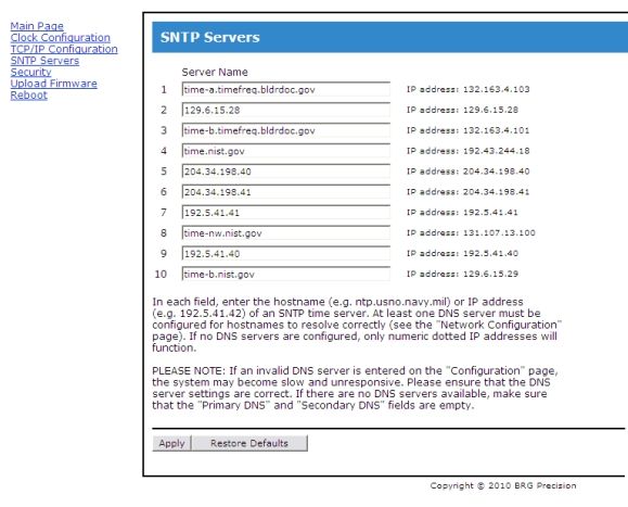
20SNTP Time Servers
Server Name – enter the numeric IP addresses or alphanumeric named addresses of the desired
network time servers. The default configuration includes ten government time server addresses.
Once the clock has an IP address it will attempt to contact the first SNTP time server in the list. If
the network firewall prevents the clock from reaching the Internet, change the SNTP addresses
listed to only local network SNTP time servers. Remove any server addresses outside the local
network.
Security
Change the password as needed. Be sure to store in a safe location for future reference. Click on
the Apply button to invoke the change.
21Reboot
Click on the Reboot button to restart the network interface.
Time Synchronization Problems
If your clock is not synchronizing with an Internet SNTP time server, check the following items:
The NIC must have a valid DHCP or fixed IP address.
The NIC must be in the SNTP operating mode.
If you are using fixed IP addressing, the clock must have the correct gateway address to
access the Internet. The gateway is the first router that the clock must go through to access
other networks or the Internet.
Your network firewall must allow the clock to access the Internet through port 123.
The clock must have the default NTP timer server IP address loaded into the NIC.
If using named SNTP servers, be sure a valid DNS address is provided, or use only numeric
SNTP server addresses.
If your clock is not synchronizing with a local network NTP time server, check the following items:
The NIC must have a valid DHCP or fixed IP address.
The NIC must be in the SNTP operating mode.
If you are using fixed IP addressing, the NIC must have the correct gateway if the server is on
another network. The gateway is the first router that the clock must go through to access other
networks.
The correct NTP timer server IP address must be loaded into the NIC.
If using named SNTP servers, be sure a valid DNS address is provided, or use only numeric
SNTP server addresses.
Technical Support
For BRG Technical Support, call 1-316-788-2000, 8am-5pm, U.S. Central time, or email
www.support@brightclock.com.
22Power over Ethernet Option (PoE)
Power-over-Ethernet (PoE) is a network standard based on IEEE 802.3af that provides a means of delivering power to
devices connected to the LAN. This technology eliminates AC electrical wiring, wall transformers, allows centralized
UPS backup, and is fully compatible with both powered and non-powered Ethernet devices.
In addition to providing time synchronization and control over Ethernet, PoE enabled Ethernet cable provides power to
the clock. System installers need run only a single Ethernet cable that carries both power and data to each clock. This
allows greater flexibility placing clocks and, in most cases, significantly decreases installation costs. BRG clocks are
fully compliant with the IEEE 802.3af standard for providing power over Ethernet. The clocks will work with older
non-standard and passive power sources, as well as newer, auto-sensing PoE switches and mid-span power injectors.
Power-over-Ethernet begins with a Ethernet power source such as a PoE compatible Switch or a mid-span power
"Injector". These devices insert power onto the Ethernet cable. The power source is typically installed in the "wiring
closet" near the Ethernet switch or hub.
Clocks may be ordered as PoE compatible by adding the (P13) power option. This option adds the necessary circuitry to
fully implement the IEEE 802.3af standard. PoE is able to supply a maximum of about 15 watts of power over the
Ethernet cable. This means that not all clocks are candidates for PoE.
If the access point is not PoE compatible, BRG offers single port mid-span power injectors designed to provide power
to a single clock (P14 power option). Multiport mid-span PoE power injectors are available from most network
equipment vendors. The voltage injected is 48 volts DC at 0.35 Amps.
Power Over Ethernet (PoE)
Customer supplied Ethernet switch BRG Digital Clock
with internal 48 volt PoE supply with PoE option
Sw itch
Ethernet Cable
(up to 100m or 325ft)
Customer supplied Ethernet switch
with mid-span 48 volt PoE supply
Switch
BRG Digital Clock
with PoE option
Pow er Injector Ethernet Cable
(up to 100m or 325ft)
Customer supplied Ethernet switch BRG Digital Clock
with single external PoE supply with PoE option
Ethernet Cable
Switch
(up to 100m or 325ft)
BRG Suppl ied
Ethernet
Pow er Injector
BRG Supplied
AC Power Adapter
23Serial Wire Synchronization
The RS-422 protocol used for wire sync communications greatly expands the practical possibilities of the serial bus. It
provides a mechanism by which serial data can be transmitted over great distances (to 4,000 feet). This is accomplished
by splitting each signal across two separate wires in opposite states, one inverted and one not inverted. The difference in
voltage between the two lines is compared by the receiver to determine the logical state of the signal. This wire
configuration, called differential data transmission, or balanced transmission is well suited to noisy environments. With
balanced transmission, this potential difference will affect both wires equally, and thus not affect their inverse
relationship. Twisted pairs of wire, which ensure that neither line is permanently closer to a noise source than the other,
are often used to best equalize influences on the two lines. Errors can also be caused by high noise levels which affect
one side of the receiver to a different extent than the other. To combat this, each receiver is generally grounded.
RS422 Serial Communications
BRG clocks utilized an industry standard RS422 buss transceiver that meets or exceeds ANSI Standards EIA/TIA-422-
B and ITU Recommendation V.11. This device includes the following features for improved reliability: USE ONLY
RS422 VOLTAGES. DO NOT APPLY POWER VOLTAGES TO THE SYNC WIRING.
1. Thermal Shutdown Protection
2. Positive and Negative Current Limiting
3. 60 mA Output Current
4. Automatic Noise Suppression
One BRG clock will drive up to 5 slave clocks when wired in parallel, or an unlimited number of
clocks if they include and input, and output and are wired in series.
Common Cat-5 twisted pair data cable may be used to carry serial data between clocks. DO NOT USE POWER WIRE
OR NON-TWISTED WIRE AS DATA CABLE.
Use only 1 twisted pair
Use only 1 twisted pair
Cat-5 Data Cable
Unused twisted pairs Unused twisted pairs
Diagnostics –
With power applied to the clock, connect a red ohm meter lead to the red Input sync wire and the black ohm meter lead
to the black Input sync wire. You should see a reading of 120 ohms. A lower resistance indicates a short in the sync
wiring or clock circuit. A higher resistance indicates a disconnected sync wire or a problem with the clock’s sync
circuit.
The sync output of the clock may be measured with a volt meter. There should be 5 volts when the meter’s read lead is
connected to the red Output sync wire, and the meter’s black lead connected to the clock’s black Output sync wire. If
the clock is configured as a master to send sync data once per second, you will see a momentary voltage drop using an
analog meter. Digital meters may not be fast enough to detect the sync pulse. If the clock is configured as a repeating
slave, it will only send sync data when sync data is received. In other words, it is configured to repeat all sync data
received.
24LED sync detector –
A common LED (light emitting diode) may be used to detect the presence and polarity of sync data. Connect the anode
of the LED to the red Output sync wire and the LED cathode to the black Output sync wire. On most 5mm LED’s, the
anode lead is the longer of the two leads. The LED should continuously illuminate. If the clock is configured to
transmit, the LED should blink off momentarily when the sync data is sent. If the LED polarity is reversed, the LED
will remain off. When the clock sends sync data, the LED will blink momentarily.
Wired Synchronization Examples
The following example illustrates how all clocks may be synchronized to the master using only two wires. The slave clocks repeat the sync signal. Use Cat-5 twisted pair wire for up
to 4,000 feet between any two clocks.
GPS o r
C DMA
Re c ei ve r
Master Slave Slave
Sync Ou t Red Sync In Sync Ou t Red Sync In Sync Ou t Red
More
Black Black
B lack
Clocks
Master Clock includes: Sla ve Clock includes: Sla ve Clock includes:
GPS or CDMA Time Receiver Serial Sync Repeater Serial Sync Repeater
Serial Sync Transmitter
The following example illustrates how the sync wiring may be "T" or "Y" connected to supply more clocks. Any Sync Output may be split to supply two other clocks. This allows
greater flexibility during installation.
GPS o r
C DMA
Re c ei ve r
Master Slave Slave
Sync Ou t Red Sync In Sync Ou t Red Sync In Sync Ou t Red
More
Black Black B lack
Clocks
Master Clock inclu des: Slave Clock includes: Slave Clock includes:
GPS or CDMA Time Receiver Serial Sync Repeater Serial Sync Repeater
Serial Sync Transmitter
Sync In
Slave
Sync Ou t
Slave Slave Slave
Sync In Red Sync In Sync Ou t Red Sync In Sync Ou t Red
B lack Black Black
More
Clocks
Slave Clock includes: Sla ve Clock includes: Sla ve Clock includes:
Serial Sync Repeater Serial Sync Repeater Serial Sync Repeater
25PC USB / RS422 Adapter
USB/422 Adapter
This option allows the clock to be set by PC or the PC to be set by the clock. A USB interface adapter is
included for connecting the clock to a computer. Simply attach the adapter to the clock sync line and plug
into the PC's USB port. A software CD is included for the Windows operating system. A driver is also
included on the BRG Digital Clock controller software CD under the directory – USB Adapter Driver 2.0.
The driver can also be downloaded from http://www.brgprecision.com. Windows will detect the USB
connection and will direct you to insert the CD. Once connected, the time and date may be exchanged
between the PC and clock(s). The scheduling program included with Windows can be configured to run the
time send software anytime between once per minute and once a day, or longer. The serial sync options, ST
and/or SR, are required. This will strip off daylight savings time and convert the local time to UTC time for
use by the time zone display. One BRG clock will drive up to 5 slave clocks when wired in parallel,
or an unlimited number of clocks if they include and input and output and are wired in series.
PC/Clock USB Interface Adapter package includes: USB Adapter, USB patch cable, software CD,
installation and operating instructions (this sheet). The USB adapter draws its’ power directly from the
USB port. No AC power module is required.
PC / Clock USB Port Adapter
Example 1- Send time/date from PC to CLOCK(S)
To PC's
USB Data to Clock
Li nk TX
Port RX+
RX -
TX+ RED
TX - BLACK
RX
SYNC RECEIVE (SR)
Clock/PC USB Port Adapter
SYNC TRANSMIT (ST)
SYNC WIRE TO
MORE CLOCKS
Example 2 - Send time/date from CLOCK to PC
To PC's
USB
Data from Clock
Li nk TX
Port RX+ RED
RX - BLACK
TX+ SYNC TRANSMIT (ST)
TX -
RX
SYNC WIRE TO
Clock/PC USB Port Adapter MORE CLOCKS
26PC Serial RS232/RS422 Adapter
Ic485-I Adapter
This option allows the clock to be set by PC or the PC to be set by the clock. A serial interface
adapter is included for connecting the clock to a computer. Simply attach the adapter to the clock
sync line and plug into the PC's serial port. Software is included for DOS, Windows 3.x, 95, 98,
NT, ME, XP and 2000. Once connected, the time and date may be exchanged between the PC and
clock(s). The scheduling program included with Windows can be configured to run the time send
software anytime between once per minute and once a day, or longer.
RS422 Serial Communications
BRG clocks utilized an industry standard RS422 buss transceiver that meets or exceeds ANSI
Standards EIA/TIA-422-B and ITU Recommendation V.11. This device includes the following
features for improved reliability:
1. Thermal Shutdown Protection
2. Positive and Negative Current Limiting
3. 60 mA Output Current
4. Automatic Noise Suppression
One BRG clock will drive up to 5 slave clocks when wired in parallel, or an unlimited number of
clocks if they include and input and output and are wired in series.
Diagnostics –
With power applied to the clock, connect a meters red lead the red Input sync wire and the black
meter lead to the black Input sync wire. You should see a reading of 12 K ohms. A lower
resistance indicates a short in the sync wiring or clock circuit. A higher resistance indicates a
disconnected sync wire or a problem with the clock’s sync circuit.
The sync output of the clock may be measured with a volt meter. There should be 5 volts when the
meter’s read lead is connected to the red Output sync wire, and the meter’s black lead connected to
the clock’s black Output sync wire. If the clock is configured as a master to send sync data once per
second, you will see a momentary voltage drop using an analog meter. Digital meters may not be
fast enough to detect the sync pulse.
If the clock is configured as a repeating slave, it will only send sync data when sync data is
received. In other words, it is configured to repeat all sync data received.
27LED sync detector -
A common LED (light emitting diode) may be used to detect the presence and polarity of sync data.
Connect the anode of the LED to the red Output sync wire and the LED cathode to the black Output
sync wire. On most 5mm LED’s, the anode lead is the longer of the two leads. The LED should
continuously illuminate. If the clock is configured to transmit, the LED should blink off
momentarily when the sync data is sent.
If the LED polarity is reversed, the LED will remain off. When the clock sends sync data, the LED
will blink momentarily.
PC/Clock Serial Interface Adapter package includes: Serial Adapter, 9 to 25 pin adapter, software
CD, installation and operating instructions (this sheet). The serial adapter draws its’ power
directly from the serial port. No AC power module is required.
Example 1- Send time/date from PC to CLOCK(S)
Data to Clock
RS-232 RED
to PC SYNC RECEIVE (SR)
BLACK
Serial
Port
SYNC TRANSMIT (ST)
Clock/PC Serial Port Adapter
SYNC WIRE TO
MORE CLOCKS
Example 2 - Send time/date from CLOCK to PC
RS-232
to PC Data from Clock
Serial RED
SYNC TRANSMIT (ST)
Port BLACK
Clock/PC Serial Port Adapter
SYNC WIRE TO
MORE CLOCKS
2859th Minute Analog Master Clock Operation
Description
A single BRG digital clock may control 500 or more 59th minute analog slave clocks. 59th minute
analog clocks are used for their increased reliability over older analog clock systems. The 59th
minute analog clock contains a microprocessor that greatly reduces the power required compared to
older clock designs. No relays, ratchets or pawls are used. All power and sync pulses to the analog
clocks are provided over a simple three-wire circuit. The master clock sends minute and second
correction impulses hourly. Additionally, at 5am and 5pm, the hour is corrected. In the event of a
power outage, the master clock will continue to keep time up to ten years. When the power returns,
the master clock will correct the analog clocks at the next regular sync interval. If continuous time
display is required during a power outage, a simple off-the-shelf uninterruptible power supply
(UPS) will provide many hours, if not days of operation for the entire system.
Installation
It is recommended to use 14 ga. to 16 ga. wire between the master clock and analog clocks. Any
wiring layout may be used including star, “T”, and buss configurations. More wiring “legs” will
reduce overall wiring resistance. All wiring should be in parallel. If the master clock needs to be
removed for any reason, the slave clocks will continue to operate normally, although they will no
longer receive correction pulses from the master clock.
If a single clock needs to be removed for any reason, unplug the connector plug from the analog
clock’s pins. The master clock may remain powered. To return an analog clock to operation, plug
the connector back onto the analog clock’s pins. The clock will be corrected at the next regular
sync interval.
29You can also read