GIR-3000 Instruction Manual
←
→
Page content transcription
If your browser does not render page correctly, please read the page content below
GIR-3000
                         Headquarters / Engineering research laboratory :
23 Gunpo Advance d Industry 1-ro(Bugok-dong), Gunpo-si, Gyeonggi-do
                                                                            Instruction Manual
                          Tel +82-31-490-0800 Fax +82-31-490-0801

                                    Yeongnam business office / Plant :
     55 Gonghangap-gil 85beon-gil, Gangseogu, Busan Metropolitan City
                              Tel +51-973-8518 Fax +51-973-8519

                                              E-mail : info@gastron.com

                                               www.gastron.com

                                                                                Read in detail for correct use.
GIR-3000
Instruction Manual
                                                                                                                                        Greetings              www.gastron.com
                                                                                                                                                                         02_03

Gas & Flame                                              We sincerely thank you for purchasing the product of Gastron Co. Ltd.
                                                         Our Gastron Co.Ltd. is a company specialized in Gas detector and Gas Monitoring System, being

Detection System
                                                         recognized by many consumers due to the best quality and use convenience. We always enable you
                                                         consumers to find desired products nearby and are ceaselessly studying and striving for development
                                                         of Gas detectors satisfying customers. From now on, solve all anguishes concerning Gas detector with
                                                         the products of Gastron Co. Ltd, We Gastron Co. will take a responsibility and give you satisfaction.

                                                         In the present instruction manual, operation method for Gas detector as well as simple methods for
                                                         maintenance and repair, etc. are recorded If you read it in detail and keep it well, for reference when
                                                         you have questions, then it will give you much help.

                                                           ■ For accurate operation of Gas detector, check up and calibrate for more than once in every 6 months.
                                                             ( * See No. 13 of KOSHA GUIDE : P-135-2013 / 8.3 paragraph on qualification and calibration)
                                                           ■ For accurate operation of Gas detector, checkup and calibration with calibration gas before measurement
                                                             is recommended.
                                                           ■ When not calibrated, it may cause malfunction of the equipment due to problems resulting from Sensor aging.
                                                           ■ When the present instrument should be dismantled, those with professional skills for Gas detector should
                                                             conduct the operation.
                                                           ■ For power supply cable, wire specifications should be determined by referring to the item of "Length of
                                                             installed cable".
                                                           ■ For the contents on checkup and calibration of Gas detector, please use our company's engineering
                                                             department , e-mail, or web site.

                                                         The present product and the product manual can be changed without advance notice for performance improvement and
When abnormalities occur after purchasing the product,   use convenience of the product.
please contact the following address.

·Address : 23 Gunpo Advanced Industry 1-ro,
		 Gunpo-si, Gyeonggi-do
·Tel       : 031-490-0800
·Fax       : 031-490-0801                                * KOSHA GUIDE : P-135-2013
·URL       : www.gastron.com                              Calibration should be executed at the periods required by the manufacturer, and should be executed
·e-mail    : info@gastron.com                             every quarter unless there are separate calibration periods.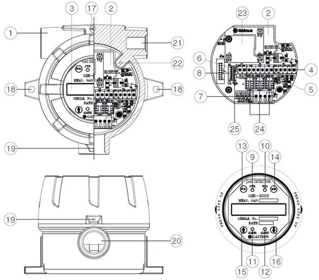
GIR-3000
Instruction Manual
                                                                                              Contents                                                                                           Contents            www.gastron.com
                                                                                                                                                                                                                               04_05

1.   Overview··························································································· 6         6.3.   Operation Flow· ············································································· 22
                                                                                                                   6.4.   Menu Configuration Table· ·································································· 23
2. Structure··························································································· 6
                                                                                                                7. System Mode······················································································· 25
3. Specification························································································ 7
                                                                                                                   7.1.   PROGRAM MODE·············································································· 25
     3.1.   Basic Specifications········································································· 7        7.2.   CALIBRATION MODE··········································································· 26
     3.2.   Mechanical Specifications··································································· 7      		        7.2.1. Zero Calibration······································································ 26
     3.3.   Electrical Specifications (Standard Type)···················································· 8     		        7.2.2. Span Calibration····································································· 27
     3.4.   Environmental Specifications································································ 8         7.3.   ALARM MODE················································································· 28

4. Name and description of each part································································· 9
                                                                                                                8. Troubleshooting···················································································· 30
     4.1.   Components················································································· 9
                                                                                                                   8.1.   Fault List····················································································· 30
     4.2.   Components of infrared sensor······························································ 11
                                                                                                                   8.2.   Recovery List················································································ 31

5. Installation·························································································· 12
                                                                                                                9. Interface configuration·············································································· 32
     5.1.   Separation of Housing Cover······························································· 12
                                                                                                                   9.1.   MODBUS RS485··············································································· 32
     5.2.   Configuration of Main PCB··································································· 12
                                                                                                                		        9.1.1. Interface setting····································································· 32
     5.3.   Configuration of power supply and 4-20mA terminal········································ 14
                                                                                                                		        9.1.2. MODBUS RS485 Register map·························································· 32
		          5.3.1. Wire connection diagram of driving method for 4~20mA Source···················· 14
		          5.3.2. Wire connection diagram of driving method for 4~20mA Sink······················· 14
                                                                                                                10. Outline drawing and Dimensions···································································· 33
		          5.3.3. Wire connection diagram of driving method for 4~20mA 3Wire Sink················· 16
     5.4.   Configuration of Relay terminal and communication terminal· ······························· 16         10.1. Standard Type· ··············································································· 33
		          5.4.1. Configuration of terminal····························································· 16       10.2. Upon coupling of warning light· ····························································· 34
		          5.4.2. Setting for Relay mode······························································· 17        10.3. Upon coupling of Raincover································································· 35
		          5.4.3. Setting for RS485 MODBUS·························································· 17           10.4. GIR-3000 Remote Type······································································ 36
     5.5.   Configuration of sensor connecting terminal ················································ 18
     5.6.   Configuration of Remote Type connection· ················································· 19       11. Notes before installation············································································ 37
     5.7.   Length of installed cable····································································· 20      11.1. Selection of installation place(Data from occupational safety and health regulations)········ 37
                                                                                                                   11.2. Selection of installation place (Data from safety management regulations for high-pressure gas)· ····· 37
6. Operation Flow for sensor········································································· 21
                                                                                                                   11.3. Notes upon installation······································································ 38
     6.1.   Initial operation state (Power On)···························································· 21
     6.2.   Gas measuring state (Measuring Mode)······················································ 21       12. Revision record····················································································· 39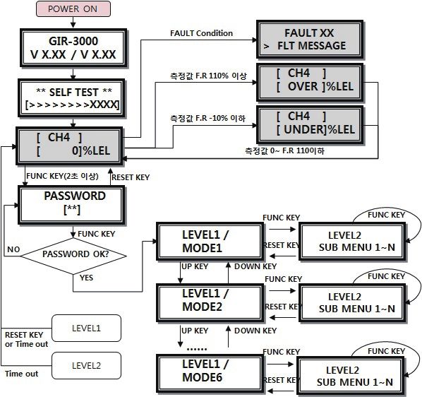
GIR-3000
Instruction Manual
1. Overview 3. Specifications www.gastron.com
06_07
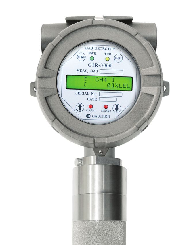
The GIR-3000 infrared Gas detector has been developed to prevent accidents beforehand by detecting various 3.1. Basic Specifications
leaked gases generated in industry fields such as plants producing or using combustible gas, carbon monoxide,
ITEMS SPECIFICATION
carbon dioxide, gas storage place, manufacturing processes, etc.
Measuring Type Diffusion type
The GIR-3000 infrared Gas detector is installed in areas with a risk of gas leakage to display measured values Measuring Value Display Local Digital LCD or OLED Display
with LCD, OLED installed in the detector by continuous detection of gas leakage, providing DC 4~20mA standard Measuring Method Non-Dispersive Infrared(NDIR)
output, Isolation RS-485 communication signal, HART communication, and Relay contact signal of gas Alarm. Also, Combustible Gas
Detectible Gas Carbon dioxide (CO2)
DC 4~20mA standard output can connect up to the maximum of 500m (upon using CVVS or CVVSB 1.5sq↑ Shield
Carbon monoxide(CO)
Cable) in transmission distance of output signals of Gas detector and receiving unit while RS-485 communication Measuring Range 0~9,999ppm / 0~100% LEL /
signal can be transmitted up to1,000m (upon using RS-485 exclusive line). Combustible:
0~100% VOL
CO₂: 1.0% ~ 100% VOL
2. Structure CO: 5% ~ 100% VOL
Accuracy ≤ ±3% / Full Range
Zero Drift ≤2% / Full Range
The GIR-3000’s body is made of aluminum alloy material in a structure of complete pressure-resistant explosion- Response Time 90% of full scale in less than 10 sec
proof type(Ex d IIC T6), can be installed in the areas with a risk of leakage and explosion of all combustible gases, KCs: Ex d llC T6,T4, IP65
displaying leakage situation of gas at the installed field by embedding LCD, OLED in the Gas detector. Inside structure Approvals Classification ATEX/IECEX: II 2 G Ex d IIC Gb T4,T6
SIL2, MED, ABS, DNV
is comprised of liquid crystal unit displaying measured values, connector unit outputting measured values (DC
Basic Interface Analog 4-20mA current interface
4~20mA) or Isolation RS-485 communication (Option) Signal, HART HART Interface HART REV7(Option)
communication signal, and Alarm Signal to outside, and 2 PCB Boards. Outside structure is comprised of Sensor HART Board
unit for detection of gas leakage and Cable lead-in unit (2ea). Calibration operation can be conducted outside of Gas MODBUS RS485 Board
Option
GTL-100 warning light
detector body by using Magnet-bar, making maintenance and repair operation convenient.
Rain Cover
Body (Transmitter) 2Year
Hazardous Area (Filed) Safe Area Warranty
Sensor 1Year
GIR-3000 Gas Detector
Transmitter enclosure 3.2. Mechanical Specifications
ITEMS SPECIFICATION
Display Board Explosion Proof type Pressure-resistant, explosion-proof enclosure
(User Interface)
Dimension 156(W) × 322(H) × 110(D) mm
Weight including Sensor App. 3kg
Mounting type Wall mount
+24V DC Safety Power Supply Unit Mounting Holes Ø 7 ±0.1
Infrared Gas (24VDC)
Main Board
Sensor Module Cable inlet 3/4" PF ( 1/2"or 3/4" NPT )
(Transmitter)
(GSA920) Safety Controller Body (Transmitter) aluminum alloy
4-20mA Analog (PLC or DCS) Body material
Signal Output Sensor Stainless Steel (STS316)
[Figure 1. GIR-3000 Overview]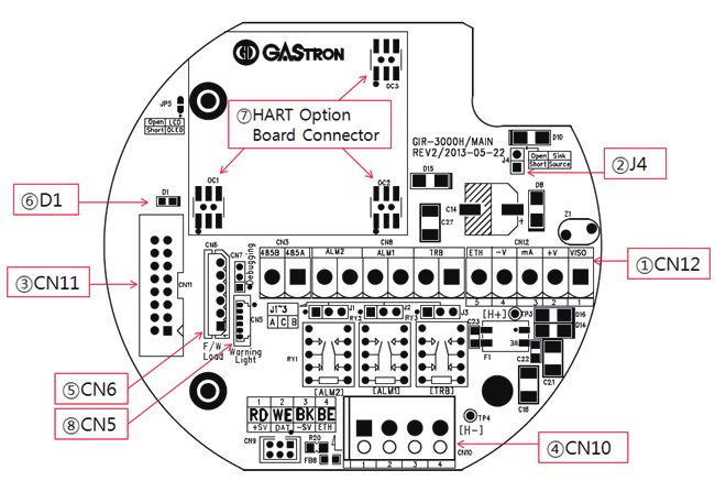
GIR-3000
Instruction Manual
3. Specifications 4. Name and description of each part www.gastron.com
08_09
3.3. Electrical Specifications (Standard Type) 4.1. Components of transmitter
ITEMS SPECIFICATION
Input Voltage(Standard) Absolute min: 18V
※ Customer supplied PSU must meet Nominal: 24V
requirements IEC1010-1 and CE Absolute max: 31V
Marking requirements. Ripple maximum allowed: 1V pk-pk
Max. wattage: 9.6W @+24 VDC
Wattage
Max. current: 400mA @+24 VDC
0-20mA(500 ohms max load)
All readings ± 0.2mA
Measured-value signal:
4mA(Zero) to 20mA(Full Scale)
Analog output Current Fault: 0mA
0-100% LEL: 4mA - 20mA
100-109%LEL: 21.6mA
Over 110% LEL: 22mA
Maintenance: 3mA
Analog output current ripple & noise max ±20uA
Alarm1, Alarm2, Fault Relay
Relay contact
Rated 1.0 A @ 30VDC or 0.5 A @ 125 VAC
Power CVVS or CVVSB with shield
Wiring requirement Analog CVVS or CVVSB with shield
RS485 STP(Shielded Twisted Pair)
[Figure 2. Components of GIR-3000]
Signal transmission distance Analog 2500m
(Cable Connection Length) RS485 1000m
EMC Protection: Complies with EN50270 No ITEMS SPECIFICATION
Protect PCB Board embedded inside Sensor and Housing from change of
1 Housing
outside environments and impact.
3.4. Environmental Specifications Amplify output signals produced by Sensor, and convert to standard output of DC 4~20mA for
2 Main PCB transmission, and output Isolation RS- 485 communication Signal and Alarm relay contact signal.
ITEMS SPECIFICATION Also, send Data to be displayed in Display unit.
Transmitter -40 to 80 ℃ Display Data received from MAIN PCB in LCD or OLED, and
Operation Temperature 3 Display PCB
Sensor -40 to 80 ℃ display the current Event situations by Power lamp, Alarm lamp, Trouble lamp
Transmitter -40 to 80 ℃ Power/Signal CN12 is comprised of power supply of DC18-31V and DC 4~20mA standard output Connection
Storage Temperature 4
Sensor -40 to 80 ℃ Terminal terminal (VISO, +V, mA, -V, ETH).
Alarm signal CN8 is Alarm signal connection terminal, as a terminal where Trouble, Alarm1, Alarm2 Relay
Transmitter 5 to 99% RH (Non-condensing) 5
Operation Humidity Terminal contact are outputted.
Sensor 5 to 99% RH (Non-condensing)
6 RS-485 signal CN3 is Isolation RS-485 communication signal connection terminal(A, B).
Pressure Range 90 to 110KPa
7 Sensor terminal CN10 is Sensor connection terminal. (RD, WH, BK, BE)
Max. air velocity 6m/s
Program Downloading
8 Connector that allows downloading of product program.
Connector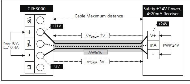
GIR-3000
Instruction Manual
                                                           4. Name and description of each part                                                                      4. Name and description of each part                                      www.gastron.com
                                                                                                                                                                                                                                                         10_11

4.1. Components of transmitter                                                                                                 4.2. Components of infrared sensor

No            ITEMS                                                      SPECIFICATION
 9         Power lamp            Lamp is lighted when .power switch is turned On
10         Trouble lamp          Lighted when abnormality occurs in circuit or sensor sensitivity, etc.
11         Alarm1 lamp           Lighted when gas is leaked to become higher than Alarm1 level
12         Alarm2 lamp           Lighted when gas is leaked to become higher than Alarm2 level
                                 When contact is made for more than 2sec by using Magnet-bar upon parameter setting, it is
13         Function key          converted to Program mode. (Program mode, Calibration mode, Test mode, etc.) Also, it is
                                 used when Data is inputted for setting.
                                 Converted when cancelled during parameter setting or touched for more than once by using
14          Reset key            Magnet bar to return to the previous state. (Converted to the previous mode by one stage at
                                 a time upon every touch.
                                 Converted or transformed by one stage at a time when touched once by using Magnet-bar
15          ↑(Up) key
                                 upon mode conversion or figure transformation (transformed to the higher stage)
                                 Converted or transformed by one stage at a time when touched once by using Magnet-bar
16         ↓(Down) key
                                 upon mode conversion or figure transformation(transformed to the lower stage)
                                 - Outside grounding for protection from outside noise or strong electric field
17        External earth
                                 - For grounding cable, use conductor larger than 4mm upon coupling connection
18          Mount hole           Hole to mount Gas Detector onto outer wall and other installation place.
                                 Fix with a hexagonal lens bolt to prevent drop-off due to outside impacts after assembly of
19     Cover fixed screw(M4)
                                 Detector Housing Body and Detector Housing Cover
20        Sensor thread          Mounting port for mounting of infrared gas sensor (Detector)
                                 Basically PF 3/4" is provided for power supply to Gas detector and lead-in of measurement
21          Cable inlet
                                 output signals upon installation operation.
                                 - Inside grounding of Detector for protection from outside nose or strong electric field
22         Internal earth
                                 - For grounding cable, use conductor larger than 4mm upon coupling connection.
                                                                                                                               No             ITEMS                                                     SPECIFICATION
                                 Connector to connect Isolation Type RS-485 communication Module for communication with
         RS-485 Module /         PC or PLC and HART communication Module. For RS-485 communication, communication               1     Power & Signal cable    Comprised of power supply input, 4-20mA analog signal, and transmitter communication cable.
23                                                                                                                              2     Detector fixed screw    Screw processing part for mounting of transmitter
          HART Module            Address should be set, and the basic value is set for No.1. For HART communication,
                                 Polling-Address and Tag No. etc. should be set. (Optional specifications)                      3         Earth Ground        Outside grounding for protection from outside noise or strong electric field
                                 Configured so as to allow selection of A, B contact. If not in ENERGIZER MODE, it operates     4           Housing           Protect PCB Board embedded inside from change in outside environment or impact
                                 as contact A (Normal Open) when Jumper is connected to the part displayed as silk A, while
          Relay Contact                                                                                                         5           IR Sensor         Sensor device for transformation of IR wavelength to electric signals
24                               it operates as contact B (Normal Close) when Jumper is connected to the part displayed as
          Type Selection                                                                                                        6         IR Tube Lock        Screw for fixing of IR tube
                                 silk B. On the contrary, if in ENERGIZER MODE, it operates as contact B when Jumper is
                                 connected to A, while it operates as contact A when Jumper is connected to B.                  7            IR Tube          Optical path passing infrared wavelength generated in IR lamp
          Warning Light                                                                                                         8             Filter          Filter device for protection of inside optical paths from outside contaminants
25                               Connecting connector when the warning light is used(Optional)
           Connector
                                                                                                                                9           IR Source         Lamp for generation of infrared signals
                               [Table 1. Description on components of GIR-3000 transmitter]                                    10        Calibration port     Inlet for calibration gas upon gas calibration
                                                                                                                               11       Filter fixing screw   Screw for fixing of filter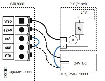
GIR-3000
Instruction Manual
                                                                                                  5. Installation                                                                                         5. Installation            www.gastron.com
                                                                                                                                                                                                                                               12_13

Absolutely no one other the approved users or those of the headquarters in charge of installation and repair should   5.2. Configuration of Main PCB
be allowed to install in the field, open or operate Cover of the installed gas leakage detector. Otherwise serious
                                                                                                                      ■ When Display Parts are separated, the layout diagram for Main PCB terminal as follows can be seen.
damages to life and property may be inflicted. Also, make sure to shut off the power supply and conduct operation
after checking whether explosive GAS remains or flammable substances are present in the surroundings.

5.1. Separation of Housing Cover
■
■ Cover can be separated when the cover for gas
  leakage detector is turned counterclockwise after
  slotted set
■ screw for fixing of body's cover (M4 x 1ea) is turned
  3~4 turns clockwise by using a hexagonal wrench (M2).         Slotted set
                                                                screw (M4)
  When Cover is separated, LCD unit is displayed.

                                  Figure when infrared
                              Sensor(Detector) is mounted
                                                                                                                                                            [Figure 5.Layout diagram for Main PCB terminals]

                                                                              [Figure 3. Slotted set screw]           No               NAME                                                      DESCRIPTION
                                                                                                                       1               CN12              Power & Output Signal Terminal

■ When Cover is separated, separate Display Parts in the                                                               2                 J4              4~20mA Source / Sink selection jumper (ON: Source Type, OFF: Sink Type)
                                                                                                                       3               CN11              Display LCD Connector
  following order.
                                                                                                                       4               CN10              Sensor Connector
  ① Simultaneously push inward the fixing chains on
                                                                                                                       5                CN6              Program download Connector
		    left side and right side on the front face of LCD unit.
                                                                                                                       6                 D1              Status LED (Blinks by the unit of 11 sec in the case of normal operation)
  ② Separate from Gas detector body by pulling Display                                                                 7          OC1, OC2, OC3          HART Option Board Connector
		    Parts forward in the pushed state.                                                                               8                CN5              Warning light (GTL-100) Interface Connector
  ③ Main PCB is installed below Detector Body after
                                                                                                                                                            [Table 3.Description on major parts of Main PCB]
		    separation of Display Parts .

                                                                                                                      ■ By using OC1, OC2, OC3 of the above layout diagram, HART Option or RS485 MODBUS board can be mounted,
                                                                  [Figure 4. Separation method for Display Part]
                                                                                                                           and is fixed by using 3 Ø Screw hoe on the to[ left side of Option board.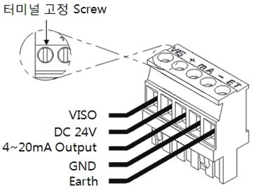
GIR-3000
Instruction Manual
                                                                                                5. Installation                                                                   5. Installation                www.gastron.com
                                                                                                                                                                                                                           14_15

5.3. Configuration of power supply and 4-20mA terminal                                                                5.3.1. Wire connection diagram of driving method
                                                                                                                      for 4~20mA Source
■
■ When Display Parts are separated, Terminal Block in Main PCB can be seen as show in the following figure,           ■ Connect 4-20mA Signal terminal on PLC side to
     which is separated from Main PCB when held by hand and pulled up.                                                  GIR-3000의 'mA', while GND terminal is used in
■ Loosen by turning counterclockwise the terminal-fixing screws at 5 places in the upper part of the separated          common with the power supply. And then turn
     Terminal Block CN12 (VISO, +V, mA, -V, ETH) Connector by using Θ driver, connect DC18-31V power supply             the J1 Jumper ON.
     to +, - , and Signal Cable to mA , followed by locking terminal-fixing screws at 5 places clockwise to prevent   ■ HART Communicator can be used only in the model
     terminal from breaking away, and fit it in Main PCB as before separation.                                          using HART Option board

                                                                                                                                                                             [Figure 7.Configuration of 4-20mA Source]

                                                                                                                      5.3.2. Wire connection diagram of driving method for
                                                                                                                      4~20mA Sink
                                         [Figure 6. Configuration of CN12 terminal]
                                                                                                                      ■ Connect 4-20mA Sink output (+) terminal on PLC
                                                                                                                        side to VISO terminal, and (-) terminal to 'mA'
                                                                    DESCRIPTION
No      PCB Silk   PIN NAME                                                                                             terminal. And then turn the J1 Jumper OFF.
                                   4~20mA Source Drive (J1 Jumper ON)          4~20mA Sink Drive (J1 Jumper OFF)
 1        VISO        VIS                        N.C                                 4~20mA Sink In(+)                ■ HART Communicator can be used only in the model
 2        +V           +                                            +24V / POWER (+)                                    using HART Option board.
 3        mA          mA                   4~20mA Source Out                             4~20mA Sink Out(-)
 4        -V           -                                            GND / POWER (-)
 5        ETH          ET                                                 EARTH

                                      [Table 4. Detailed description on CN12 terminal]

■ Upon configuring the Terminal, use CVVS or CVVSB 2.0sq↑ Shield Cable.
■ To connect 4Pin Terminal of the existing old-style GIR-3000, fasten the terminal based on +24V as No.2 plate.                                                               [Figure 8. Configuration of 4-20mA Sink]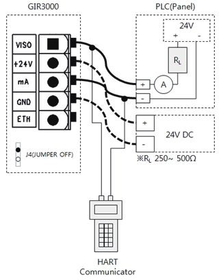
GIR-3000
Instruction Manual
                                                                                                 5. Installation                                                                                             5. Installation           www.gastron.com
                                                                                                                                                                                                                                                 16_17

5.3.3. Wire connection diagram of driving method for                                                                     5.4.2. Setting for Relay mode
4~20mA 3Wire Sink
                                                                                                                         ■ When power is supplied to the power supply terminal on MAIN PCB board after wiring, the following contents can
■ Connect 4-20mA Sink output (+) terminal on PLC                                                                           be checked in LCD unit. After the initial operation power is supplied, stabilization time of about 30 minutes is required,
  side to VISO terminal, and (-) terminal to (24V DC)                                                                       and normal operation occurs from the time of sufficient stabilization.
  (-) terminal. Connect 'mA' terminal of GIR-3000 to
  'GND' terminal. Then connectturn the J1 Jumper
  OFF.

                                                                    [Figure 9. Configuration of 4-20mA 3Wire Sink]

5.4. Configuration of Relay terminal and communication terminal                                                                                                      [Figure 11.Setting for Relay Mode]

5.4.1. Configuration of terminal                                                                                         ■ For driving of Relay of GIR-3000 product, 2 types of Normal open and Normal close are operated. To allow
                                                                                                                           setting of Main PCB에 Relay driving method, Jumper is configured with operation setting as follows.

                                                                                                                          TER. NO.   PIN NO.   TERMINAL NAME                                           MODE 설정
                                                                                                                                        1         TRB OUT                           J3 A-C connection : Contact A ( Normal Open )
                                                                                                                                        2         TRB COM                           J3 B-C connection : Contact B ( Normal Close )
                                                                                                                                        3          AL1 OUT                          J2 A-C connection : Contact A ( Normal Open )
                                                                                                                            CN8
                                                                                                                                        4         AL1 COM                           J2 B-C connection : Contact B( Normal Close )

                                         [Figure 10. Relay and RS485 Terminal]                                                          5          AL2 OUT                         J1 A-C connection : Contact A ( Normal Open )
                                                                                                                                        6         AL2 COM                          J1 B-C connection : Contact B ( Normal Close )
 TER. NO.   PIN NO.   TERMINAL NAME                                      DESCRIPTION
                                                                                                                                                                      [Table 6. Setting for Relay Mode]
               1        TRB OUT       Output mode is determined by TROUBLE RELAY OUTPUT terminal and J3 Jumper setting
               2        TRB COM       TROUBLE RELAY COMMON terminal
                                                                                                                         5.4.3. Setting for RS485 MODBUS
               3        AL1 OUT       Output mode is determined by ALARM1 RELAY OUTPUT terminal, J2 Jumper setting.
   CN8
               4        AL1 COM       ALARM1 RELAY COMMON terminal                                                       ■ MODBUS of GIR-3000 product is an Optional item, and is connected to the receiver unit by the following method.
               5        AL2 OUT       Output mode is determined by ALARM2 RELAY OUTPUT terminal and J1 Jumper setting.
               6        AL2 COM       ALARM2 RELAY COMMON terminal                                                        TER. NO.   PIN NO.   TERMINAL NAME                     RECEIVER TERMINAL NAME                               NOTE
               7         RS485 A      RS485 A terminal                                                                                  7           485A                             'TRXD+' or 'A' or 'P'
   CN3                                                                                                                      CN3
               8         RS485 B      RS485 B terminal                                                                                  8           485B                             'TRXD-' or 'B' or 'N'

                                   [Table 5. Description on Relay and RS485 terminal]                                                                              [Table 7. Description on RS485 terminal]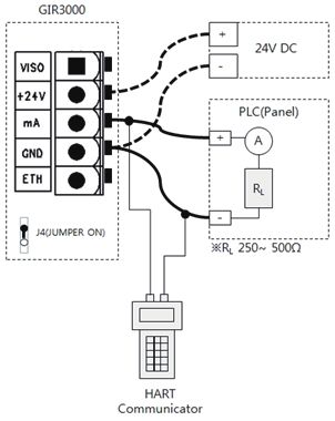
GIR-3000
Instruction Manual
                                                                                                    5. Installation                                                                                         5. Installation               www.gastron.com
                                                                                                                                                                                                                                                    18_19

5.5. Configuration of sensor-connecting terminal                                                                                5.6. Configuration of Remote Type connection
■ IR sensor module (to be referred to as GSA920A hereafter) is connected to the transmitter by using CN No.10                   ■ To remotely configure GSA920A, the sensor is installed by using Junction Box(GDH-1010) of the following form,
  terminal.                                                                                                                       and connection is made to GIR-3000 transmitter by using component terminal inside Junction Box.

                                           [Figure 12. Sensor-connecting terminal]

 TER. NO.     PIN NO.   TERMINAL NAME           COLOR OF SENSOR CABLE                              REMARKS
                1         TRB OUT           TROUBLE RELAY OUT is determined                 +24V sensor power supply
                2         TRB COM          TROUBLE RELAY COMMON terminal              Sensor communication with transmitter                        Wire connection                                                     Wire connection
   CN10                                                                                                                                           diagram for Cable                                                   diagram for Cable
                3          RS485 A                   RS485 A terminal                  Sensor power supply GROUND
                4          RS485 B                   RS485 B terminal                               EARTH                                           (GSA-920A)                                                        (Receive Unit)
                                     [Table 8. Description on sensor-connecting terminal]

■ Configuration of the cable with wire connection to
  GSA920A is as follows.
  - GSA920A module allows configuration of
		 extension cable, and is connected by using
		 CN10 terminal of transmitter.
  - GSA920A Option1 is an exclusive output of                                                                                                                   [Figure 14. Configuration for GSA-920A Remote Type]
		 4-20mA, while the relevant option is used
		 upon sole installation of GSA920A
  - GSA920A Option2 is an exclusive Zero port,
		 while the relevant option is used upon sole
		 installation of GSA920A.
                                                                         [Figure 13. Configuration of connection for GSA920A]
GIR-3000
Instruction Manual
5. Installation 6. Sensor operation Flow www.gastron.com
20_21
5.7. Length of installed cable 6.1. Initial operation state(Power On)
■ The maximum length between GIR-3000 and power supply is determined by the wire specifications. ■ When power is supplied to the power supply terminal on MAIN PCB board after wiring, the following contents can
■ Maximum installation length= VMAXDROP ÷ IMAX ÷ WIRER/m ÷ 2 be confirmed in the LCD unit, a stabilization time of about 30 minutes is required after initial supply of operation
■ VMAXDROP: Maximum Power Loop Voltage Drop (=Power Supply voltage - min operating voltage) power, and normal operation occurs from the time of sufficient stabilization.
■ IMAX: Maximum current value of GIR-3000
■ WIRER/m: The resistance of the wire (ohms/meter value available in wire manufacturer's - When the power supply is turned ON , model name of LCD(OLED) is displayed in the 1st row, while
GIR-3000 firmware version of the transmitter and firmware version of the sensor unit are displayed in the 2nd row.
specification data sheet),
V X.XX / V X.XX - When GSA920A firmware Version is being Read, "Reading" is marked,
■ An example for installation length using 24V power supply and 16AWG is as follows. When Read fails, "Fail" is marked.
■ GIR-3000 minimum operating voltage = 18 Vdc
** SELFTEST ** - SELFTEST is executed for 3 minutes, while '>' character in the 2nd row informs progress state with the
■ VMAXDROP = 24 - 18 = 6V [>>>>>>> 0180] progress count being displayed.
■ IMAX = 0.4A(400mA)
■ 6÷ 0.4÷0.01318÷ 2 = 569.044m ≒ 569m
6.2. Gas Measuring Mode
■ When there is abnormality in SELF TEST after power is turned ON, automatic entry occurs in the following state
of gas measurement.
- When the sensor unit is in waiting state even if progress occurs in a Normal state after SELF TEST,
[ CH4 ]
measured GAS NAME is displayed in the 1st row, while "WAIT" is displayed by the unit of 1 second in
[ WAIT ]%LEL
the 2nd row.
[ CH4 ] - When it is in gas measurement state while being in Normal state, is operates as follows.
[ 0]%LEL - Measured GAS NAME is displayed in the 1st row, while current measured value and unit are displayed
in the 2nd row.
# [ CH4 ]
※ During communication with the sensor unit, '#'character is displayed in the left-side part of GAS NAME.
[ 0]%LEL
※ During HART communication or 485 communication, '*' character is displayed in the left-side part of
[Figure 15. Calculation of length for GIR-3000 installation cable] the 1st row.
*#[ CH4 ]
[ 0]%LEL ※ When ENG. Mode is turned ON, the current temperature is displayed in the left-side part of the 2nd row.
PIN NO. mm2 COPPER RESISTANCE(ohms/m) METERS *#[ CH4 ] - When more than 10% than the High Scale with setting of gas measurement value is inputted, the text of
12 3.31 0.00521 1439 [ OVER]%LEL "OVER" is displayed by the unit of 1 second. At this time, 4~20mA is operated as 22mA.
14 2.08 0.00828 905
- When the gas measurement value is inputted as less than-10%. The text of "UNDER" is displayed by
16 1.31 0.01318 569 *#[ CH4 ]
the unit of 1 second, and 4~20mA is operated as 0mA. (2mA upon use of HART)
18 0.82 0.02095 357 [ UNDER]%LEL
- The relevant function operates when UNDER function is turned ON.
20 0.518 0.0333 225
- When there is abnormality in the device, Fault No. and message are outputted.
FAULT 04
[Table 9. Installation length for GIR-3000 power supply cable] - At this time, 4~20mA is operated as 0mA. (2mA upon use of HART)
> SEN-COMT/O
- The left side is in Fault 4 state occurring when the sensor is not mounted.GIR-3000
Instruction Manual
6. Sensor operation Flow 6. Sensor operation Flow www.gastron.com
22_23
6.3. Operation Flow 6.4. Menu Configuration Table
■ After Power is turned On, undergo the self diagnosis process and enter in the measuring mode. At this time LEVEL2
LEVEL1 DEFAULT
entering inside system mode is possible through the front face key operation. NAME PARAMETER
GROUP OF GAS SEL HC/PROPANE/CO/CO2/
■ Timeout between Level1 and Level2 is 10 seconds, while it is configured as 1 hour in calibration of and Test Mode. HC
(GROUP OF GAS SELECT) SO2/VCM/FREON
■ When "RESET" key is touched in program Mode screen, it is returned to measuring state, while it is returned to the UNIT & TAG SEL.
%/%LEL/PPM/PPB %LEL
upper stage when "RESET" key is touched in each program setting screen. PROGRAMMABLE (UNIT & TAG SELECT)
MODE DECIMAL POINT 0.100/1.00/10.0/100 100
HIGH SCALE ADJ.
1~9999 100
(HIGH SCALEADJUST)
PASSWORD SET 00~99 100
ZERO CALIBRATION
[NO]
[NO, YES]
ZERO GAS
[0]
ZERO PROCESSING
[SUCCESS / FAIL]
CALIBRATION DATA
[ 0]
CALIBRATION CALIBRATION SPAN CALIBRATION
[NO]
MODE [ZERO& SPAN] [NO, YES]
SPAN GAS VALUE
Full Scale의 50%
[ 0]
[CH4] SPAN GAS
000 [ 0]
SPAN PROCESSING
[SUCCESS / FAIL ]
CALIBRATION DATA
[ 0]
ALARM OPERATING [AUTO/MANUAL] AUTO
[Figure 16. Configuration of GIR-3000 mode]
ALARM RELAY TYPE DE-ENERGIZED/ENERGIZED DE-ENERGIZED
FAULT RELAY TYPE DE-ENERGIZED/ENERGIZED DE-ENERGIZED
ITEM NAME DESCRIPTION
ALARM1 TYPE SEL.
Entry function for sensor Mode setting (Input with Magnet-bar for more than 2 seconds in the [INCREASE/ DECREASE] INCREASE
FUNC Function key ALARM PROGRAM (ALARM1 TYPESELECT)
measuring mode) . Entry function for the next stage of Level2 and saving function for setting values
MODE ALARM1 LEVEL ADJ
RESET Reset key Move to the stage before the entered LEVEL [1~Full Scale] 20
(ALARM1 LEVEL ADJUST)
↑ Up key Change the setting value Plus for the next stage mode configured in LEVEL1 and Level2
ALARM1 DEAD BAND [0.0~ Full Scale의10%] 0.0
↓ Down key Change the setting value Minus for the next stage mode configured in LEVEL1 and Level2
ALARM1 RELAY CTL
[ON / OFF] ON
(ALARM RELAY CONTROL)
[Table 10. Description on operation key]You can also read