EVALUATION BOARD MANUAL - FOR RADIO MODULES - MARCH 5, 2019 - Würth Elektronik
←
→
Page content transcription
If your browser does not render page correctly, please read the page content below
E VALUATION           BOARD MANUAL

       F OR RADIO MODULES

WE order code   Former order code   Marketing Name
2607031281001   AMB8636             Thebe-I

                 V ERSION 2.2

                M ARCH 5, 2019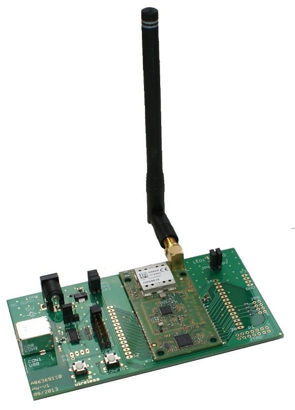
Revision history

 Manual    HW
                     Notes                                      Date
 version   version

 1.0-1.1   2.0          • Initial Version                       June 2017

 2.0       2.0          • New corporate design and structure    December 2018

                        • Added chapter Regulatory compliance
 2.1       2.0            information                           February 2019

 2.2       2.0          • Added Marketing name                  March 2019

Evaluation board manual version 2.2                             © March 2019
www.we-online.com/wireless-connectivity                                      1
Abbreviations and abstract
Abbreviation Name Description
Field Sales Support and sales contact person responsible for
FSE
Engineer limited sales area
HIGH High signal level
LOW Low signal level
Describes everything relating to the wireless
RF Radio frequency
transmission.
Universal
Asynchronous Interface which allows communicating with the
UART
Receiver module of a specific interface.
Transmitter
VDD Supply voltage
Evaluation board manual version 2.2 © March 2019
www.we-online.com/wireless-connectivity 2Contents
1 Supported radio modules 5
2 Functional description 6
2.1 Taking into operation . . . . . . . . . . . . . . . . . . . . . . . . . . . . . . . . 6
3 Development board 7
3.1 Block diagram . . . . . . . . . . . . . . . . . . . . . . . . . . . . . . . . . . . . 7
3.2 Jumpers . . . . . . . . . . . . . . . . . . . . . . . . . . . . . . . . . . . . . . . 8
3.3 Connectors and pin headers . . . . . . . . . . . . . . . . . . . . . . . . . . . 10
3.4 Buttons . . . . . . . . . . . . . . . . . . . . . . . . . . . . . . . . . . . . . . . 11
3.4.1 Reset button . . . . . . . . . . . . . . . . . . . . . . . . . . . . . . . . 11
3.4.2 Config button . . . . . . . . . . . . . . . . . . . . . . . . . . . . . . . . 11
3.5 Function blocks . . . . . . . . . . . . . . . . . . . . . . . . . . . . . . . . . . . 12
3.5.1 Power supply . . . . . . . . . . . . . . . . . . . . . . . . . . . . . . . . 12
3.5.1.1 Self powered, power jack . . . . . . . . . . . . . . . . . . . . . 12
3.5.1.2 Self powered, external power supply trough JP1-2 . . . . . . . 13
3.5.1.3 Bus powered, power supply through USB . . . . . . . . . . . . 13
3.5.2 Current measurement . . . . . . . . . . . . . . . . . . . . . . . . . . . 13
3.5.3 UART / USB . . . . . . . . . . . . . . . . . . . . . . . . . . . . . . . . 14
3.5.4 UART direct . . . . . . . . . . . . . . . . . . . . . . . . . . . . . . . . . 14
3.5.5 Programming interface . . . . . . . . . . . . . . . . . . . . . . . . . . . 14
3.6 Schematic . . . . . . . . . . . . . . . . . . . . . . . . . . . . . . . . . . . . . . 15
3.7 Full layout . . . . . . . . . . . . . . . . . . . . . . . . . . . . . . . . . . . . . . 16
4 Regulatory compliance information 18
4.1 Exemption clause . . . . . . . . . . . . . . . . . . . . . . . . . . . . . . . . . . 18
5 Important information 19
5.1 General customer responsibility . . . . . . . . . . . . . . . . . . . . . . . . . . 19
5.2 Customer responsibility related to specific, in particular safety-relevant appli-
cations . . . . . . . . . . . . . . . . . . . . . . . . . . . . . . . . . . . . . . . . 19
5.3 Best care and attention . . . . . . . . . . . . . . . . . . . . . . . . . . . . . . 19
5.4 Customer support for product specifications . . . . . . . . . . . . . . . . . . . 19
5.5 Product improvements . . . . . . . . . . . . . . . . . . . . . . . . . . . . . . . 20
5.6 Product life cycle . . . . . . . . . . . . . . . . . . . . . . . . . . . . . . . . . . 20
5.7 Property rights . . . . . . . . . . . . . . . . . . . . . . . . . . . . . . . . . . . 20
5.8 General terms and conditions . . . . . . . . . . . . . . . . . . . . . . . . . . . 20
6 Legal notice 21
6.1 Exclusion of liability . . . . . . . . . . . . . . . . . . . . . . . . . . . . . . . . 21
6.2 Suitability in customer applications . . . . . . . . . . . . . . . . . . . . . . . . 21
6.3 Trademarks . . . . . . . . . . . . . . . . . . . . . . . . . . . . . . . . . . . . . 21
6.4 Usage restriction . . . . . . . . . . . . . . . . . . . . . . . . . . . . . . . . . . 21
7 License agreement for Würth Elektronik eiSos GmbH & Co. KG connectivity
product firmware and software 23
7.1 Limited license . . . . . . . . . . . . . . . . . . . . . . . . . . . . . . . . . . . 23
7.2 Usage and obligations . . . . . . . . . . . . . . . . . . . . . . . . . . . . . . . 23
Evaluation board manual version 2.2 © March 2019
www.we-online.com/wireless-connectivity 37.3 Ownership . . . . . . . . . . . . . . . . . . . . . . . . . . . . . . . . . . . . . 24 7.4 Firmware update(s) . . . . . . . . . . . . . . . . . . . . . . . . . . . . . . . . 24 7.5 Disclaimer of warranty . . . . . . . . . . . . . . . . . . . . . . . . . . . . . . . 24 7.6 Limitation of liability . . . . . . . . . . . . . . . . . . . . . . . . . . . . . . . . 25 7.7 Applicable law and jurisdiction . . . . . . . . . . . . . . . . . . . . . . . . . . . 25 7.8 Severability clause . . . . . . . . . . . . . . . . . . . . . . . . . . . . . . . . . 25 7.9 Miscellaneous . . . . . . . . . . . . . . . . . . . . . . . . . . . . . . . . . . . 25 Evaluation board manual version 2.2 © March 2019 www.we-online.com/wireless-connectivity 4
1 Supported radio modules
The evaluation board described in this manual can be used to evaluate the following prod-
ucts:

                Order code         Former order code       Marketing Name
                2607031281001      AMB8636                 Thebe-I

      Order code         Description
      2607031281001      869MHz 500mW proprietary radio module, Band P

                                  Table 1: Compatibility

                                Figure 1: Product image

Evaluation board manual version 2.2                                         © March 2019
www.we-online.com/wireless-connectivity                                                5
2 Functional description The evaluation board offers the user the possibility to develop hard- and software for the compatible radio module. It can be connected to an USB port of a PC. For the connection to a microcontroller system the development board is equipped with a multi-pin connector which is connected to all pins of the RF module. Jumpers allow the module to be disconnected from components which are not required such as the USB inter- face. Feel free to check our youtube channel for video tutorials, hands-ons and webinars related to our products: www.youtube.com/user/WuerthElektronik/videos 2.1 Taking into operation To run the evaluation board place the jumpers on default position as described in chapter 3.2. The corresponding FTDI driver package (www.ftdichip.com/Drivers/VCP.htm) has to be in- stalled on your PC. Connect the power jack or external power supply to the EV board and make sure the VCC is stable and able to reliably supply the module’s static and peak current consumption as specified by the module manual. The next step is to connect the evaluation board to the PC using an USB-cable. In that way a COM port can be detected and installed on your PC. Check the device manager to acquire the COM port name of the EV board. A typical name is "COM12" in Windows systems or /dev/ttyUSB0 in Linux systems. A terminal program (like hterm for Windows) has to be run and the corresponding COM port has to be opened using the default settings of the mounted radio module. After the module is powered through the USB jack or an alternative power supply, the reset button should be pressed to ensure a clean start-up of the module. Please refer to the module reference manual to get the detailed module specific quick start instructions. Evaluation board manual version 2.2 © March 2019 www.we-online.com/wireless-connectivity 6
3 Development board
3.1 Block diagram

                           Figure 2: EV board block diagram

Evaluation board manual version 2.2                           © March 2019
www.we-online.com/wireless-connectivity                                 7
3.2 Jumpers
The following figure shows the default positioning (marked in red) of all jumpers on the EV
board. This section also contains the details to any jumper connection that is supported by
the EV board.
Figure 3: Jumpers, default
Jumper placed
JP1 Description
(default)
1,2 Set Connection of the power supply
Jumper placed
JP2 Description
(default)
Connection for the power supply of the USB
1,2 Set
converter
Jumper placed
JP3 Description
(default)
Connection of the power supply toward the radio
1,2 Set
module (current measurement)
Evaluation board manual version 2.2 © March 2019
www.we-online.com/wireless-connectivity 8Jumper placed
JP4 Description
(default)
Selection of the power supply,
1,2,3 2-3 1-2 USB powered,
2-3 external power supply
Jumper placed
JP5 Description
(default)
1,2 Not set RI host - PJ.2 module
3,4 Not set DCD host - PJ.1 module
5,6 Not set DSR host - PJ.0 module
7,8 Not set DTR host - PJ.3 module
9,10 Set /CTS host - /RTS module
11,12 Set /RTS host - /CTS module
13,14 Set UART RX host - UART TX module
15,16 Set UART TX host - UART RX module
Module
Jumper placed
JP6 pin Description
(default)
function
1,2 TX_LED Set Connection of the red status LED
Module
Jumper placed
JP7 pin Description
(default)
function
1,2 RX_LED Set Connection of the green status LED
Evaluation board manual version 2.2 © March 2019
www.we-online.com/wireless-connectivity 93.3 Connectors and pin headers
Figure 4: Connectors
CON1 Function Description
- USB USB jack for USB interface
CON2 Function Description
- Power supply Power jack for 5V power supply
P1 Function Description
1-14 JTAG JTAG-interface for programming, see chapter 3.5.5
P3 Function Description
1-4 GND Ground
P4 Function Description
1-4 FTDI CBUS 0..3 connector to the 4 CBUS pins of FTDI
Evaluation board manual version 2.2 © March 2019
www.we-online.com/wireless-connectivity 10P6 Function Description
connector to /RESET pin of module,
1 RESET can be connected to P4-1 to provide access to the
/RESET pin through FTDI CBUS0.
Description
3-17 Direct access to the signals of the radio module
20-34 Direct access to the signals of the radio module
3.4 Buttons
3.4.1 Reset button
Internally the active low reset input of the microprocessor is connected via a RC combina-
tion with the power supply to ensure a proper startup of the module. The module provides a
/RESET pin that is connected to this button so the module can be restarted properly. Please
refer to the module specific manual for detailed information.
The reset is also available on pin 19 (P8) and P6.
3.4.2 Config button
By means of the Config pushbutton the module can be switched between the command
mode and transparent mode.
The switching takes place after recognition of a falling edge on the /CONFIG pin (pushing
Config button) and is acknowledged through a respective command. The switching of the
modes can only take place while no data is being received via RF (/RTS has to be low).
Please refer to the module specific manual for detailed information.
Evaluation board manual version 2.2 © March 2019
www.we-online.com/wireless-connectivity 113.5 Function blocks
3.5.1 Power supply
Figure 5: Power Supply Circuit
Figure 6: Power Supply Layout
3.5.1.1 Self powered, power jack
Make sure JP4 is in default position (2-3, "self powered") and JP2 jumper set.
The development board can be operated by connecting a 5V voltage source to the power
jack. Pay special attention to the polarity before connecting the power jack to the board.
Evaluation board manual version 2.2 © March 2019
www.we-online.com/wireless-connectivity 12If the power supply is connected and the bridges on JP1, JP2, JP3 and JP4 are set correctly (as in the factory state), then the power LED3 should be ON. The integrated voltage regulator regulates the connected 5V down to 3.3V with which the remaining parts of the circuit are supplied. Make sure that the power jack (or external power supply) is connected to the module and VCC is stable before the USB is connected to a PC. 3.5.1.2 Self powered, external power supply trough JP1-2 Remove the JP1 jumper. JP1 should not be set in order to avoid voltage on the output of the integrated voltage regu- lator. The radio module may be powered via pin 2 of JP1 (JP1-2) behind the voltage regulator. Ap- plying GND to the board can take place via any P3 pin. Using the USB-interface in parallel to this power supply method (with JP2 jumper set) the voltage range of the external supply has to be kept in between 3.0V and 3.6V to operate the USB converter in its specified range. When the power is connected the power LED3 will be on. Make sure that the power jack (or external power supply) is connected to the module and VCC is stable before the USB is connected to a PC. 3.5.1.3 Bus powered, power supply through USB The radio module may be powered via USB connector (requires the JP4 to be placed at 1-2). As the module’s peak current in TX mode is higher (see product specific manual) than the "Max Bus Power" configured in the FTDI IC this method is not recommended to be used as it may damage the connected PC permanently. Supplying the board solely via USB is only recommended in case of receiving. When send- ing with high output power the supply of the board must be done via the power jack with jumper setting "self" to avoid damaging the USB-host through to too high power drain. 3.5.2 Current measurement JP3 can be used to measure the power consumption of the module. By default a bridge is set on JP3 to close the circuit. Remove the bridge and connect a current meter in place of the jumper to measure the power consumption of the module. If the meter is not attached and the bridge is not set, the module will not receive supply voltage. However, the power LED may be active, as it is connected prior to the current mea- surement bridge in order not to distort the module’s power consumption. Parts connected to the module, such as LEDs, can be separated from the module via JP6 and JP7. Power may also be supplied to the module via JP3 (2.0V - 3.6V). However, in this Evaluation board manual version 2.2 © March 2019 www.we-online.com/wireless-connectivity 13
case the USB converter will not be powered.

3.5.3 UART / USB
The UART of the module can be connected to the USB converter by setting the according
jumpers (see defaults) to JP5 and is available on the USB jack so that the module can be
connected directly to a PC or host . Using the FTDI-driver the PC will show a virtual COM-
Port which can be used to communicate with the module.
Verify that the JP2 jumper is mounted (important for correct IO levels) and make sure that
the power jack (or external power supply) is connected to the module and VCC is stable
before the USB is connected to a PC.

                                      Figure 7: USB

3.5.4 UART direct
If a microcontroller is to be connected to the module, remove the bridges on JP5. The UART
can be connected directly on the pin strip JP5 (all odd numbered pins). The module RXD
line must be handled accordingly by your host (i.e. pulled up while inactive and during mod-
ule boot-up).

Beware of IO level incompatibility. The host must obey the values stated in the module’s
manual. Especially the IO level restrictions must be implemented by a host system (i.e. us-
ing a level shifter to use the allowed IO levels).

3.5.5 Programming interface
The evaluation board provides a 2*7 pin connector (P1) in 2.54 RM to connect directly to a
JTAG flash adapter used for development. Please take care of the correct mounting of the
flash adapter (Pin 1 is marked as such).

Evaluation board manual version 2.2                                           © March 2019
www.we-online.com/wireless-connectivity                                                  14
3.6 Schematic
Figure 8: Wiring diagram
Evaluation board manual version 2.2 © March 2019
www.we-online.com/wireless-connectivity 153.7 Full layout
Figure 9: Assembly diagram
Evaluation board manual version 2.2 © March 2019
www.we-online.com/wireless-connectivity 16Figure 10: Top and Bottom Layer Evaluation board manual version 2.2 © March 2019 www.we-online.com/wireless-connectivity 17
4 Regulatory compliance information
Pursuant to Article 1 (2.) of the EU directive 2014/53/EU, Article 1 (2.) the directive does
not apply to equipment listed in Annex I (4.): custom-built evaluation kits destined for profes-
sionals to be used solely at research and development facilities for such purposes.

4.1 Exemption clause
Relevant regulation requirements are subject to change. Würth Elektronik eiSos does not
guarantee the accuracy of the before mentioned information. Directives, technical standards,
procedural descriptions and the like may be interpreted differently by the national authori-
ties. Equally, the national laws and restrictions may vary with the country. In case of doubt
or uncertainty, we recommend that you consult with the authorities or official certification
organizations of the relevant countries. Würth Elektronik eiSos is exempt from any respon-
sibilities or liabilities related to regulatory compliance.

Notwithstanding the above, Würth Elektronik eiSos makes no representations and war-
ranties of any kind related to their accuracy, correctness, completeness and/or usability for
customer applications. No responsibility is assumed for inaccuracies or incompleteness.

Evaluation board manual version 2.2                                              © March 2019
www.we-online.com/wireless-connectivity                                                      18
5 Important information
The following conditions apply to all goods within the wireless connectivity product range of
Würth Elektronik eiSos GmbH & Co. KG :

5.1 General customer responsibility
Some goods within the product range of Würth Elektronik eiSos GmbH & Co. KG contain
statements regarding general suitability for certain application areas. These statements
about suitability are based on our knowledge and experience of typical requirements con-
cerning the areas, serve as general guidance and cannot be estimated as binding state-
ments about the suitability for a customer application. The responsibility for the applicability
and use in a particular customer design is always solely within the authority of the customer.
Due to this fact, it is up to the customer to evaluate, where appropriate to investigate and to
decide whether the device with the specific product characteristics described in the product
specification is valid and suitable for the respective customer application or not. Accordingly,
the customer is cautioned to verify that the documentation is current before placing orders.

5.2 Customer responsibility related to specific, in particular
    safety-relevant applications
It has to be clearly pointed out that the possibility of a malfunction of electronic compo-
nents or failure before the end of the usual lifetime cannot be completely eliminated in the
current state of the art, even if the products are operated within the range of the specifica-
tions. The same statement is valid for all software and firmware parts contained in or used
with or for products in the wireless connectivity product range of Würth Elektronik eiSos
GmbH & Co. KG . In certain customer applications requiring a high level of safety and espe-
cially in customer applications in which the malfunction or failure of an electronic component
could endanger human life or health, it must be ensured by most advanced technological
aid of suitable design of the customer application that no injury or damage is caused to third
parties in the event of malfunction or failure of an electronic component.

5.3 Best care and attention
Any product-specific datasheets, manuals, application notes, PCN’s, warnings and cautions
must be strictly observed in the most recent versions and matching to the products firmware
revisions. This documents can be downloaded from the product specific sections on the
wireless connectivity homepage.

5.4 Customer support for product specifications
Some products within the product range may contain substances, which are subject to re-
strictions in certain jurisdictions in order to serve specific technical requirements. Necessary
information is available on request. In this case, the field sales engineer or the internal sales
person in charge should be contacted who will be happy to support in this matter.

Evaluation board manual version 2.2                                               © March 2019
www.we-online.com/wireless-connectivity                                                       19
5.5 Product improvements Due to constant product improvement, product specifications may change from time to time. As a standard reporting procedure of the Product Change Notification (PCN) according to the JEDEC-Standard, we inform about major changes in hard- or firmware. In case of further queries regarding the PCN, the field sales engineer, the internal sales person or the technical support team in charge should be contacted. The basic responsibility of the customer as per section 5.1 and 5.2 remains unaffected. 5.6 Product life cycle Due to technical progress and economical evaluation we also reserve the right to discontin- ue production and delivery of products. As a standard reporting procedure of the Product Termination Notification (PTN) according to the JEDEC-Standard we will inform at an early stage about inevitable product discontinuance. According to this, we cannot ensure that all products within our product range will always be available. Therefore, it needs to be verified with the field sales engineer or the internal sales person in charge about the current product availability expectancy before or when the product for application design-in disposal is con- sidered. The approach named above does not apply in the case of individual agreements deviating from the foregoing for customer-specific products. 5.7 Property rights All the rights for contractual products produced by Würth Elektronik eiSos GmbH & Co. KG on the basis of ideas, development contracts as well as models or templates that are subject to copyright, patent or commercial protection supplied to the customer will remain with Würth Elektronik eiSos GmbH & Co. KG . Würth Elektronik eiSos GmbH & Co. KG does not warrant or represent that any license, either expressed or implied, is granted under any patent right, copyright, mask work right, or other intellectual property right relating to any combination, application, or process in which Würth Elektronik eiSos GmbH & Co. KG components or services are used. 5.8 General terms and conditions Unless otherwise agreed in individual contracts, all orders are subject to the current ver- sion of the "General Terms and Conditions of Würth Elektronik eiSos Group", last version available at www.we-online.com. Evaluation board manual version 2.2 © March 2019 www.we-online.com/wireless-connectivity 20
6 Legal notice
6.1 Exclusion of liability
Würth Elektronik eiSos GmbH & Co. KG considers the information in this document to be
correct at the time of publication. However, Würth Elektronik eiSos GmbH & Co. KG re-
serves the right to modify the information such as technical specifications or functions of
its products or discontinue the production of these products or the support of one of these
products without any written announcement or notification to customers. The customer must
make sure that the information used corresponds to the latest published information. Würth
Elektronik eiSos GmbH & Co. KG does not assume any liability for the use of its product-
s. Würth Elektronik eiSos GmbH & Co. KG does not grant licenses for its patent rights or
for any other of its intellectual property rights or third-party rights. Notwithstanding anything
above, Würth Elektronik eiSos GmbH & Co. KG makes no representations and/or warranties
of any kind for the provided information related to their accuracy, correctness, completeness,
usage of the products and/or usability for customer applications. Information published by
Würth Elektronik eiSos GmbH & Co. KG regarding third-party products or services does not
constitute a license to use such products or services or a warranty or endorsement thereof.

6.2 Suitability in customer applications
The customer bears the responsibility for compliance of systems or units, in which Würth
Elektronik eiSos GmbH & Co. KG products are integrated, with applicable legal regulation-
s. Customer acknowledges and agrees that it is solely responsible for compliance with all
legal, regulatory and safety-related requirements concerning its products, and any use of
Würth Elektronik eiSos GmbH & Co. KG components in its applications, notwithstanding
any applications-related in-formation or support that may be provided by Würth Elektronik
eiSos GmbH & Co. KG . Customer represents and agrees that it has all the necessary ex-
pertise to create and implement safeguards which anticipate dangerous consequences of
failures, monitor failures and their consequences lessen the likelihood of failures that might
cause harm and take appropriate remedial actions. The customer will fully indemnify Würth
Elektronik eiSos GmbH & Co. KG and its representatives against any damages arising out
of the use of any Würth Elektronik eiSos GmbH & Co. KG components in safety-critical
applications.

6.3 Trademarks
AMBER wireless is a registered trademark of Würth Elektronik eiSos GmbH & Co. KG . All
other trademarks, registered trademarks, and product names are the exclusive property of
the respective owners.

6.4 Usage restriction
Würth Elektronik eiSos GmbH & Co. KG products have been designed and developed for
usage in general electronic equipment only. This product is not authorized for use in equip-
ment where a higher safety standard and reliability standard is especially required or where
a failure of the product is reasonably expected to cause severe personal injury or death,
unless the parties have executed an agreement specifically governing such use. Moreover,

Evaluation board manual version 2.2                                               © March 2019
www.we-online.com/wireless-connectivity                                                       21
Würth Elektronik eiSos GmbH & Co. KG products are neither designed nor intended for use
in areas such as military, aerospace, aviation, nuclear control, submarine, transportation
(automotive control, train control, ship control), transportation signal, disaster prevention,
medical, public information network etc. . Würth Elektronik eiSos GmbH & Co. KG must be
informed about the intent of such usage before the design-in stage. In addition, sufficient
reliability evaluation checks for safety must be performed on every electronic component,
which is used in electrical circuits that require high safety and reliability function or perfor-
mance. By using Würth Elektronik eiSos GmbH & Co. KG products, the customer agrees to
these terms and conditions.

Evaluation board manual version 2.2                                               © March 2019
www.we-online.com/wireless-connectivity                                                       22
7 License agreement for Würth Elektronik eiSos
  GmbH & Co. KG connectivity product firmware and
  software
Agreement between You and Würth Elektronik eiSos GmbH & Co. KG

The following terms of this license agreement for the usage of the Würth Elektronik eiSos
GmbH & Co. KG wireless connectivity product firmware are a legal agreement between you
and Würth Elektronik eiSos GmbH & Co. KG and/or its subsidiaries and affiliates (collective-
ly, "Würth Elektronik eiSos "). You hereby agree that this license agreement is applicable
to the product and the incorporated software and firmware (collectively, "Firmware") made
available by Würth Elektronik eiSos in any form, including but not limited to binary, exe-
cutable or source code form.
The Firmware included in any Würth Elektronik eiSos wireless connectivity product is pur-
chased to you on the condition that you accept the terms and conditions of this license
agreement. You agree to comply with all provisions under this license agreement.

7.1 Limited license
Würth Elektronik eiSos hereby grants you a limited, non-exclusive, non-transferable and
royalty-free license to use the Firmware under the conditions that will be set forth in this
license agreement. You are free to use the provided Firmware only in connection with one of
the products from Würth Elektronik eiSos to the extent described in this license agreement.
You are not entitled to change or alter the provided Firmware.
You are not entitled to transfer the Firmware in any form to third parties without prior written
consent of Würth Elektronik eiSos .
You are not allowed to reproduce, translate, reverse engineer, read out, decompile, disas-
semble or create derivative works of the incorporated Firmware in whole or in part.
No more extensive rights to use and exploit the Firmware granted to you.

7.2 Usage and obligations
The responsibility for the applicability and use of the Würth Elektronik eiSos wireless con-
nectivity product with the incorporated Firmware in a particular customer design is always
solely within the authority of the customer. Due to this fact, it is up to you to evaluate and
investigate, where appropriate, and to decide whether the device with the specific product
characteristics described in the product specification is valid and suitable for your respective
application or not.
You are responsible for using the Würth Elektronik eiSos Product with the incorporated
Firmware in compliance with all applicable product liability and product safety laws. You
acknowledge to minimize the risk of loss and harm to individuals and bear the risk for failure
leading to personal injury or death due to your usage of the product.
Würth Elektronik eiSos ’ products with the incorporated Firmware are not authorized for use
in safety-critical applications, or where a failure of the product is reasonably expected to
cause severe personal injury or death. Moreover, Würth Elektronik eiSos ’ products with the
incorporated Firmware are neither designed nor intended for use in areas such as military,
aerospace, aviation, nuclear control, submarine, transportation (automotive control, train

Evaluation board manual version 2.2                                              © March 2019
www.we-online.com/wireless-connectivity                                                      23
control, ship control), transportation signal, disaster prevention, medical, public information
network etc. You shall inform Würth Elektronik eiSos about the intent of such usage before
design-in stage. In certain customer applications requiring a very high level of safety and
in which the malfunction or failure of an electronic component could endanger human life or
health, you must ensure to have all necessary expertise in the safety and regulatory ramifica-
tions of your applications. You acknowledge and agree that you are solely responsible for all
legal, regulatory and safety-related requirements concerning your products and any use of
Würth Elektronik eiSos ’ products with the incorporated Firmware in such safety-critical ap-
plications, notwithstanding any applications-related information or support that may be pro-
vided by Würth Elektronik eiSos . YOU SHALL INDEMNIFY WÜRTH ELEKTRONIK EISOS
AGAINST ANY DAMAGES ARISING OUT OF THE USE OF WÜRTH ELEKTRONIK EISOS’
PRODUCTS WITH THE INCORPORATED FIRMWARE IN SUCH SAFETY-CRITICAL AP-
PLICATIONS.

7.3 Ownership
The incorporated Firmware created by Würth Elektronik eiSos is and will remain the exclu-
sive property of Würth Elektronik eiSos .

7.4 Firmware update(s)
You have the opportunity to request the current and actual firmware for a bought wireless
connectivity Product within the time of warranty. However, Würth Elektronik eiSos has no
obligation to update a modules firmware in their production facilities, but can offer this as a
service on request. The upload of firmware updates falls within your responsibility, e.g. via
ACC or another software for firmware updates. Firmware updates will not be communicated
automatically. It is within your responsibility to check the current version of a firmware in the
latest version of the product manual on our website. The revision table in the product manual
provides all necessary information about firmware updates. There is no right to be provided
with binary files, so called "firmware images", those could be flashed through JTAG, SWD,
Spi-Bi-Wire, SPI or similar interfaces.

7.5 Disclaimer of warranty
THE FIRMWARE IS PROVIDED "AS IS". YOU ACKNOWLEDGE THAT WÜRTH ELEK-
TRONIK EISOS MAKES NO REPRESENTATIONS AND WARRANTIES OF ANY KIND
RELATED TO, BUT NOT LIMITED TO THE NON-INFRINGEMENT OF THIRD PARTIES’
INTELLECTUAL PROPERTY RIGHTS OR THE MERCHANTABILITY OR FITNESS FOR
YOUR INTENDED PURPOSE OR USAGE. WÜRTH ELEKTRONIK EISOS DOES NOT
WARRANT OR REPRESENT THAT ANY LICENSE, EITHER EXPRESS OR IMPLIED, IS
GRANTED UNDER ANY PATENT RIGHT, COPYRIGHT, MASK WORK RIGHT, OR OTHER
INTELLECTUAL PROPERTY RIGHT RELATING TO ANY COMBINATION, MACHINE, OR
PROCESS IN WHICH THE WÜRTH ELEKTRONIK EISOS’ PRODUCT WITH THE INCOR-
PORATED FIRMWARE IS USED. INFORMATION PUBLISHED BY WÜRTH ELEKTRONIK
EISOS REGARDING THIRD-PARTY PRODUCTS OR SERVICES DOES NOT CONSTI-
TUTE A LICENSE FROM WÜRTH ELEKTRONIK EISOS TO USE SUCH PRODUCTS OR
SERVICES OR A WARRANTY OR ENDORSEMENT THEREOF.

Evaluation board manual version 2.2                                               © March 2019
www.we-online.com/wireless-connectivity                                                       24
7.6 Limitation of liability
Any liability not expressly provided by Würth Elektronik eiSos shall be disclaimed.
You agree to hold us harmless from any third-party claims related to your usage of the
Würth Elektronik eiSos ’ products with the incorporated Firmware. Würth Elektronik eiSos
disclaims any liability for any alteration, development created by you or your customers as
well as for any combination with other products.

7.7 Applicable law and jurisdiction
Applicable law to this license agreement shall be the laws of the Federal Republic of Ger-
many. Any dispute, claim or controversy arising out of or relating to this license agreement
shall be resolved and finally settled by the court competent for the location of Würth Elek-
tronik eiSos ’ registered office.

7.8 Severability clause
If a provision of this license agreement is or becomes invalid, unenforceable or null and void,
this shall not affect the remaining provisions of the agreement. The parties shall replace any
such provisions with new valid provisions that most closely approximate the purpose of the
agreement.

7.9 Miscellaneous
This license agreement constitutes the entire understanding and merges all prior discussions
between the parties relating to this license agreement.
No ancillary verbal agreements have been made and no such agreements shall be valid.
Any additions and amendments to this license agreement shall require the written form in
order to be binding.
We recommend you to be updated about the status of new firmware, which is available
on our website or in our data sheet, and to implement new firmware in your device where
appropriate. In case only firmware is provided, we expressly exclude the automatic receipt
of PCN information. Thus, new firmware will also not be provided automatically.
By ordering a wireless connectivity Product, you accept this license agreement in all terms.

Evaluation board manual version 2.2                                             © March 2019
www.we-online.com/wireless-connectivity                                                     25
List of Figures
   1    Product image . . . . .     .   .   .   .   .   .   .   .   .   .   .   .   .   .   .   .   .   .   .   .   .   .   .   .   .   .   .   .   .   .    5
   2    EV board block diagram      .   .   .   .   .   .   .   .   .   .   .   .   .   .   .   .   .   .   .   .   .   .   .   .   .   .   .   .   .   .    7
   3    Jumpers, default . . . .    .   .   .   .   .   .   .   .   .   .   .   .   .   .   .   .   .   .   .   .   .   .   .   .   .   .   .   .   .   .    8
   4    Connectors . . . . . . .    .   .   .   .   .   .   .   .   .   .   .   .   .   .   .   .   .   .   .   .   .   .   .   .   .   .   .   .   .   .   10
   5    Power Supply Circuit . .    .   .   .   .   .   .   .   .   .   .   .   .   .   .   .   .   .   .   .   .   .   .   .   .   .   .   .   .   .   .   12
   6    Power Supply Layout . .     .   .   .   .   .   .   .   .   .   .   .   .   .   .   .   .   .   .   .   .   .   .   .   .   .   .   .   .   .   .   12
   7    USB . . . . . . . . . . .   .   .   .   .   .   .   .   .   .   .   .   .   .   .   .   .   .   .   .   .   .   .   .   .   .   .   .   .   .   .   14
   8    Wiring diagram . . . . .    .   .   .   .   .   .   .   .   .   .   .   .   .   .   .   .   .   .   .   .   .   .   .   .   .   .   .   .   .   .   15
   9    Assembly diagram . . .      .   .   .   .   .   .   .   .   .   .   .   .   .   .   .   .   .   .   .   .   .   .   .   .   .   .   .   .   .   .   16
   10   Top and Bottom Layer .      .   .   .   .   .   .   .   .   .   .   .   .   .   .   .   .   .   .   .   .   .   .   .   .   .   .   .   .   .   .   17

List of Tables
   1    Compatibility . . . . . . . . . . . . . . . . . . . . . . . . . . . . . . . . . . . .                                                                5

Evaluation board manual version 2.2                                                                                                     © March 2019
www.we-online.com/wireless-connectivity                                                                                                                     26
more than you expect

    Internet                               Monitoring   Automated Meter
    of Things                              & Control    Reading

Contact:
Würth Elektronik eiSos GmbH & Co. KG
Division Wireless Connectivity & Sensors

Rudi-Schillings-Str. 31
54296 Trier
Germany

Tel.: +49 651 99355-0
Fax.: +49 651 99355-69
www.we-online.com/wireless-connectivity
You can also read