POWER OVER ETHERNET (POE) DEVICES SETTING THE STANDARD IN SYNCHRONIZED TIME - AMERICAN TIME
←
→
Page content transcription
If your browser does not render page correctly, please read the page content below

Power over Ethernet (PoE) Devices
       Installation & Operation Manual
                H005042_R05 07.2021

                         Setting the Standard
                       in Synchronized Time.
Safety Precautions

All electrical power wiring connected to the Power over Ethernet Clocks and Devices must be installed by
qualified persons in conformance with applicable national and local electrical codes. Improper installation of
this equipment can result in electrical shock and fire.
The PoE clock/device should be installed in a secure location protected from:
        —Physical damage
        —Water, including condensation
Operation of this product in a manner inconsistent with the instructions in the manual may result in personal
injury and damage to the product and will void the warranty.

                                                American Time
                                       140 3rd Street South, PO Box 707
                                            Dassel, MN 55325-0707

                                               Phone: 800-328-8996
                                                 Fax: 800-789-1882
                                               american-time.com

                    ©2021 American Time PoE Clocks & Auxiliary Devices Installation & Operation Manual           2
Table of Contents
Introduction................................................................................................................................................................ 4
Specifications......................................................................................................................................................... 5-7
        Analog Clocks......................................................................................................................................................................... 5
        Digital Clocks.......................................................................................................................................................................... .6
        Digital Clock Relay................................................................................................................................................................. 7
Installation...............................................................................................................................................................8-12
        Standalone Relay............................................................................................................................................. 8
        Analog Clocks......................................................................................................................................................................... 9
        Digital Clocks............................................................................................................................................. 10-12
Activation on inCloud................................................................................................................................................13
Network Clock Connect...................................................................................................................................... 14-23
        System Requirements.....................................................................................................................................14
        Installation........................................................................................................................................................14
        Login.................................................................................................................................................................14
        Main Screen............................................................................................................................................... 15-16
        Configuration.............................................................................................................................................. .17-23
		          Clock Tab......................................................................................................................................................................... 17
		          Time Zone Tab................................................................................................................................................................18
		          DST Tab............................................................................................................................................................................18
		          Network Tab....................................................................................................................................................................19
		          Buzzer Tab.......................................................................................................................................................................20
		          Manuf Tab........................................................................................................................................................................20
		          Schedule Editor........................................................................................................................................................21-22
		          Event Editor.............................................................................................................................................................. 22-23
Troubleshooting: DHCP............................................................................................................................................................ 24-25
Troubleshooting: Clock Time.........................................................................................................................................................26
Appendix A: NIST Time Servers....................................................................................................................................................27
Appendix B: Supported Time Zones...........................................................................................................................................27
Appendix C: Buzzer/Relay Scheduling Examples........................................................................................................... 28-29
Appendix D: Brightness Control Scheduling Example.................................................................................................. 30-31
Appendix E: Timer Control Station Operation.........................................................................................................................13

                                  ©2021 American Time PoE Clocks & Auxiliary Devices Installation & Operation Manual                                                                                  3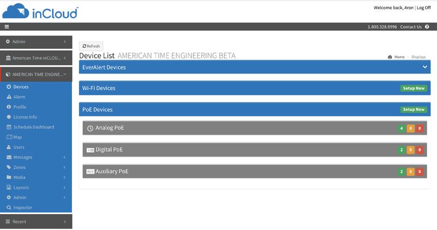
Introduction
Power over Ethernet (PoE) provides an accurate synchronized time source. PoE and Simple Network Time Protocol
(SNTP) are used to make installation and setup as simple as possible. All you need to do is connect the clock or
device to a PoE enabled Local Area Network (LAN) Ethernet drop.
PoE
Power over Ethernet (PoE) describes a system that passes electrical power, along with data, through Ethernet
cabling. Power may come from a power supply within a networking device such as a PoE switch or it may be
injected into the Ethernet cable using a midspan injector.
There are several advantages for using PoE. PoE eliminates the need to run AC power cables for certain devices.
Instead, the more cost effective category 5 or 6 cable is run for PoE devices. Also, since PoE is symmetrically
distributed, the power source may be determined after the cables are ran.
PoE clocks require connection to a PoE enabled LAN. In a typical installation, a PoE switch or a PoE injector would
be used to power your PoE clock.
Network
These PoE Devices are plug and play on networks with Dynamic Hosting Configuration Protocol (DHCP). A NIST
time server is used for the default time server but may be changed using the Network Clock Connect application or
the configuration web page.

The clocks may also be configured using static IP addresses.

inCloud Management Portal
PoE devices are configured for use with American Time's inCloud Management Portal. With the inCloud
management portal you can set up, monitor and manage your American Time devices easily and from anywhere.
inCloud is a cloud-based management interface, featuring a status dashboard for monitoring your devices,
configuration profiles to ensure devices are utilizing the same settings, and network/connectivity information.

The designated site manager for your location should have received a welcome e-mail with a link to inCloud and
initial log-in information after placing the order for your devices. Logging in to inCloud will be required to complete
setup of the devices; ensure that your site manager is available during the configuration and installation process.

To log in to inCloud, visit incloud.american-time.com and log in using the credentials provided in your American
Time welcome e-mail.

NOTE: For non-inCloud customers, clocks can still be configured using the Network Clock Connect
application described in this manual.

Certifications (Clocks Only)
• Electromagnetic Emissions

             EN 55032:2012/AC:2013 Class B

             FCC 15.107:2018 Class B

             FCC 15.109:2018 Class B

             ICES-003:2016 Class B

• Electromagnetic Immunity

             EN 55024:2010

• Safety

		           CB

                    ©2021 American Time PoE Clocks & Auxiliary Devices Installation & Operation Manual                    4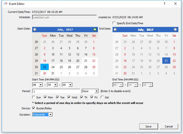
Specifications
Power over Ethernet Analog Clocks
Available in the following configurations:
PEXXXXXXXXB – Buzzer version
PEXXXXXXXX – Analog Version
Note: The X's are model dependent
Optional Products:
PoE Injector, single port – TMA200
USB Drive with Network Clock Connect Software – H004167B-POE
Security Bracket for analog clocks (part number varies by size)
Features:
         •   Time Zone Management
         •   Supports up to 10 SNTP servers for redundancy
         •   Supports Daylight Saving Time
         •   Power over Ethernet (IEEE802.3af)
         •   DHCP or Static IP addressing
         •   Network Clock Connect configuration
         •   Status LED indicator
         •   Scheduling (Buzzer version) - maximum of 100 scheduled events
Dimensions: Varies by model
Power Consumption: PoE, IEEE802.3af compliant, 1W
Operating Temperature: 32˚F to 104˚F (0˚ to 40˚C)
Operating Humidity: 95% maximum, non-condensing
Accuracy: ±1 second
Buzzer Option Specifications:
Sound Level: 65dBA at 10 feet

                    ©2021 American Time PoE Clocks & Auxiliary Devices Installation & Operation Manual   5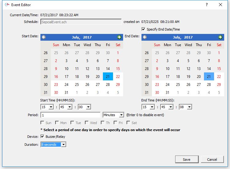
Specifications

Power over Ethernet Digital/Calendar Clocks
Available in the following configurations:
PGEXXXXXE- Base version
PGEXXXXXEB - Base w/Buzzer
PGEXMXXXE - Base w/Calendar
PGEXMXXXEB - Base w/Calendar & Buzzer
Note: The X's are model dependent

Optional Products:
PoE Injector, single port – TMA200
USB Drive with Network Clock Connect Software – H004167B-POE
Timer Control Station – ATSTCS
Double Dials – (Ceiling or Wall)
Features:
         •    Time Zone Management
         •    Supports up to 10 SNTP servers for redundancy
         •    Supports Daylight Saving Time
         •    12/24 Hour Mode with PM indicator
         •    Power over Ethernet (IEEE802.3af)
         •    DHCP or Static IP addressing
         •    Network Clock Connect configuration
         •    Programmable Brightness Controls (High, Low, Sleep, Off)
         •    Elapsed Time Indication (ETI) with Code Blue
         •    Countdown Timer
         •    Scheduling (Buzzer/Relay) - maximum of 100 scheduled events
         •    Calendar Clock Display Modes:
                MM:DD:YY           DD:MM:YY         YY:MM:DD           M:D:YY           D:M:YY              YY:M:D
         •    Configurable date/time toggle durations
Specifications:
Dimensions:
Digital Clocks: 2.5" display: 4 & 6 digit - 12.250” x 5.1875” x 2.5”d
                4" display: 4 digit - 12.250” x 6.8750” x 2.5”d
                4" display: 6 digit - 17.250” x 6.8750” x 2.5”d
ATSTCS: Timer Control Station: 4.63”h X 4.56”w X 1.25”deep
Weight: Digital Clock: Varies by model
         ATSTCS Timer Control Station: 0.27 lb.
Power Consumption: PoE, IEEE 802.3af compliant
       Size   Digits    Color   Power average      Power Max         Size   Digits   Color   Power average       Power Max
                        Green        5.0W             6.0W                           Green        5.0W               6.0W
                4                                                             4
                         Red         5.5W             7.0W                            Red         5.5W               7.0W
       2.5”                                                            4”
                        Green        6.0W             7.0W                           Green        6.0W               7.0W
                6                                                             6
                         Red         6.5W             8.0W                            Red         6.5W               8.0W

                       ©2021 American Time PoE Clocks & Auxiliary Devices Installation & Operation Manual                    6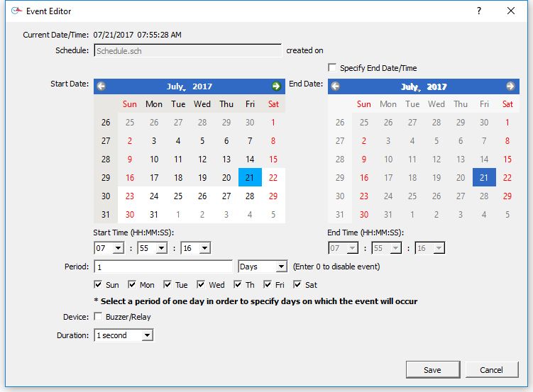
Specifications

Distance of ATSTCS from Digital Clock/Timer: 30-ft maximum with 22 AWG stranded wire with minimum 1/32”
thick insulation
Code Blue Circuits: 3.0mA. max. @ 12vac/vdc-30vac/vdc
Operating Temperature: 32˚F to 104˚F (0˚ to 40˚C)
Operating Humidity: 95% maximum, non-condensing
OPERATION
Modes Available:12 hour or 24-hour synchronized. Incrementing timer with programmable preset value and start/stop
capability. Decrementing timer with programmable preset value and start/stop capability. Code Blue incrementing timer
Accuracy: ±1 second
Indications: ATSTCS Control Station: 2 second audible alarm
Buzzer Option Specifications:
        Sound Level: 65dBA at 10 feet
Digital Clock Relay Option Specifications:
        Dry contact closure
        Wiring for the internal relay closure:
		              Maximum Voltage: 60vdc, 125vac
		              Maximum Switched Current: 1A
		              Maximum Carrying Current: 1A

                      Relay Connection
                      Diagram
                                                         +
                                                             Activate
                                                         –                               1 Normally closed
                                                          ALARM                          2 Common
                                                          SYSTEM
                                                                                         3 Normally open
                                                              Comm

                                                                            Connector
                                                                            Relay

                                                                                     3
                                                                                                1

                         RELAY

                    ©2021 American Time PoE Clocks & Auxiliary Devices Installation & Operation Manual                  7
PoE Standalone Relay Information

The PoE Standalone Relay is a scheduleable relay device which can be used to trigger low-power devices such as
bells, strobes, and horns, or as a controller for a higher-powered relay to control larger devices.
The Standalone Relay can be controlled and scheduled using either the inCloud Management Portal or the
Network Clock Connect Application.
Before installing, verify the network infrastructure with the Network Administrator. The Power over Ethernet (PoE)
power solution and Dynamic Host Configuration Protocol (DHCP) settings should be determined. The PoE device
locations and cabling routes should also be determined prior to installation.
     1.   Mount the relay in the desired location, using the mounting hole flanges on the sides of the relay.
     2. inCloud users should activate their devices on the Management Portal at this time. Reference step 6 in
        the relay quick start guide for instructions on inCloud activation.
     3. Apply power to the relay by connecting a CAT 5 or higher Ethernet patch cable from a PoE switch or
        single injector to the PoE jack on the relay.
          •   PoE Switch: Check with the Network Administrator for infrastructure needs. This part is not supplied
              by American Time.
          •   PoE Injector (TMA200): This is an optional power source that may be purchased from American Time.
     4. The Status LED will indicate the clocks status as follows:
          •   Flashing Red: Attempting to acquire an IP address using DHCP
          •   Continuous Red: IP address successfully acquired
          •   Flashing Orange: Attempting SNTP sync
          •   Continuous Orange: SNTP sync failed
          •   Flashing Green: Communicating with inCloud management portal
          •   Continuous Green: Successful SNTP sync
To operate the relay, inCloud users should reference the inCloud Scheduler User Guide. Non-inCloud users can
schedule relay function using Network Clock Connect; see the Network Clock Connect section in this manual for
detailed information.

                     ©2021 American Time PoE Clocks & Auxiliary Devices Installation & Operation Manual              8
Analog Clock Installation
Before installing, verify the network infrastructure with the Network Administrator. The Power over Ethernet (PoE)
power solution and Dynamic Host Configuration Protocol (DHCP) settings should be determined. The PoE clock
locations and cabling routes should also be determined prior to installation.
     1.   Apply power to the clock by connecting a CAT 5 (A) or higher Ethernet patch cable from a PoE switch
          (Fig. 1) or single injector (Fig. 2) to the PoE receiver (F).
          •   PoE Switch: Check with the Network Administrator for infrastructure needs. This part is not supplied
              by American Time.
          •   PoE Injector (TMA200): This is an optional power source that may be purchased from American Time
     2. The Status LED (B) will indicate the clocks status as follows:
          •   Flashing Red: Attempting to acquire an IP address using DHCP
          •   Continuous Red: IP address successfully acquired
          •   Flashing Orange: Attempting SNTP sync
          •   Continuous Orange: SNTP sync failed
          •   Flashing Green: Communicating with inCloud management portal
          •   Continuous Green: Successful SNTP sync
Note: When a DHCP network is not present at initial start-up, the PoE clock will default to a random Static
IP in the range of 169.254.1.0 to 169.254.254.255. The IP address may be reset by restoring the clock factory
defaults by holding in the Reset Button (D) for 10 seconds and releasing. Both Status and Buzzer LEDs will flash
for 5 seconds to confirm the defaults setting. Please reference the DHCP troubleshooting section if you are
experiencing DHCP issues.
     3. The Buzzer LED (C) designates if the Buzzer is enabled. The Buzzer is an optional feature.
     4. Place the clock on the wall using the keyhole hanger (E) on the back of the clock or the optional security
        bracket.
          Note: If hanging your clock over an Ethernet jack, see Figure 3.

                      E                                                                                   10/100/1000 Base-T Ports (1-24)
                                            Ethernet
                                            Gigabit Switch                                1   3   5   7    9       11          13      15   17   19   21   23

                                                                    Act
                                                             LED
                                                             Mode   FDx
                                             Power
                                             Fault                  Spd
                                             Locator                      Reset   Clear
                                                                                          2   4   6   8    10      12          14      16   18   20   22   24

                                                                                                          PoE switch

              B
                                                                          A
                          F

                  C        D
                                                                                                                                            Fig. 1

      A=PoE connection (CAT 5 or higher Ethernet patch cable) B=Status LED                                                                                         Fig. 3
      C=Buzzer LED D=Reset Button E=Keyhole Hanger F=PoE Receiver

                                                             TMA200                                                                                   A

                                            A                                                                                                                          With
                                                                                                                                                                  Optional
                                                                                                                                                                   Security
                                                                                                                                                                   Bracket
                                                                                                                                                                (12" shown)
                                                                                                                                      Fig. 2

                      ©2021 American Time PoE Clocks & Auxiliary Devices Installation & Operation Manual                                                                      9
Digital Clock Installation
Before installing, verify the network infrastructure with the Network Administrator. The Power over Ethernet (PoE)
power solution and Dynamic Host Configuration Protocol (DHCP) settings should be determined. The PoE clock
locations and cabling routes should also be determined prior to installation.
     1.   Apply power to the clock by connecting a CAT 5 (A) or higher Ethernet patch cable from a PoE switch (Fig.
          1) or single injector (Fig. 2) to the rear panel of the PoE clock. The time should display in less than one
          minute.
          •   PoE Switch: Check with the Network Administrator for infrastructure needs. This part is not supplied
              by American Time.
          •   PoE Injector (TMA200): This is an optional power source that may be purchased from American Time
     2. Upon startup the clock will scroll the FW version followed by a brief digit check where all segments are
        illuminated and then flashing colons and dashes while obtaining an IP address and SNTP time.
        Note: When a DHCP network is not present at initial start-up, the PoE clock will default to a random Static
        IP in the range of: 169.254.1.0 to 169.254.254.255 and display "          ".
        If there is a network or time server issue on a cold start the Clock will continuously flash colons and dashes.
        Note: The IP address set to the clock can be checked by momentarily disconnecting the ethernet cable.
        Once reconnected, the clock IP address will scroll quickly across the display.
     3. Place the clock on the wall using the keyhole hanger (C) on the back of the clock. A mounting template is
        included with the Quick Start Installation Guide.

                                                                                                                               10/100/1000 Base-T Ports (1-24)
                                                                 Ethernet
                                                                 Gigabit Switch                                1   3   5   7    9       11          13      15   17   19   21   23

                                                                                         Act
                                                                                  LED
                                                                                  Mode   FDx
                                                                  Power
                                                                  Fault                  Spd
                                                                  Locator                      Reset   Clear
                                                                                                               2   4   6   8    10      12          14      16   18   20   22   24

                                  B

                                                             B                                     A
                                          C
                                                                                                                                                                           Fig. 1

                             A=PoE connection (CAT 5 or higher Ethernet patch cable)
                             B=Keyhole hanger C=Relay

                                                                                  TMA200
                                                                                                                                             A

                                                            A

                                                                                                                                                                      Fig. 2

                     ©2021 American Time PoE Clocks & Auxiliary Devices Installation & Operation Manual                                                                              10
Digital Clock Installation
Digital Single Display Surface Mounting
CAUTION: RISK OF ELECTRICAL SHOCK - Disconnect and lock out power to the electrical box before installing
or servicing the clock.
1. Use mounting template shown at the bottom of the Quick Start Installation Guide to place mounting
screws in the wall.
2. Run CAT 5 or higher Ethernet patch cable from the PoE switch or PoE injector to the clock enclosure.
3. Connect the patch cable to the clock. Route field wiring away from sharp projections, corners and internal
components.
4. Hang clock on mounting screws.
5. Confirm correct operation of the clock.
10/100/1000 Base-T Ports (1-24)
Ethernet
Gigabit Switch 1 3 5 7 9 11 13 15 17 19 21 23
Act
LED
Mode FDx
Power
Fault Spd
Locator Reset Clear
2 4 6 8 10 12 14 16 18 20 22 24
s
gS crew
Mo untin
E
HOL
L
WAL
©2021 American Time PoE Clocks & Auxiliary Devices Installation & Operation Manual 11Digital Clock Installation
Digital Double Display Mounting
CAUTION: RISK OF ELECTRICAL SHOCK - Disconnect and lock out power to the electrical box before installing
or servicing the clock.
Wall Mount
1. Make patch cable connection to the digital clock.
2. Using #8-32 x 3/4" screws, hang double dial enclosure assembly according to one of the following:
• 4 square junction box – install lower screw into back box, hang clock by keyhole, install upper screw
• Single gang box – install lower screw into back box, hang clock by keyhole, install upper screw
• Double gang box – Install two lower screws into back box, hang clock by keyhole, install upper screws
Upper screw
holes
1. Connect
to ethernet
Keyholes: A. C. B. C. A.
A. 4 square
B. Single
gang box
C. Double
gang box
Endcap Endcap
Ceiling Mount
1. Make patch cable connection to the digital clock.
2. Using two #8-32 x 3/4” screws, hang double dial enclosure assembly using holes onto 4” square back box.
1. Connect
to ethernet
Mounting plate
Mounting plate
2. Align two
holes to
back box
©2021 American Time PoE Clocks & Auxiliary Devices Installation & Operation Manual 12Activation on inCloud
If you are an inCloud subscriber, you can activate your devices on inCloud by logging in, using the credentials
provided in your inCloud welcome email.
This can be done in one of two ways:
1. Log in through the Network Clock Setup App (Android)
and click on ACTIVATE ON INCLOUD.
2. Activate on inCloud through a web browser.
a. Navigate to the inCloud portal: incloud.american-time.com. Use the credentials
provided in your inCloud welcome email from American Time.
b. Click on the green "Setup New" button in the PoE Devices bar on
the Device List page. This will open up the Setup Network Device
List, which will list all the devices assigned to your site.
c. Click on the desired clock's MAC address and provide a name and
(if desired) description for the clock. Ideally the name will identify
the clock's location or otherwise make the clock easy to identify for
management purposes. Repeat this for each clock in the list.
• The MAC address can be searched using the last five characters of the address including the
colon (for example, AA:11) in the search bar.
• Once a clock is named on inCloud, it will appear as “partially configured” in the inCloud device
list. After a clock has been named, it can be mounted and given power.
Repeat these steps until all clocks have been set up.
©2021 American Time PoE Clocks & Auxiliary Devices Installation & Operation Manual 13Network Clock Connect
Network Clock Connect has been developed by American Time for configuring and monitoring your network
clocks. This application will allow the user to quickly manage all of the compatible network clocks installed on
the network.
NOTE: Network Clock Connect must be used to manage buzzer schedules. inCloud does not support buzzer
management.
System Requirements
Personal Computers:
Windows 7 - 32-bit Windows 8
Windows 7 - 64-bit Windows 10
PC with 500Mhz or higher processor clock speed recommended
50MB free storage
256MB or RAM or higher recommended
VGA (800x600) or higher-resolution video adapter and monitor
Keyboard and Mouse
Installation
1. Network Clock Connect may be downloaded from, http://www.american-time.com/support/product-
documentation. Select FIRMWARE and click Search then click on Network Clock Connect from the
search results. The software will automatically download. It is also provided through the optional USB
drive (H004167B-POE sold separately).
Note: For NEW Global Series PoE digital clocks, make sure Network Clock Connect version is
0.5.0.0 or newer
2. Run the Windows Installer Package, NCCSetup.msi, file by double-clicking the icon:
3. Follow the instructions in the Network Clock Connect Setup Wizard.
Login
1. Double-click on the Network Clock Connect desktop icon to start the application.
2. Enter clock4u in the password prompt and press OK.
©2021 American Time PoE Clocks & Auxiliary Devices Installation & Operation Manual 14Network Clock Connect
This screen allows access to all of the network clocks. The use of a broadcast IP is used to find all of the active
network clocks. Once the list of network clocks is populated, all the clocks or individual clocks may be selected
for configuration.
1. Broadcast IP – This is the address used to query all network clocks. The default is set to
255.255.255.255. This may be set to the subnet that the network clock(s) are configured to reduce
network traffic.
2. Refresh List – This button is used to populate the list of network clocks using the Broadcast IP entered.
3. Group Checkboxes – These checkboxes are used to select the group(s) of clocks that should be
displayed in the list. Pressing Refresh List, after selecting the desired groups, will display the clocks
assigned to the selected groups.
4. Select Column – This displays checkboxes to select each clock. CTRL+A will select all clocks. The Edit
menu also has a Select All and Deselect All feature.
5. IP Address Column – This displays the IP address of each clock.
6. Clock ID Column – This is used to assign a clock ID to each clock. The text field allows up to 20
alphanumeric characters.
7. Group Column– This is used to define the group of the clock. The network clocks may be grouped for
sorting purposes. The groups may be named under Tools à Rename Groups.
8. MAC Column – This displays the MAC address of each clock.
9. Date Column – This displays the current date of the clock.
10. Time Column – This displays the current time of the clock.
11. Last Sync Success Column – This displays the last time the clock received a successful SNTP
synchronization. The field will turn green to designate a successful sync and red for a failed sync.
12. Schedule Button Column – This button will be displayed if the network clock has the optional buzzer/
relay. If the clock does not have a buzzer/relay, the field will display N/A. Reference the Schedule Editor
section for more details on the buzzer/relay scheduling.
13. Schedule Timestamp Column – This displays the last time the schedule was altered and saved. The field
will turn green to designate a successful schedule update and red for a failed schedule update.
14. Selected – This displays the number of clocks that are selected.
15. Active – This displays the number of clocks that are active. An active clock is one that is connected to
the network.
©2021 American Time PoE Clocks & Auxiliary Devices Installation & Operation Manual 15Network Clock Connect
16. Total – This displays the total number of clocks in the list.
17. Import List Button – This button is used to import a list of clocks.
18. Export List Button – This button is used to export a list of clocks. This button cannot be pressed if no
clocks are selected.
• This is useful for saving the network clock list for future reference to identify clocks that may become
nonresponsive.
19. SNTP Sync Button – This button is used to synchronize the selected clocks to the configured SNTP
server. The selected clocks Last Sync Success fields will change red when this button is pressed. Once
the clocks obtain the SNTP sync, the Last Sync Success field will update to green with the correct date
and time.
20. Configure Button – This is used to enter the Configuration Menu for the selected clocks. Reference the
Configuration section for more details.
21. Print List Button – This button is used to print the list of clocks.
22. Help Menu – This menu contains a shortcut to the American Time PoE clock support site. Manuals,
firmware/software updates, and tutorials are contained on the support site.
©2021 American Time PoE Clocks & Auxiliary Devices Installation & Operation Manual 16Configuration – Network Clock Connect
This is the configuration screen for network clocks. The time zone, daylight saving, and network settings may be
configured here.
Note: If multiple clocks are selected, some configuration settings may not be editable.
Note for inCloud users: Settings changes should be performed on inCloud and issued using the "Save and
Send" command. Settings changed in Network Clock Connect will not be reflected on inCloud. inCloud will
highlight settings where there is a discrepancy between the settings on inCloud and the clock's own settings.
1. Clock Tab
a. Firmware Version – This displays the firmware
version of the selected clock. The firmware
version will not be displayed if multiple clocks
are selected.
b. Hardware Version – This displays the hardware
version of the selected clock. The hardware
version will not be displayed if multiple clocks
are selected.
c. Update Button – This button is used to update
the firmware on the clock(s). The latest firmware
will be available on the Support Site.
d. MAC Address – This displays the MAC address
of the selected clock. The MAC address will not
be displayed if multiple clocks are selected.
e. Clock Type – This displays the clock type of
the selected clock. The clock type will not be
displayed if multiple clocks are selected.
f. Clock ID – This field is used to set the clock ID
of the selected clock. This field allows up to 20
alphanumeric characters to be entered. This
field will not be editable if multiple clocks are
selected.
g. Password – This field is used to set the
password of the selected clock(s).
h. Group – This is used to define the group of the
clock. The network clocks may be grouped for sorting purposes. If multiple clocks are selected, the
group will not be displayed. However, this field can change the group of multiple selected clocks.
i. Time Zone – This displays the time zone of the selected clock. The time zone will not be displayed if
multiple clocks are selected.
j. Daylight Saving Time – This displays the Daylight Saving Time setting of the selected clock. The
Daylight Saving Time setting will not be displayed if multiple clocks are selected.
k. Last Time Receive – This displays the last time a SNTP request was received by the selected clock.
The last time received will not be displayed if multiple clocks are selected.
l. Last Login – This displays the last time a user logged into the selected clock. The last login will not be
displayed if multiple clocks are selected.
m. Brightness – This is used to select the brightness setting on the clock display. There are four options
for display brightness - High, Low, Sleep and Off. When in the Sleep setting, the segments of the
display will be off. Every 10 seconds the time segments will display the time for 1 second in a Low
brightness and turn off again. Note: The Brightness setting is only present for Digital clocks.
n. 12/24 Hour Mode – This is used to select a 12 or 24 hour display for the clock. Note: 12/24 Hour
Mode is only present for Digital Clocks.
o. Date Mode – This is used to select the date mode of the Digital Calendar Clock.
p. Display Duration – This is used to set the duration of the time/date displays for a Digital Calendar
Clock. If both time and date are set to “0”, only the time will be displayed. If time is set to “0” and date
is set to anything other than “0”, only the date will be displayed. If neither time nor date are “0”, the
time and date will toggle for the duration specified.
©2021 American Time PoE Clocks & Auxiliary Devices Installation & Operation Manual 17Configuration – Network Clock Connect
2. Time Zone Tab
q. Time Zone – This is used to select the time zone.
Selecting the CUSTOM time zone will enable the
Custom Time Zone fields. Reference Appendix B
for a list of all available time zone configurations.
r. Custom Time Zone – The is used to select a
custom time zone with a bias of hours and
minutes from UTC time. The CUSTOM selection
must be made in the Time Zone field for this to
be enabled. The bias may be configured in the
range of 0:00 – 23:59, positive or negative.
s. Facility Time Offset – This is used to offset the
received SNTP time with a positive or negative
bias of hours and minutes. The Offset Facility
Time checkbox must be checked for this field
to be editable.Note: This function is typically
used by school districts to accommodate bus
schedules.
t. Offset Facility Time – This checkbox enables the
Facility Time Offset.
3. DST Tab
u. Daylight Saving Time – This is used to set the
DST to AUTO, OFF, or CUSTOM. The AUTO
selection is the standard DST for the United
States.
Note: Not all time zone selections will allow for
changing the DST to AUTO or OFF. For example,
if USCT – USA. Central is selected for the time
zone, the DST cannot be set to OFF. In this
example DST=OFF can be done by selecting
UTC-6 for the time zone and selecting the DST
to OFF. Reference Appendix B for a list of all
available DST configurations.
v. Custom Daylight Savings– This is used to select
a custom DST date and time. The Daylight
Saving Time must be set to CUSTOM for these
fields to be editable.
©2021 American Time PoE Clocks & Auxiliary Devices Installation & Operation Manual 18Configuration – Network Clock Connect
4. Network Tab
w. DHCP – This checkbox enables Dynamic Host
Configuration Protocol (DHCP) on the selected
network clocks.
x. IP Address – The IP address may be set to a static
IP address if one clock is selected. The DHCP
checkbox must be unchecked for this field to be
enabled. The IP address fields cannot be changed
if multiple clocks are selected.
y. Subnet Mask – The Subnet mask may be
configured if the DHCP checkbox is unchecked.
z. Gateway – The Gateway may be configured if the
DHCP checkbox is unchecked.
aa. DNS Servers – The DNS servers may be
configured if the DHCP checkbox is unchecked.
ab. SNTP Servers – This is a list of SNTP servers from
which the network clock will receive time. The
selected server will be attempted first. If the server
fails to provide a valid time the list is traversed
until a valid time is received. This list may be user
defined. A list of verified NIST time servers is
available in Appendix A.
DHCP Option 42 Support for NTP Servers
PoE clocks support DHCP option 42, which provides NTP server support through DHCP servers. If option 42
is enabled on the DHCP server, the clock will automatically receive IP addresses for up to two NTP servers
directly from the DHCP server.
The IP addresses received through option 42 support will replace the first two NTP IP addresses in the NTP list
in Network Clock Connect. If option 42 is not enabled, the NTP list will display the 10 normal default server IPs.
For inCloud users, the option 42 IPs will also populate the Option 42 SNTP fields on the Edit Device screen for
each clock, as well as the first two SNTP Server fields in the PoE Config.
©2021 American Time PoE Clocks & Auxiliary Devices Installation & Operation Manual 19Configuration – Network Clock Connect
5. Buzzer Tab
ac. Activate Buzzer/Relay Button – This button
will activate the relay or buzzer on all selected
network relays or clocks that have the buzzer/
relay option.
6. Manuf Tab
ad. This tab is used for manufacturing
purposes only.
©2021 American Time PoE Clocks & Auxiliary Devices Installation & Operation Manual 20Configuration – Network Clock Connect
Schedule Editor
Note: This feature is only available for analog clocks with the buzzer option, digital clocks or relay. If the option is
not enabled the button will display N/A.
The Schedule Editor may be entered by pressing the schedule button from the main Network Clock Connect
screen. This is used to add and edit events in a schedule. Multiple devices may be scheduled at once by selecting
them in the Select Column in the Network Clock Connect screen. The maximum number of scheduled events is
100. Reference Appendix C for scheduling examples.
1. Schedule – This is the file name of the schedule and the date and time it was last modified. This field is
editable so that the schedule may be named appropriately (i.e. 2HourLateStart.ats, PepFest.ats, etc.).
2. Current Date/Time – This displays the current date and time of the selected network clock.
3. Event # Column – This displays the event number.
4. Start Date/Time Column – This displays the start date and time of the event.
5. End Date/Time Column – This displays the end date and time of the event. There may not be an end date
if the event is a reoccurring event.
6. Period Column – This displays the period of the event. The period is how often the event occurs.
Therefore a period of one week correlates to an event that happens weekly.
7. Device Column – This displays the device(s) that will be triggered during the event. If all outputs are to
be triggered for a specified event this field will display: B/R. This correlates to Buzzer/Relay (available on
analog clocks only).
8. Duration Column – This displays the event duration. The duration may be selected from this field (ON,
OFF, 0–59 seconds). The event duration must be less than the period.
9. Countdown Column – This displays the duration of the countdown timer.
Note: Countdown column only available for digital clocks.
10. Next Occurrence Column – This displays the date and time of the next occurrence of the event.
11. Brightness Column – This displays the brightness of the time display on the clock triggered by the event.
12. Import Button – This button is used to import an existing schedule.
13. Export Button – This button is used to export the current schedule on the network clock.
14. Add Button – This button is used to add an event to the schedule. The Event Editor will appear when this
button is pressed. Reference the Event Editor section for more details.
15. Edit Button – This button is used to edit a selected event with the Event Editor. An event is selected by
highlighting the event row by clicking on the event. Double-clicking on the event row will also prompt the
Event Editor.
16. Delete Button – This button is used to delete a selected event from the schedule. A confirmation dialog
will appear prior to deleting the event.
17. Delete All Button – This button is used to delete all events from the schedule. A confirmation dialog will
appear prior to deleting the events.
©2021 American Time PoE Clocks & Auxiliary Devices Installation & Operation Manual 21Configuration – Network Clock Connect
Schedule Editor (cont.)
18. Print Button – This button is used to print the entire schedule. All events will be printed as they appear
in the schedule list.
19. Save Button – This button is used to Save the current schedule. The schedule name and last modified
date will be updated. If multiple clocks were selected in the Network Clock Connect screen, the Other
Clocks Selected prompt will appear. This allows all of the selected clocks to be updated with the
same schedule.
20. Cancel Button – This button is used to cancel any changes made to the schedule.
Event Editor
The Event Editor may be entered by adding a new event or editing an existing event in the Schedule Editor.
Here the event is defined with a start date/time, end date/time (optional), period, duration, and device selection.
Reference Appendix C for event entry examples. The maximum number of scheduled events is 100.
Relay/Analog Clock Buzzer Event Editor Digital Clock Event Editor
1. Current Date/Time – This displays the current date and time of the selected network clock.
2. Schedule – This displays the filename of the schedule in which the event resides. The last modified
date and time is also displayed.
3. Start Date Calendar – This is used to select the start date of the event. A date selection prior to the
current date is not possible.
4. Start Time (HH:MM:SS) – This is used to select the start time of the event.
5. Specify End Date/Time – This checkbox is used to define an end date and time for the event. The
event will be a reoccurring event if this checkbox is not selected. The End Date Calendar and End
Time will not be enabled unless this box is checked.
6. End Date Calendar – This is used to select the end date of the event. An end date cannot be selected
unless the Specify End Date/Time checkbox is checked. A date selection prior to the current date is
not possible.
7. End Time (HH:MM:SS) – This is used to select the end time of the event. The end time cannot be
defined unless the Specify End Date/Time checkbox is checked.
©2021 American Time PoE Clocks & Auxiliary Devices Installation & Operation Manual 22Configuration – Network Clock Connect
Event Editor (cont.)
8. Period – This is used to define the period of the event. The period is the interval of time between event
occurrences. An entry of 0 will disable the event. A numeric value must be entered into the text field. The
pull-down menu consists of seconds, minutes, hours, days, and weeks. Here are the possible entries per
period duration:
• seconds (0-59)
• minutes (0-59)
• hours (0-23)
• days (0-365)
• weeks (0-53)
Note: Select a period of one day in order to specify days on which the event will occur.
9. Device – This is used to select the devices that will trigger for this event. Buzzer/Relay may be selected.
10. Duration – This is used to define the duration of the event (ON, OFF, 0–59 seconds). The event duration
must be less than the period.
11. Brightness – This is used to schedule a change in brightness on the clock display. (High, Low, Sleep, Off).
Note: Brightness settings only available for digital clocks.
12. Countdown Duration (Min) – This is used to define the duration of the Countdown timer (Off, 1 Minute-59
Minutes).
Note: Countdown Duration (Min) settings are only available for digital clocks.
13. Save Button – This saves the event entry into the schedule.
14. Cancel Button – This cancels the event entry.
©2021 American Time PoE Clocks & Auxiliary Devices Installation & Operation Manual 23Analog Clock Troubleshooting: DHCP
When a DHCP network is not present at initial start-up, the PoE clock will default to a random Static IP in the range
of 169.254.1.0 to 169.254.254.255. The status LED will flash red. If unable to obtain an IP address through DHCP,
follow these troubleshooting steps:
1. Verify that there is power to the PoE clock. The Status LED of the PoE receiver will be illuminated if there is
power to the clock.
2. Verify the Ethernet cable connection to the PoE clock. Make sure the patch cable is securely connected
and not damaged. Have the cable tested or connect another Ethernet device to this cable to confirm
proper connection.
3. Verify with the Network Administrator to ensure that DHCP is enabled on the network you are connecting
the PoE clocks.
4. Verify that DHCP is enabled on the PoE receiver.
a. Configure a PC that is on the same local network as the PoE receiver, with the following network
configurations:
Tip: Note existing PC settings first. Contact your Network Administrator for assistance or reference the following
link: https://support.microsoft.com/en-us/help/15089/windows-change-tcp-ip-settings
• IP address: 169.254.0.1
• Subnet Mask: 255.255.0.0
b. Using the Network Clock Connect application, press the Refresh List button
c. Select the clock that was not receiving DHCP (IP address should be in the range of 169.254.1.0 and
169.254.254.255), and press the Configure button
d. Click on the Network tab and verify that the DHCP checkbox is selected
F
B C D
B – Status LED
C – Buzzer/Relay LED
D – Default Button
F – PoE Receiver/Relay
5. Return PC to the previous settings noted above in Step 4.
If the problem cannot be resolved after following these steps, please call Technical Support at American Time at
800-328-8996.
©2021 American Time PoE Clocks & Auxiliary Devices Installation & Operation Manual 24Digital Clock Troubleshooting: DHCP
When a DHCP network is not present at initial start-up, the PoE clock will default to a random Static IP in the range
of 169.254.1.0 to 169.254.254.255.
Note: If DHCP is enabled and the clock does not receive a DHCP IP or loses the IP, the following symptoms will occur:
a. On a cold start. The clock will flash colons and dashes for 20 seconds and if no IP is found, will
display " ".
b. During normal operation if the clock already has the time and it loses its IP address, the colons will
flash with the current time displayed. Note this same behavior will also result with any network issue
or all bad time servers. The best way to determine if the IP address was lost from your network is to
double-tap the Set switch with a pointed object. If the IP address is not what you expected, continue
to next step.
If unable to obtain an IP address through DHCP, follow these troubleshooting steps:
1. Verify that there is power to the PoE clock. The firmware version should scroll across the display when
PoE power is first applied.
2. Verify the Ethernet cable connection to the PoE clock. Make sure the patch cable is securely connected
and not damaged. Have the cable tested or connect another Ethernet device to this cable to confirm
proper connection.
3. Verify with the Network Administrator to ensure that DHCP is enabled on the network you are connecting
the PoE clocks.
4. Verify that DHCP is enabled on the PoE receiver.
a. Configure a PC that is on the same local network as the PoE receiver, with the following network
configurations:
Tip: Note existing PC settings first. Contact your Network Administrator for assistance or reference the following
link: https://support.microsoft.com/en-us/help/15089/windows-change-tcp-ip-settings
• IP address: 169.254.0.1
• Subnet Mask: 255.255.0.0
b. Using the Network Clock Connect application, press the Refresh List button
c. Select the clock that was not receiving DHCP (IP address should be in the range of 169.254.1.0 and
169.254.254.255), and press the Configure button
d. Click on the Network tab and verify that the DHCP checkbox is selected
5. Return PC to the previous settings noted above in Step 4.
©2021 American Time PoE Clocks & Auxiliary Devices Installation & Operation Manual 25Troubleshooting Clock Time
When the time displayed in the Network Clock Connect application is incorrect, follow the steps below:
1. Verify that the SNTP servers are working.
2. Verify that the SNTP server addresses are properly entered into the Network Tab.
3. Ping the SNTP servers with a PC on the same local network as the network clock(s).
4. Verify with the network administrator that Port 123 is open for SNTP time synchronization.
5. If the SNTP servers do not respond, update the NTP Servers List with new SNTP Servers. When the time
displayed on the clock(s) differs from the Network Clock Connect application, follow the steps below:
6. Press the Refresh List button to refresh the time displayed in the application.
For Analog Clocks:
1. Home hands using Instruction Sheet 3133 "Homing PoE Analog Clocks - Serial" for H004640 movement.
Find it online: american-time.com Navigate to: RESOURCES > TECH TIPS
Call American Time if you need assistance.
Note: The hands may be off by minutes or seconds if the clock has been jarred. This procedure will
reset the hands to 12 o’clock.
If the problem cannot be resolved after following these steps, please call Technical Support at American
Time at 800-328-8996.
©2021 American Time PoE Clocks & Auxiliary Devices Installation & Operation Manual 26Appendix A: NIST Internet Time Servers
Please reference http:/tf.nist.gov/tf-cgi/servers.cgi for the latest NIST Internet Time servers list, which
includes the status of each server.
Appendix B: Supported Time Zones
Time Zone Hours Difference Hours Difference Auto DST
Description
Code from UTC (Winter) from UTC (Summer) Adjustment?
00 LMT (Local Mean Time) - based on longitude CALCULATED CALCULATED CONFIG
01 USA Alaska -9 -8 YES
02 USA Aleutian (HAST/HADT) -10 -9 YES
03 USA Arizona -7 -7 NO
04 USA Atlantic / Puerto Rico (AST) -4 -4 NO
05 USA Central (CST/CDT) -6 -5 YES
06 USA Chammoro (chST) +10 +10 NO
07 USA Eastern (EST/EDT) -5 -4 YES
08 USA Hawaii (HST) -10 -10 NO
09 USA Indiana East (USIND) -5 -5 NO
10 USA Mountain (MST/MDT) -7 -6 YES
11 USA Pacific (PST/PDT) -8 -7 YES
12 USA Midway Island / Samoa (SST) -11 -11 NO
13 USA Wake Islands (WAKT) +11 +11 NO
14 UTC+0 +0 +0 CONFIG
15 UTC+1 +1 +1 CONFIG
16 UTC+2 +2 +2 CONFIG
17 UTC+3 +3 +3 CONFIG
18 UTC+4 +4 +4 CONFIG
19 UTC+5 +5 +5 CONFIG
20 UTC+6 +6 +6 CONFIG
21 UTC+7 +7 +7 CONFIG
22 UTC+8 +8 +8 CONFIG
23 UTC+9 +9 +9 CONFIG
24 UTC+10 +10 +10 CONFIG
25 UTC+11 +11 +11 CONFIG
26 UTC+12 +12 +12 CONFIG
27 UTC+13 +13 +13 CONFIG
28 UTC-1 -1 -1 CONFIG
29 UTC-2 -2 -2 CONFIG
30 UTC-3 -3 -3 CONFIG
31 UTC-4 -4 -4 CONFIG
32 UTC-5 -5 -5 CONFIG
33 UTC-6 -6 -6 CONFIG
34 UTC-7 -7 -7 CONFIG
35 UTC-8 -8 -8 CONFIG
36 UTC-9 -9 -9 CONFIG
37 UTC-10 -10 -10 CONFIG
38 UTC-11 -11 -11 CONFIG
39 UTC-12 -12 -12 CONFIG
99 Custom Time Zone CONFIG CONFIG CONFIG
©2021 American Time PoE Clocks & Auxiliary Devices Installation & Operation Manual 27Appendix C: Buzzer/Relay Scheduling Examples
Example: Scheduling Recurring Events
To schedule a new event that turns on the buzzer for 5 seconds starting at 8:55 AM every weekday Monday –
Friday, follow the steps below:
1. Click on Add to prompt the Event Editor
2. Enter the parameters as shown below:
• The Start Date is set to the current date
• The Start Time is 08:55:00 (Hours dropdown is in military format) which is 8:55 AM
• The Period is set to 1 Day
• The Mon, Tue, Wed, Th, Fri checkboxes are selected
• The Buzzer/Relay checkbox is selected
• The Duration is set to 5 seconds
• No End Date/Time is specified for the recurring event
3. Click Save in the Event Editor
4. Name the schedule in the Schedule Editor to LateStart.sch
5. Click Save in the Schedule Editor
Note: The maximum number of scheduled events is 100.
©2021 American Time PoE Clocks & Auxiliary Devices Installation & Operation Manual 28Appendix C: Buzzer/Relay Scheduling Examples
Example: Scheduling Special Events
To schedule a new special event that turns on the buzzer for 8 seconds starting at 3:45 PM on October 31, 2017,
follow the steps below:
1. Click on Add to prompt the Event Editor
2. Enter the parameters as shown below:
• The Start Date is set to October 31, 2017
• The Start Time is 15:45:00 (Hours dropdown is in military format) which is 3:45 PM
• The Period is set to 1 Minute (Period is irrelevant since this is a special event)
• The Buzzer/Relay checkbox is selected
• The Duration is set to 8 seconds
• The End Date/Time is specified as the start time plus the event duration. Therefore, October 31, 2017
at 15:45:08 (3:45:08 PM)
3. Click Save in the Event Editor
4. Name the schedule in the Schedule Editor to SpecialEvent.sch
5. Click Save in the Schedule Editor
©2021 American Time PoE Clocks & Auxiliary Devices Installation & Operation Manual 29Appendix D: Brightness Control Scheduling Example
Example: Scheduling Display Brightness Events (Digital Clocks)
To schedule a new special event that dims the clocks display over the weekend to save energy, follow the steps
below:
In this example, two events will be used. Event #0 will turn the clocks display to a Low Brightness state every
Saturday at 12:00 AM starting on July 22nd. Event #1 will turn the clocks display back to a High Brightness state
every Monday at 12:00 AM, starting on July 23th.
1. Click on Add to prompt the Event Editor
2. Enter the parameters as shown below:
Event #0
• The Start Date is set to September 10, 2011
• The Start Time is 00:00:00 (Hours dropdown is in military format) which is 12:00 AM
• The Period is set to 1 Day
• The Sat checkbox is selected
• The Buzzer/Relay checkbox is not selected
• The Duration is set to 2 seconds (Duration is irrelevant as long as it is not set to ON or OFF for this
example)
• Brightness is set to Low (Sleep Mode could also be used for this example)
• Countdown Duration is set to Off (available only with clocks with countdown functionality)
• No End Date/Time is specified for the recurring event
3. Click Save in the Event Editor
©2021 American Time PoE Clocks & Auxiliary Devices Installation & Operation Manual 30Appendix D: Brightness Control Scheduling Example
4. Click on Add to prompt the Event Editor
5. Enter the parameters as shown below:
Event #1
• The Start Date is set to July 23, 2017
• The Start Time is 00:00:00 (Hours dropdown is in military format) which is 12:00 AM
• The Period is set to 1 Day
• The Mon checkbox is selected
• The Buzzer/Relay checkbox is not selected
• The Duration is set to 2 seconds (Duration is irrelevant as long as it is not set to ON or OFF for this
example)
• Brightness is set to High
• Countdown Duration is set to Off (available only with clocks with countdown functionality)
• No End Date/Time is specified for the recurring event
6. Name the schedule in the Schedule Editor to BrightnessEvent.sch
7. Click Save in the Schedule Editor
©2021 American Time PoE Clocks & Auxiliary Devices Installation & Operation Manual 31Appendix E: Optional Timer Control Station Installation
The optional Timer Control Station can be mounted to a double gang box, 11/2 inch deep or deeper. The Control
Station can be mounted up to 30 feet away from the Digital Clock/Timer. The recommended minimum interconnecting
field wire size is #22.8 AWG stranded wire.
Ensure that installation conforms to the National Electrical Code and local wiring codes.
CAUTION: Electric Shock Hazard! Ensure that NO electrical power is present on any wire before installation.
1. Pull interconnecting field wires into the double gang box.
2. Connect field wiring interconnecting the Timer Control Station with the Digital Clock/Timer to the
appropriate wires of the Control Station. See wiring detail below.
3. Mount the Control Station to the double gang box using the machine screws provided.
4. Terminate
Digital Clock/Timer Code Blue wiring using Control Station
The Control Station is connected as normal.
Pre-drilled hole
L
WAL
ETI Control Station
S8
S7
S6
S5
S4
S3
S2
S1
8
ORANGE
YELLOW
BROWN
VIOLET
BLACK
GREY
BLUE
1
RED
–
DOWN
CLOCK
1. START/STOP/INCREMENT –
Yellow Wire
UP
+ 2. ETI UP – Brown Wire
PIEZO RESET 3. ETI DOWN – Blue Wire
BUZZER ENTER
SET 4. SET/RUN – Orange Wire
RUN 5. RESET/ENTER – Grey Wire
6. 12V – Red Wire
START/STOP 7. PIEZO – Violet Wire
INCREMENT
8. GND – Black Wire
©2021 American Time PoE Clocks & Auxiliary Devices Installation & Operation Manual 32You can also read