Installation Instructions - DLZ 120, 160, 200 - Bahr Modultechnik
←
→
Page content transcription
If your browser does not render page correctly, please read the page content below
DLZ                                                         Installation Instructions
120, 160, 200

Installation Instructions
DLZ 120, 160, 200

Bahr Modultechnik GmbH
Nord-Süd-Straße 10a      Postfach 1127              Telefon +49 (0) 5722 - 9933-0
D-31711 Luhden           D-31703 Bad Eilsen         Telefax +49 (0) 5722 - 9933-70
                         www.bahr-modultechnik.de   info@bahr-modultechnik.de

                                                                               22.01.2021

                                                                                     Page | 1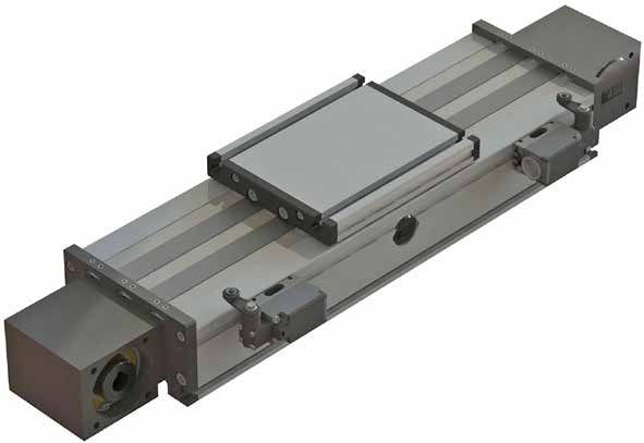
DLZ                                                                                             Installation Instructions
120, 160, 200

1. Safety
1.1 Safety Notes
Bahr Modultechnik GmbH built this state of the art positioning system in accordance with all current safety regulations.
Nevertheless this positioning system may cause hazards to persons or property if it is used inappropriately or not as
intended by the manufacturer or if the safety precautions are not observed.

Proper operation and careful maintenance will ensure high performance and availability of this positioning system.
Any malfunctions or conditions which could affect safety must be eliminated immediately.
Any person involved in the installation, use, operation or maintenance of this positioning system must have read and under-
stood these Installation Instructions.

This includes:
        - understanding the safety precautions mentioned in the text; and
        - making oneself familiar with the configuration of the various operating and usage options and how these work.

This positioning system may be used, installed and operated by qualified personnel only. Any work on and with the
positioning system must be carried out in accordance with the current instructions. For that reason, the instructions must be
kept in a safe place near the positioning system so that it is always at hand. Any general, national or plant-specific safety
regulations must be observed.

The responsibilities regarding the use, installation and operation of this positioning system must be unambiguously defined
and complied with so that there will be no unclear competencies with regard to safety aspects. Before each start-up the user
has to make sure that there are no persons or objects within the danger zone of the positioning system. The linear unit may
only be used if it is in perfect working condition. Any change in condition must be reported to the next responsible person
immediately.

                                                                                                                     22.01.2021

                                                                                                                        Page | 2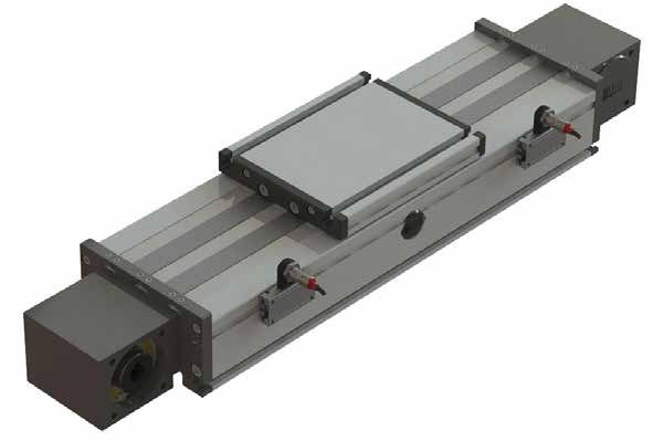
DLZ                                                                                         Installation Instructions
120, 160, 200

1. Safety
1.2 Special Safety Precautions
     - Any work with the positioning system must be carried out in compliance with the current instructions.

     - The system may be opened by authorized skilled personnel only. In case of a defect we recommend contacting
       the manufacturer or returning this positioning system for repair.

     - Connecting the positioning system to an electric power system may be carried out by qualifi ed personnel only;
       any local connection conditions and regulations (e. g. DIN, VDE) must be observed in this respect.

     - The appropriate personal protection equipment (PPE) must be worn during all work.

     - Unauthorized modifi cations of the positioning system are prohibited due to safety reasons.

     - In case of a diagonal or vertical mounting position of the positioning system, the carriage must always be secured
       against fall down (e. g. during mounting, dismantling, maintenance and repair work).

     - The transverse forces, torques and speeds determined by Bahr Modultechnik GmbH for this positioning system
       must not be exceeded.

     - Following an impact, the toothed belt, the ball rail guide and the runner block must be exchanged - even if there
       are no visible damages. For information regarding spare parts please see the spare parts list for the
       corresponding type of positioning system.

     - The rating plate must always be maintained in a legible condition. The data must be easily retrievable at any time.

     - Danger zones are marked by danger symbols for your safety (see 1.3.1).

     - Safety-relevant devices must be inspected with regard to their function, integrity and completeness at regular
       intervals, at least once a year.

                                                                                                                  22.01.2021

                                                                                                                        Page | 3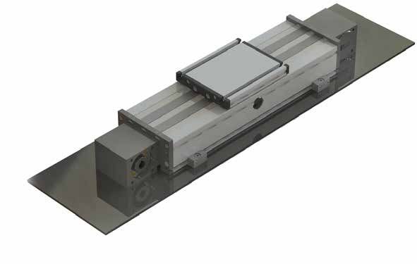
DLZ                                                                                           Installation Instructions
120, 160, 200

1. Safety
1.3 Safety Signs
These warning signs are safety signs warning the user against risks and dangers. Information in these
Installation Instructions regarding particular hazards or dangerous situations in connection with this
positioning system must be observed; non-compliance will lead to increased accident risks.

                                 This „General Warning Sign“ reminds you to be careful. Sections in these Installation
                                 Instructions marked by this sign should be read and observed carefully.
                                 They contain important notes on functions, settings and procedures. Non-compliance
                                 may lead to injuries, malfunction of the positioning system or damage to surrounding
                                 equipment.

                                 The „Entanglement Hazard“ sign warns of hazards due to potentially
                                 moving components. Keep hands, loose clothing and long hair away from moving parts.

                                 The „Hand Injury“ sign warns against hand injuries.
                                 Hands or fi ngers can be crushed, pulled in or otherwise injured.

                                 The „Cutting Hazard“ sign warns of sharp edges that can lead to hand injuries.

1.3.1 General hazard areas on the positioning system

                                                                                                                  22.01.2021

                                                                                                                     Page | 4
DLZ Installation Instructions
120, 160, 200
2. General Notes
2.1 Notes on these Installation Instructions
These Installation Instructions only apply to the positioning system described here and are intended to be used as
documentation by the manufacturer of the final product into which this incomplete machine will be incorporated.
We explicitly point to the fact that the manufacturer of the final product has to prepare operating instructions for the end
user which contain all functions and safety notes with regard to the final product.
This also applies if the positioning system is integrated into a machine. In such case, the machine manufacturer is
responsible for the corresponding safety devices, inspections and for monitoring crushing or shearing points, if any,
as well as for the documentation.
These Installation Instructions will help you to
- avoid hazards,
- avoid downtimes, and
- to ensure or increase the life cycle of this product.
The warnings and safety precautions as well as other requirements mentioned in these Installation Instructions must be met
without exception.
Every person working with the product must read and observe these Installation Instructions.
The product may not be taken into operation unless it complies with the provisions of EC Directive 2006/42/EC
(Machinery Directive). The CE Marking directives must be complied with before marketing the product; this also applies
to the documentation.
We explicitly point to the fact that the secondary manufacturer who will integrate this incomplete machine/partial machine/
machine part into a final product is obliged to extend and complete this documentation correspondingly. In particular, if
electrical components and/or drives are integrated into the product, the secondary manufacturer has to set up a declaration
of conformity. Our Declaration of Incorporation will then automatically become invalid.
22.01.2021
Page | 5DLZ Installation Instructions
120, 160, 200
3. Declaration of Incorporation
3.1 Declaration of Incorporation
as defi ned by EC Machinery Directive 2006/42/EC, Appendix II, 1. B for incomplete machines.
The manufacturer
Bahr Modultechnik GmbH
Nord-Süd-Str. 10a
31711 Luhden - Germany
hereby confirms that the product:
Name: see marking on the system
SN/ID-No: see marking on the system
.:
No y
Id man
60 Ge r
Z 1 in
DL ade
M
complies with the requirements regarding an incomplete machine according to EC Machinery Directive 2006/42/EC.
The following basic requirements of the Machinery Directive 2006/42/EC, Appendix I, have been applied and are
complied with: 1.1.5.; 1.3.2.; 1.3.4.; 6.1.1.
The following harmonizing standards have been applied (as applicable on the date of signature):
DIN EN ISO 12100 – 1 Safety of Machinery – Basic concepts, general principles for design
Part 1: Basic terminology, methodology
DIN EN ISO 12100 – 2 Safety of Machinery – Basic concepts, general principles for design
Part 2: Technical principles and specifications
Bahr Modultechnik GmbH undertakes to submit the technical documentation relating to the incomplete machine according
to Appendix VII B of the Directive 2006/42/EC to the relevant national authorities upon justified request
(in hard copy form).
Luhden / 13.06.2012 Technical documentation
Location, date Jennifer Martitz
This incomplete machine must not be put into operation until the machinery into which it is incorporated has been declared
to be in conformity with the EC Machinery Directive 2006/42/EC.
Luhden, 13.06.2012 Construction manager - Dirk Bahr
Location, date
22.01.2021
Page | 6DLZ Installation Instructions
120, 160, 200
4. Product Information
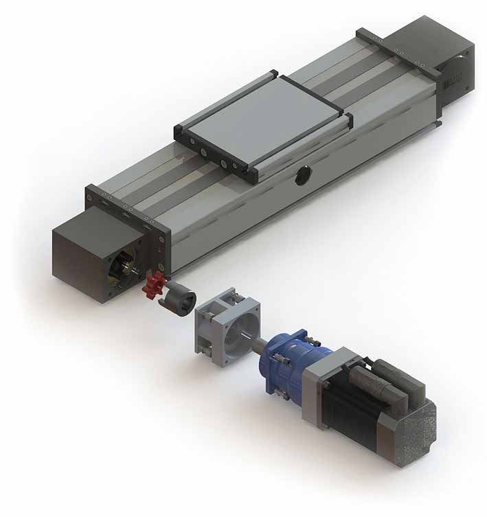
4.1 Working Principle
This unit consists of a rectangular aluminium profile with 2 integrated roller guides. The carriage is moved by a belt drive.
Each standard pulley has got one coupling claw on one side. Belt tension can be readjusted by a simple screw adjustment
device in the carriage. This device can also be used for symmetrical adjustment of two or more linear units running parallel.
The openings of the guide body are sealed with 3 stainless steel cover bands to protect the guide from splash water and dust.
Alternatively, the opening can also be covered with a bellow or can be delivered without cover bands.
4.2 Designs/Basic Lengths
This positioning system is available in the designs and guidance versions indicated in this documentation.
- Upon receipt of the positioning system, please check the system for any potential damages or missing components.
- Notify Bahr Modultechnik GmbH of any defects immediately.
The linear units are manufactured with individual lengths according to your specifi cations. The width and height of the line-
ar unit result from the selected size and design and can be looked up in the Bahr Modultechnik Catalogue.
Get personally or by downloading www.bahr-modultechnik.de
22.01.2021
Page | 7DLZ Installation Instructions
120, 160, 200
4. Product Information
4.3 Forces and torques
Size 120 160 200
Forces and torques
Forces/Torques static dynamic static dynamic static dynamic.
Fx (N) 894 800 1900 1800 4000 3800
Fz Fy (N) 1100 900 3000 2000 4400 3100
Mz Fz (N) 1250 1000 3500 2800 4900 4400
Mx (Nm) 150 125 400 320 600 510
Mx My (Nm) 140 120 360 300 560 480
Fx
Mz (Nm) 100 90 180 150 310 275
Fy All forces and torques related to the following:
My existing values Fy Fz Mx My Mz
+ + + + ≤1
table values Fydyn Fzdyn Mxdyn Mydyn Mzdyn
No-load torque
Nm without cover bands 1,2 1,5 1,8
Nm with cover bands 1,6 2,1 4
Speed
(m/s) max 4 6 8
Tensile force
permanent (N) 900 1900 4000
0,2 s (N) 1000 2090 4300
Geometrical moments of inertia of aluminium profile
lx mm4 6,6x10⁵ 22,2x10⁵ 63,8x10⁵
ly mm4 38,6x10⁵ 122,0x10⁵ 335x105
Elastic modulus N/mm² 70000 70000 70000
For life-time calculation of rollers use our homepage.
Driving torque: Deflection:
F P S
Ma= * * i +Mn F = force (N) f = F*L3
2000*π P = pulley action perimeter (mm) E*I*192
Ma*n Si = safety factor 1,2 ... 2 f = deflection (mm)
Pa = Mn = no-load torque (Nm) F= load (N)
9550 n = rpm pulley (min-1) L= free length (mm)
Ma = driving torque (Nm) E= elastic modulus 70000 (N/mm²)
Pa = motor power (KW) I = second moment of area (mm4)
22.01.2021
Page | 8DLZ Installation Instructions
120, 160, 200
5. Use/Operating Personnel
5.1 Intended Use
The positioning system may be used only for linear moving and positioning of workpieces, assemblies,
measuring devices or similar tasks of comparable nature in industrial plants.
The linear unit must not be used in explosive atmospheres or in direct contact with foodstuffs,
pharmaceutical or cosmetic products.
Catalogue information, the contents of these Installation Instructions and conditions stipulated in the order documents must
be observed. The load data indicated in these Installation Instructions are maximum values which must not be exceeded.
Overloads in any other areas must be avoided as well.
5.2 Improper Use
„Improper use“ is any use not in compliance with the requirements mentionend in chapter 5.1 Intended Use.
In the event of improper use, inappropriate treatment or if this positioning system is used, installed or handled by unskilled
personnel, this linear unit may cause hazards for the staff.
If this positioning system is used improperly, Bahr Modulttechnik GmbH accepts no liability and the general operating permit
will become null and void.
5.2.1 Cases of Frequent Misuse
- Use in explosive atmospheres (if used in explosive areas, sparks can lead to deflagrations, fire or explosions)
- Use of the linear unit with tolerance exceeded
- Insufficient securing of the positioning system
- Insufficient securing of the loads to be moved
- Loads exceeding the indicated limits
- Use in the food industry with direct contact with unpacked foodstuffs
- Use outdoors
- Use in an environment with high humidity > dew point
- Use in heavily contaminated environments
- Use in extremely dusty atmospheres
- Use in atmospheres containing solvents
- Moving animals
- Use in liquids
- Use in temperatures below -10°C and above 60°C
5.3 Who may Use, Install and Operate this Linear Unit
Any authorized persons who have read and understood these Installation Instructions completely are allowed to use,
install and operate this positioning system. The responsibilities for handling this positioning system must be clearly
defined and adhered to.
22.01.2021
Page | 9DLZ Installation Instructions
120, 160, 200
6. Life Stages
6.1 Transport and Storage
When transporting the linear units, you must ensure that a crane, lifting truck or even persons do not grip the unit at the
end elements. The load must be sufficiently secured during transport and the centre of gravity must be observed in order to
prevent the load from tilting.
- Never stand or walk under the load. Respective P.P.E.( Personal Protective Equipment)
must be worn during all measures.
- Accident prevention regulations and safety precautions must be observed.
- During transport and storage, impacts or hits on the shaft ends or driving journals must be avoided.
Any damages due to transport or storage must be reported to the responsible person and Bahr Modultechnik GmbH imme-
diately. The product must be checked for any visible and functional defects by qualified personnel. The start-up of damaged
linear units is prohibited.
The following environmental conditions are prescribed for storing the linear unit:
- no oil contaminated air
- contact with solvent-based lacquers must be prevented
- lowest/highest ambient temperature: 0°C/+60°C
- humidity during storage: storage below dew point is inadmissible
- Supporting the complete surface of the profile body or an appropriate number of support points along the length
of the guide profile will prevent the linear unit from deforming.
Any environmental conditions deviating from the requirements described above will have to be approved
by Bahr Modultechnik GmbH.
22.01.2021
Page | 10DLZ Installation Instructions
120, 160, 200
6. Life Stages
6.2. General
- Before installation, the corrosion protection at the shaft ends of the driven linear units must be removed.
- Cleaning agents must be prevented from entering the bearings.
- When installing transmission elements such as couplings or motor adapters, impacts or hits on the shaft ends and
driving journals must be avoided in order to prevent the bearing from being damaged or becoming unbalanced.
- The linear unit must be secured on a level surface with a planarity of 0.20 mm/m.
- The linear unit must not be warped during installation.
- When the system is to be operated, sufficient fixing points must be selected between and linear unit and
the mounting surface.
- The loads to be moved by the linear unit must be secured properly and sufficiently for the corresponding
application.
- The high dead weight of the component parts and the linear unit presents hazard for people and property.
- When mounting a motor on the linear unit, ensure that the motor shaft and the drive shaft of the linear unit
are axially aligned.
22.01.2021
Page | 11DLZ Installation Instructions
120, 160, 200
6. Life Stages
6.2.1 Locking Torques
Locking torque guidance values for metric cylinder head screws ISO 4762 with 90% utilisation of the 0.2% yield strength,
for a friction coefficient of 0,14.
Dimensions Strength 8.8 Strength 10.9 Strength 12.9
Locking torques MA (Nm) Locking torques MA (Nm) Locking torques MA (Nm)
M4 3,0 4,4 5,1
M5 5,9 8,7 10
M6 10 15 18
M8 25 36 43
M10 49 72 84
Please read the installation instructions for the accessories to obtain information regarding your specific application.
6.2.2 Installation with Fasteners
The specific locking torques of the screws used for installation must always be observed. Please pay attention to the steel
grade of the screws and any special information provided with the accessories. The safety and useful life of the linear axis
are only guaranteed if all these conditions are met. The values can be taken from the table in these Installation Instructions.
2-piece mounting block sets
Mounting block
Code-Nr. Type
03001 DLZ 120
03002 DLZ 160
03003 DLZ 200
22.01.2021
Page | 12DLZ Installation Instructions
120, 160, 200
6. Life Stages
6.2.3 Installation of optional accessories
Mechanical or inductive limit switches
For details regarding the technical characteristics of the limit switches please see the catalogue. Ensure that the cable is laid
in a safe way. Avoid damages to the cable e. g. due to small radiuses; this may lead to failure of the system. The cable must
not enter the travelling path of the linear unit.
Mechanical limit switch
The switch is installed by means of a limit or proximity switch bracket which is mounted onto the guide profile.
The limit and proximity switch brackets can be moved along the guide profile and fixed in the desired position.
Inductive limit switches
The assembly of the proximity switch is a limit and proximity switch bracket that is mounted on the guide profile.
The final and proximity switch brackets are moved and fixed to the guide profile.
22.01.2021
Page | 13DLZ Installation Instructions
120, 160, 200
6. Life Stages
6.2.4 Coupling/Motor Adapter/Motor
The motor can be installed on the pulley with or without gears.
To ensure that this positioning system does not cause a risk, the drive must be designed correctly.
The design and manufacture of the motor adapter must ensure that no axial, radial or angular misalignment can occur.
The installation of the motor follows a logical sequence.
One coupling half is mounted on the pivot of the positioning system.
The second coupling half is mounted on the drive and pushed through the installed motor adapter on
the positioning system which has been prior equipped with the other coupling half.
22.01.2021
Page | 14DLZ Installation Instructions
120, 160, 200
6. Life Stages
6.2.5 Installation of Coupling and Motor
There are two methods to install the motor, either without gears or with a planetary gear.
The manufacturing tolerance are very low, therefore we recommend buying the adapter directly from Bahr Modultechnik.
Angular misalignments and misalignments with respect to the centre of the adapter can lead to serious damages at the
coupling and the bearings.
Another source of defect is the possibility that the coupling knobs might hit each other. Before installing the motor, the safety
distances of 1 mm must be checked.
Installation of coupling and motor - pivot variant with/without feather key
- Clean the pivot and coupling clamping area using solvent
- If necessary, slightly push the coupling hub apart with the help of a screw driver
- Push the coupling onto the pivot with the whole hub length and tighten with the permitted
torques
- Check the safety distances of the coupling knobs (min. 1 mm).
1,0 mm 1,0 mm
1,0 mm 1,0 mm
- Push the motor into the adapter and fix it
22.01.2021
Page | 15DLZ Installation Instructions
120, 160, 200
6. Life Stages
6.3 Commissioning
Only authorized persons who have read and understood these Installation Instructions completely are allowed to take this
positioning system into operation. When this linear unit is in operation, forces arise which can lead to injuries and property
damages. It is imperative that the safety rules and limits of the linear unit are observed.
6.3.1 Normal Operation
While the linear unit is in operation, check it for correct performance of its function regularly.
During normal operation, look for any visible changes of the incomplete machine.
If defects should arise, shut down the linear unit immediately in order to avoid damage.
According to Machinery Directive 2006/42/EC, the operating instructions of the complete machine
are relevant because this incomplete machine is an element of a complete unit.
6.4 Maintenance/Repair/Cleaning
Before starting any work on the linear unit, any electrical drives must be isolated!
All linear units are provided with the required lubricant quantity in the factory. The maintenance intervals are
dependent on the number of operating hours, the degree of loading and the environmental influences.
Lubricant recommendation: see section 8.2 Lubricants
Lubrication intervals: every 1000 km total travel distance; this applies to normal loads and normal environmental conditions.
2
1
Lubrication is effected by an oiled felt insert. The felt can be re-oiled through lubrication nipples attached laterally
to the ends of the roller packs.
- Dismount cover cap (1)
- Drive the carriage through the service position until you can see the first lubricating nipple (2) in the lubrication hole.
- Re-oiled felt now with an oil gun.
- Move the carriage to the second lubricating nipple and re-oiled here as well.
Oils with a viscosity of approx. 200 mm²/s at T=40°C are recommended. The required regreasing intervals depend on environmental conditions, the
standard recommendation is once per month. To ensure a sufficient lubrication, the minimum stroke must equal the carriage length, so that sufficient
greasing is achieved also in the final positions.
22.01.2021
Page | 16DLZ Installation Instructions
120, 160, 200
6.4 Maintenance/Repair/Cleaning
Changing cover band
DLZ 120, 160, 200 - Drive the carriage to servicing position
- Remove fillister head screws (1) and wiper end plate (2)
7 - Size 160 and 200: Unscrew set screws (3) at both bearing-
block plates (4) and pull the cover band out of the bearing
8 block
5
2 1 6
4
- Size 120: Unscrew set screws and remove them with T-nut
3 - Remove sliders (5) and (6) from both sides of the
carriage (7)
- Pull the cover bands (8) out of the carriage
- Insert the new cover bands into the carriage (7)
- Thread the lateral sliders (6) onto the cover band and insert
it into the carriage with middle slider (5)
- Size 160 and 200: Tighten cover bands on one side of
3 the bearing block with set screws (3), tense cover band (8)
at the other bearing block using pliers and tighten with set
screws (3)
- Size 120: Insert T-nut together with set screw into the
bearing block and tighten cover band with set screw.
Adjusting the rollers size DL 120, 160, 200
- Dismount cover cap (5) from servicing hole
- Fasten eccentric bolt with screw key (1)
- Release screws with hexagon socket screw key (2) until the
eccentric bolt can be turned.
- Adjust the gap dimension (A) between top of the carriage and
A
body ground of guiding profile by turning the eccentric bolts
(3). Turning towards + will increase the dimension A. DL120:
A=79 mm; DL160: A=106 mm; DL 200: A=129 mm
- Turn the eccentric bolts (4) to adjust the carriage free of play
by the touch (without initial tension)
5 1 2
- Ensure that the eccentric bolts are adjusted to the right.
4 4
3 3
22.01.2021
Page | 17DLZ Installation Instructions
120, 160, 200
6.4 Maintenance/Repair/Cleaning
Belt tension adjustment DLZ 120, 160, 200
6 2
1
5
3
4
7
Hub / Stroke Kraft / Force
Baugröße / Size
(mm) (N)
< 2500 20
120
2500 - 6000 10
< 2500 20
160
2500 - 6000 10
< 2500 40
200
2500 - 6000 20
- Push the carriage (1) close to one bearing block (2).
- Remove fillister head screws (3).
- Unscrew set screws (4) for middle cover band (5) at the opposite bearing block.
- Pull cover band out of bearing block and turn it to the side.
- Use springe balance (6) to exert the applicable amount of force (see table) on the center of the belt and measure the sag (f).
- Compare the measured value with the diagram below, and tense or release belt as required by tightening or unscrewing the set
screws (7).
- The set screws (7) must be bonded in place with screw locking device.
- Both screws (7) must be screwed in to exactly the same level. Check with sliding caliper.
22.01.2021
Page | 18DLZ Installation Instructions
120, 160, 200
6.4 Maintenance/Repair/Cleaning
Belt exchange DLZ
12
4
2 7
1
11
6
5 3
8 10
9
14 13
S
15
Changing belt of DL 120, 160, 200
- Unscrew cylindric screws (1) and dismount cover caps (2) on both sides of the carriage.
- Unscrew grub screws (3) on both sides of the unit and pull out the only the middle cover band (4) of the bearing-block plate (5).
- Measure the reach of grub screws „S“ (look at drawing) and make note of this value.
- Unscrew grub crews (6) on both sides of the carriage.
- Pull only the middle sliding blocks (7) out of the carriage.
- Unscrew cylindric screws (8) at the bearing-block plates (5) and dismount them completely with the bearing-blocks (9) at both ends of
the unit.
- Pull out the belt-adjusters (11) completely with the belt out of the carriage (12) and the guiding-profile (10).
- Unscrew the countersunk head screws (13) and dismount the belt-adjuster (11,14).
Reconstruction of the unit in opposed order
- Shorten the new belt to the length of the old one.
- Push the belt with teeth side up to the carriage (10) into the slot of the guiding-profile (15) and push it with the ends through each
bearing-block (8,9).
- Mount the belt-adjusters (11,14) by the countersunk head screws (13) and lock them again with glue.
- Push them again together with the belt into the guiding-profile (10) and then into the carriage (12).
- Mount the bearing-block plates (8) again together with the bearing-blocks (9) at the ends of the unit.
- Mount both belt-adjusters (11,14) with consideration of the reach of the grub-screws „S“ and lock the grub screws (6) with glue.
- Pull the middle cover-band (4) through the carriage.
- Pull in the middle sliding blocks (7) into slot of the carriage.
- Mount the grub screws (3) on one side of the unit and tension the 3 cover-bands from the other side and fix them too by the grub-screws
(3).
22.01.2021
Page | 19DLZ Installation Instructions
120, 160, 200
6. Life Stages
6.5 Decommissioning/Dismantling
Before starting any work on the linear unit,
any electrical drives must be isolated.
On linear units in diagonal or vertical mounting positions, the connecting rod must be secured against falling down when
the drive is dismounted. Any loads and forces acting on the system must be removed. Following an impact, the system must
be returned to the manufacturer, even if there are no visible damages.
For information regarding spare parts please see the spare parts list for the corresponding type of linear unit.
6.6 Disposal and Returns
The linear unit must either be disposed of in an environmentally friendly way according to the applicable directives and
regulations, or returned to the manufacturer.
The manufacturer reserves the right to charge a fee for the disposal of this linear unit.
22.01.2021
Page | 20DLZ Installation Instructions
120, 160, 200
7. Liability/Warranty
7.1 Liability
Bahr Modultechnik GmbH does not accept any liability for damages or impairments which occur as a result of modifications
of the construction of this positioning system by third parties or modifications of protection devices.
Only original spare parts may be used for repairs and maintenance.
Bahr Modultechnik GmbH does not accept liability for spare parts which it has not inspected and approved.
Otherwise the EC Declaration of Incorporation will become null and void.
Safety-relevant devices must be inspected with regard to their function, integrity and completeness at regular intervals,
at least once a year.
We reserve the right to make technical changes to the positioning system and to modify or amend these
Installations Instructions.
Requests to Bahr Modultechnik GmbH regarding the availability of earlier versions or adaptations to the current version of
the positioning system will not be accepted.
If you have any questions, please always quote the information on the rating plate.
Our address:
Bahr Modultechnik GmbH
Nord-Süd-Str. 10a
31711 Luhden - Germany
Tel.: +49 (0) 5722 9933-0
Fax: +49 (0) 5722 9933-70
http://www.bahr-modultechnik.com
7.2 Product Monitoring
Bahr Modultechnik GmbH offers state-of-the-art products compliant with current safety standards.
Please let us know immediately if you experience repeated failures or faults.
7.3 Language of the Installation Instructions
The original version of these Installation Instructions was produced in the offi cal EU-language used by the manufacturer of
this incomplete machine. Translations into other languages are translations of the original version and are subject to the egal
provisions of the Machinery Directive.
7.4 Copyright
Individual reproductions, e. g. copies and printouts, may be made for private use only. The production and distribution of
further reproductions is prohibited unless explicitly approved by Bahr Modultechnik GmbH. The user is personally
responsible for complying with statutory regulations and may be liable for misuse.
The copyright to these Installation Instructions is owned by Bahr Modultechnik GmbH.
22.01.2021
Page | 21DLZ Installation Instructions
120, 160, 200
8. Parts Lists / Exploded Drawings
8.1.1 Parts Lists / Exploded Drawings
Please see the parts lists for the standard naming of the parts as defined by Bahr Modultechnik GmbH as well as the corre-
sponding installation positions on the linear axis. Please always indicate the name, the item No. and the quantity in your
orders. Technical variations are possible and depend on the size and version of the positioning system.
Vers. Name Code-No. Quantity
1 guide body profile
2 cover cap
3 cover band The code number and
quantity depends on the
4 Disk storage unit
unit version.
5 pulley block (complete)
6 carriage Please contact our technical
support with the number of
7 eccentric
the origin order.
8 carriage roller In order to avoid mistakes
9 wiper end plate when purchasing
10 belt adjuster spare parts.
11 guide rod
12 belt
6
9 5
4
7
8
10
11 3
2
1
12
22.01.2021
Page | 22DLZ Installation Instructions
120, 160, 200
8. Parts Lists / Exploded Drawings
8.2 Lubricants
All Bahr Modultechnik GmbH products are delivered EX Works with standard lubrication. Subsequent lubrication intervals
are dependent on hours run, degree of loading and environmental factors
(wide temperature ranges, high humidity, aggressive environment etc.).
The lubricants listed below are used for production and mounting of our linear components. To achieve perfect operation
and a useful, prolonged life, we recommend the following products:
For guide rod and carriage roller
- Paraffin oil
DIN 51502: CLP 220
Temperature range: -30°C to +120°C
Name: Soraja GAM 220
Art.-No.: 09001
22.01.2021
Page | 23You can also read