Operating Instructions - S4 Turbo
←
→
Page content transcription
If your browser does not render page correctly, please read the page content below
Operating Instructions

                         S4 Turbo

  Be sure to read and comply with the operating instructions and safety
  information
  Subject to technical change.

  Fröling Heizkessel- und Behälterbau Ges.m.b.H, Industriestrasse 12, A-4710 Grieskirchen
Tel +43 (0) 7248 606-0 Fax +43 (0) 7248 606-600 info@froeling.com www.froeling.com
Introduction
                                                                                                           I

                                      Dear customer,

                                      Congratulations on choosing a quality product from FRÖLING.

                                      The FRÖLING S4 Turbo is a state-of-the-art design that conforms to all
                                      currently applicable standards and testing guidelines.

                                      Please read and observe the operating instructions and always keep
                                      them close to the boiler for reference. Observing the requirements and
                                      safety information in the instruction manual makes a significant
                                      contribution to safe, appropriate, environmentally friendly and
                                      economical operation of the system.

                                      The continuous development of our products means that there may be
                                      minor differences between the illustrations and other content of the
                                      document. If you discover any errors, please let us know.
                                      Subject to technical change.

Fröling Heizkessel- und Behälterbau Ges.m.b.H, Industriestrasse 12, A-4710 Grieskirchen                  Page 3
Tel +43 (0) 7248 606-0 Fax +43 (0) 7248 606-600 info@froeling.com www.froeling.com                       B0510108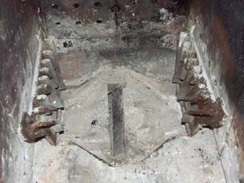
C                                                                                                                      Contents

1 Product Overview                                                                                                                6

2 Safety                                                                                                                          8
     2.1 Safety Information                                                                                                        8
     2.2 Permitted Uses                                                                                                        9
         2.2.1 Permitted fuels................................................................................................. 9
         2.2.2 Non-permitted fuels .......................................................................................... 9
         2.2.3 Who may operate the boiler? ............................................................................. 9
     2.3 Design Information                                                                                                    10
         2.3.1 Approval and obligation to report ...................................................................... 10
         2.3.2 Requirements for central heating water ............................................................. 10
         2.3.3 Ventilation of boiler room ................................................................................ 11
         2.3.4 Installing the heating system / Standards .......................................................... 11
                Return feed lift .............................................................................................. 11
                Combination with storage tank ........................................................................ 12
         2.3.5 Chimney connection / chimney system .............................................................. 12
                Draught limiter.............................................................................................. 12
                Boiler data relating to design of the flue gas system ........................................... 12
     2.4 Safety Devices                                                                                                      13
         2.4.1 Devices for preventing the boiler from overheating.............................................. 13
               Thermal discharge safety device ...................................................................... 13
               Safety Temperature Limiter STL....................................................................... 13
               Safety valve.................................................................................................. 13
     2.5 Safety instructions for the installation room                                                                           13
     2.6 Residual risks                                                                                                          14
     2.7 Emergency procedure                                                                                                      15
         2.7.1 Overheating of the system ............................................................................... 15
         2.7.2 Smell of flue gas ............................................................................................ 15
         2.7.3 Fire .............................................................................................................. 15

3 Operating the system                                                                                                          16
     3.1 Initial startup                                                                                                         16
     3.2 Heating the boiler                                                                                                   17
         3.2.1 Switching on the boiler.................................................................................... 17
         3.2.2 Heating up the boiler ...................................................................................... 17
         3.2.3 Heating up the boiler with automatic ignition ...................................................... 18
         3.2.4 Controlling the boiler ...................................................................................... 18
         3.2.5 Refilling with fuel............................................................................................ 19
               Operating with a storage tank ......................................................................... 19
               Operating without a storage tank ..................................................................... 19

4 Boiler servicing                                                                                                              20
     4.1 General information on servicing                                                                                        20
     4.2 Inspection, cleaning and self maintenance                                                                   21
          4.2.1 Daily maintenance / Each time before heating up ................................................ 21
                Cleaning the heat exchanger pipes ................................................................... 21

Page 4
B0510108                                                                                                                            I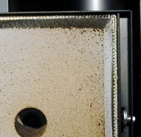
Contents
                                                                                                                           C
                 Checking ignition pipe (only with automatic ignition) ........................................... 21
           4.2.2 Weekly maintenance ....................................................................................... 22
                 Removing ash................................................................................................ 22
                 Checking the thermal discharge safety device .................................................... 22
                 Checking the system pressure ......................................................................... 22
           4.2.3 Monthly maintenance ...................................................................................... 23
                 Cleaning the grating ....................................................................................... 23
                 Cleaning the flue gas sensors........................................................................... 23
           4.2.4 Annual maintenance........................................................................................ 23
                 Checking the primary air openings.................................................................... 23
                 Cleaning the heat exchanger pipes ................................................................... 24
                 Cleaning the carbonisation gas duct.................................................................. 24
                 Checking the seal on the doors ........................................................................ 25
                 Cleaning the flue gas pipe ............................................................................... 25
                 Checking the draught controller flap and explosion flap ....................................... 25
                 Cleaning the induced draught ventilator ............................................................ 26
    4.3 Testing Emissions                                                                                             26
        4.3.1 Measurement at rated load .............................................................................. 26
        4.3.2 Measurement at partial load (if necessary) ......................................................... 26
    4.4 Maintenance agreement / Customer service                                                                            27
    4.5 Replacement parts:                                                                                                  27
    4.6 Disposal information                                                                                               27
        4.6.1 Disposal of the ash ......................................................................................... 27
        4.6.2 Disposal of system components ........................................................................ 27

5 Troubleshooting                                                                                                          28
    5.1 General faults in the power supply                                                                        28
        5.1.1 Behaviour of system after a power failure........................................................... 28
    5.2 Excessive temperature                                                                                               28
    5.3 Faults with fault codes                                                                                       29
        5.3.1 Procedure for fault messages............................................................................ 29
        5.3.2 Acknowledging a fault message ........................................................................ 29

6 Appendix                                                                                                                 30
    6.1 Guarantee conditions                                                                                                30
    6.2 Address of manufacturer                                                                                             30
    6.3 Declaration of Conformity                                                                                           31

Fröling Heizkessel- und Behälterbau Ges.m.b.H, Industriestrasse 12, A-4710 Grieskirchen                                  Page 5
Tel +43 (0) 7248 606-0 Fax +43 (0) 7248 606-600 info@froeling.com www.froeling.com                                       B0510108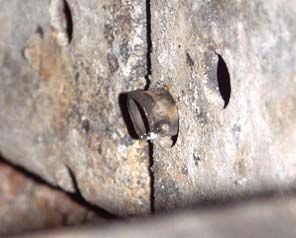
1                                              Product Overview

1 Product Overview

                                       7
                                                          1

                                       2

                 7.1                   3
           7.4
                             7.3

                       7.2                 4

                                       8

                                   9

                  6

                  5

Page 6
B0510108                                                      I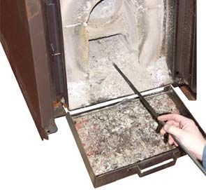
Product Overview
                                                                                                   1

    Item                                                            Description
      1         Insulating door
      2         Fuel loading door
      3         Pre-heating chamber door
      4         Combustion chamber door with inspection glass
      5         Actuators for automatic regulation of primary and secondary air
      6         Lever of the heat exchanger cleaner (WOS system)
      7         Lambdatronic S3200 control system
     7.1        Graphical display to show operating statuses and parameters
     7.2        Status LED (operating status): - green flashing light: boiler active
                                               - flashing red light: warning or fault persists
     7.3        Navigation keys to move around in the menus and to change the parameter values
     7.4        Function keys to call up individual boiler functions directly
                   À For key layout see control unit operating instructions
      8         Service interface
      9         STL - Safety Temperature Limiter

Fröling Heizkessel- und Behälterbau Ges.m.b.H, Industriestrasse 12, A-4710 Grieskirchen          Page 7
Tel +43 (0) 7248 606-0 Fax +43 (0) 7248 606-600 info@froeling.com www.froeling.com               B0510108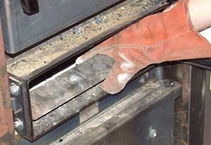
2                                                                                           Safety
                                                                                  Safety Information

2 Safety

  2.1 Safety Information

                                                        DANGER
                     Non-permitted use!

                     Incorrect use of the boiler can cause severe injuries and damage!

                     The instructions and information provided in the manual must be
                     observed.
                     Details on procedure for operation, maintenance and cleaning, as
                     well as troubleshooting for the boiler are included in the
                     individual instructions. Any further work should be carried out by
                     authorised heating engineers or by Fröling customer services.

                                                      WARNING
                     External influences!

                     Negative external influences, such as insufficient combustion air or
                     non-standard fuel can cause serious faults in combustion (e.g.
                     spontaneous combustion of carbonisation gases or flash fires) which
                     can in turn cause serious accidents!

                     Instructions and information for versions and minimum values, as
                     well as norms and guidelines for heating components in the
                     instructions must be observed!

                                                      WARNING
                     Severe injuries and damage can be caused by an inadequate flue gas
                     system!

                     Problems with the flue system, such as poor cleaning of the flue pipe
                     or insufficient chimney draught can cause serious faults in
                     combustion (such as spontaneous combustion of carbonisation gases
                     or flash fires)!

                     You can only be guaranteed of optimum performance from the boiler if the
                     flue gas system is running smoothly!

Page 8
B0510108                                                                                           I
Safety
Permitted Uses                                                                                                         2
 2.2 Permitted Uses
                                      The boiler should only be operated when it is in full working order. It
                                      should be operated in accordance with the instructions, observing safety
                                      precautions, and you should ensure you are aware of the potential
                                      hazards.
                                      Ensure that any faults, which might impair safety, are rectified
                                      immediately.
                                      The Fröling S4 Turbo is intended exclusively for heating up
                                      central heating water. Use only the fuels specified under 2.2.1.
                                      The manufacturer or supplier is not liable for any damages
                                      resulting from non-permitted uses.

            2.2.1     Permitted fuels

                                      For Austria:
                                      Firewood with a max. length of 55cm (w < 25%)

                                      For Germany:
                                      Fuel class 4 (§3 of the 1st BimSchV i. d. g. F.)

                                      Values in practice:         Hardwood                2 years in dry storage
                                                                  Soft wood               1 year in dry storage
                                                                  Coarse wood chips       1 year in dry storage

                                      À Further information on fuel in the in the assembly instructions,
                                        section 2.3

            2.2.2     Non-permitted fuels

                                      The use of fuels not defined under 2.2.1, and particularly the burning of
                                      refuse, is not permitted.

                                                                                 CAUTION
                                       Non-permitted fuels!

                                       Burning non-permitted fuels increases the cleaning requirements and leads to
                                       a build-up of aggressive sedimentation and condensation, which can lead to
                                       damage to the boiler and also voids the warranty. Using non-standard fuels
                                       can lead to severe faults in combustion.

            2.2.3     Who may operate the boiler?

                                      Only trained operators are permitted to operate the boiler.

                                                                                 CAUTION
                                       No unauthorised access to the boiler room!

                                       Risk of personal injury and damage to property.

                                       It is the responsibility of the operator to ensure that unauthorised persons,
                                       especially children, are kept away from the boiler.

Fröling Heizkessel- und Behälterbau Ges.m.b.H, Industriestrasse 12, A-4710 Grieskirchen                            Page 9
Tel +43 (0) 7248 606-0 Fax +43 (0) 7248 606-600 info@froeling.com www.froeling.com                                 B0510108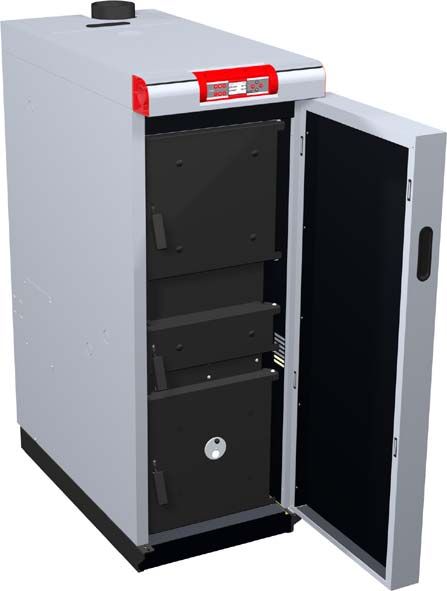
2                                                                                                   Safety
                                                                                         Design Information

  2.3 Design Information
                            It is forbidden to carry out modifications to the boiler or to change or
                            deactivate safety equipment.
                            Always comply with all fire, building, and electrical regulations when
                            installing or operating the boiler system, in addition to following the
                            operating instructions and mandatory regulations that apply in the
                            country in which the boiler is operated.

           2.3.1   Approval and obligation to report

                                                             NOTICE
                              Each heating system must be officially authorised.

                              The appropriate supervisory authority (inspection agency) must always be
                              informed when installing or modifying a heating system, and authorisation
                              obtained from the building authorities.

                              Austria:       Inform the civic/municipal building authorities.
                              Germany:       Register with an approved chimney sweep/the building
                                             authorities.

           2.3.2   Requirements for central heating water

                            The requirements pertaining to the water used to fill the boiler are
                            based on the following standards and guidelines:

                                                                                                     §
                              Applicable standards and guidelines:

                              Austria:       ÖNORM H 5195-1
                              Germany:       VDI 2035
                              Switzerland:   SWKI 97-1

                            There are no other special requirements for central heating water.

                             Note on filling with make-up water: bleed the filling hose before
                              connecting to prevent air from getting into the system.

Page 10
B0510108                                                                                                  I
Safety
Design Information 2
2.3.3 Ventilation of boiler room
The openings for the supply air and the exhaust air should be arranged
as close to opposite each other as possible to achieve a good thermal
draught effect.
The supply air must be drawn in directly from outside. Exhaust air
must be discharged directly outside.
Unless otherwise stipulated by the building regulations applicable to the
room where the boiler is to be installed, the following standard shall
apply:
§
Applicable standard:
- ÖNORM H 5170
2.3.4 Installing the heating system / Standards
The following standards govern the installation of heating systems:
§
Applicable standards:
ÖNORM / DIN EN 12828 Heating Systems in Buildings
The following prior standards still apply:
Austria: - Closed systems as per ÖNORM B 8131
- Open systems as per ÖNORM B 8130
Germany: - Closed systems as per DIN 4751 Part 2
- Open systems as per DIN 4751 Part 1
Return feed lift
If the hot water return feed is below the minimum return feed
temperature, some of the hot water outfeed will be mixed in.
CAUTION
Risk of dropping below dew point/condensation formation if operated
without return feed lift.
Condensation water forms an aggressive condensate when combined
with combustion residue, leading to damage to the boiler.
Regulations stipulate the use of a return feed lift.
The minimum return feed temperature is 55 °C. We recommend fitting
some kind of control device (e.g. thermometer).
Fröling Heizkessel- und Behälterbau Ges.m.b.H, Industriestrasse 12, A-4710 Grieskirchen Page 11
Tel +43 (0) 7248 606-0 Fax +43 (0) 7248 606-600 info@froeling.com www.froeling.com B05101082 Safety
Design Information
Combination with storage tank
You can find more detailed information about storage tank design in the
boiler assembly instructions.
À See assembly instructions “1.2 Design information”
2.3.5 Chimney connection / chimney system
EN 303-5 specifies that the entire flue gas system must be designed to
prevent, wherever possible, damage caused by seepage, insufficient
feed pressure and condensation.
Please note in this respect that flue gas temperatures lower than 160K
above room temperature can occur in the permitted operating range of
1 the boiler.
The flue gas temperatures (for clean systems) and additional flue gas
values can be found in the technical specification sheets.
À See “Boiler data relating to design of the flue gas system“
Connect to the chimney via the shortest path, preferably with a vertical
gradient of less than 30–45°. Insulate the connecting piece.
The entire flue gas system (chimney and connection) must be calculated
as per ÖNORM/DIN EN 13384-1 or prior standards
ÖNORM M 7515/DIN 4705-1.
Local regulations and other statutory regulations also apply.
The chimney must be authorised by a smoke trap sweeper or
chimney sweep.
Draught limiter
We recommend that a draught limiter is fitted (1)
Install the draught limiter directly under the mouth of the flue line,
as there is always low pressure there.
Boiler data relating to design of the flue gas system
S4 Turbo
Description Unit 15 22 28 34 40 50 60
Flue gas temperature RL 140 160 180 140 170 150 170
°C
PL - 110 130 110 130 100 110
Flue gas mass flow RL 0.011 0.016 0.021 0.025 0.030 0.033 0.041
kg/s
PL - 0.007 0.010 0.012 0.015 0.016 0.020
Minimum feed pressure 0.08 0.08 0.08 0.08 0.08 0.08 0.08
Maximum permissible feed mbar
as per ÖNORM / DIN EN 303-5
pressure
Flue pipe diameter mm 150 150 150 150 150 150 150
RL = Rated Load, PL = Partial Load
Page 12
B0510108 ISafety
Safety Devices 2
2.4 Safety Devices
2.4.1 Devices for preventing the boiler from overheating
Thermal discharge safety device
At around 100 °C a valve opens and sends cold water to the safety
heat-exchanger to reduce the temperature.
Safety Temperature Limiter STL
Switches off the blower fan at the maximum boiler temperature of 105
°C. The pumps continue to run.
Once the temperature falls below approx. 95 °C, the STL can be reset
mechanically:
U Remove the back insulating cover
U Unscrew the cap on the STL
U Unlock the STL by pressing with a screwdriver
Safety valve
Protection against over-heating/ excessive pressure:
When the boiler pressure reaches a maximum of 3 bar, the safety valve
opens and the heating water is released in the form of steam.
2.5 Safety instructions for the installation room
1) Danger of fire due to flammable materials.
No flammable materials should be stored near the boiler.
2) Damage due to impurities in combustion air.
Do not use any hydrogen halides or any cleaning agents containing
chlorine in the room where the boiler is installed.
3) Keep the air suction opening of the boiler free of dust.
4) The room where the boiler is installed must be frost-proof.
Fröling Heizkessel- und Behälterbau Ges.m.b.H, Industriestrasse 12, A-4710 Grieskirchen Page 13
Tel +43 (0) 7248 606-0 Fax +43 (0) 7248 606-600 info@froeling.com www.froeling.com B05101082 Safety
Emergency procedure
2.6 Residual risks
WARNING
Touching hot surfaces!
Hot parts and the flue pipe can cause serious burns!
U It should be standard practice to wear protective gloves
should be worn when working on the boiler.
U Only operate the boiler using the handles provided for this
purpose.
U Insulate the flue pipes or simply avoid touching them during
operation.
WARNING
Opening the combustion chamber door during operation!
This may cause injury, damage and smoke!
Do not open the doors behind the insulating door while the
system is operating!
WARNING
Use of non-permitted fuel!
Non-standard fuels can cause serious faults in combustion (e.g.
spontaneous combustion of carbonisation gases / flash fires) which
can lead to serious accidents!
Only use fuels specified in the chapter on “Permitted Uses” in
these operating instructions.
WARNING
Automatic ignition attempt failed!
Possible damage to the equipment!
Damage to heating system (e.g. by frost) because automatic ignition was set
incorrectly or not carried out.
U Before leaving the boiler check the start time that has been set for
automatic ignition.
U Within an appropriate time ensure that automatic ignition has been carried
out successfully.
Due to the different types of wood, Fröling cannot guarantee successful
automatic ignition.
The manufacturer/supplier is not responsible for resulting damage.
Page 14
B0510108 ISafety
Residual risks 2
2.7 Emergency procedure
2.7.1 Overheating of the system
If the system overheats in spite of the safety devices, proceed as
follows:
Do not interrupt the power supply under any circumstances.
U Keep all the doors on the boiler closed.
U Open all mixer taps, switch on all pumps.
´ Fröling heating circuit control takes over this function in
automatic operation.
U Leave the boiler room and close the door.
U Open any available radiator thermostat valves
If the temperature does not drop, inform the installer or Fröling
customer services:
À Page 30, 6.2 Address of manufacturer
2.7.2 Smell of flue gas
DANGER
Smell of flue gas!
Flue gases can cause fatal poisoning!
U Keep all the doors on the boiler closed.
U Air the room where the boiler is installed
U Close the fire protection door and doors to living areas.
2.7.3 Fire
DANGER
Fire!
In case of fire, there is a risk of burns and explosions!
U Turn off the boiler
U Use a tested fire extinguisher for fire class AB to fight the fire
AB powder
Fröling Heizkessel- und Behälterbau Ges.m.b.H, Industriestrasse 12, A-4710 Grieskirchen Page 15
Tel +43 (0) 7248 606-0 Fax +43 (0) 7248 606-600 info@froeling.com www.froeling.com B0510108Operating the system
3 Initial startup
3 Operating the system
3.1 Initial startup
NOTICE
Optimum efficiency and efficient, low-emission operation can
only be guaranteed if the system is set up by trained
professionals and observing the standard factory settings.
Take the following precautions:
U Initial startup should be carried out with an authorised installer or with
Fröling customer services.
The individual steps for initial startup are explained in the operating
instructions for the controller.
À See the operating instructions for the Lambdatronic S 3200
NOTICE
If condensation escapes during the initial heatup phase, this does not
indicate a fault.
If this occurs, clean up using a cleaning rag.
CAUTION
Heating up the boiler too rapidly on initial startup!
Possible damage to the equipment!
If the output during the heating-up process is too great, the combustion
chamber may be damaged as a result of drying out too rapidly!
Drying fissures, on the other hand, are normal and do not indicate a
malfunction.
For this reason the following applies for the first time you heat up the boiler:
Place 1 piece of wood diagonally (1) across the combustion
chamber
U Load the boiler with a small amount of firewood (max. 10-20% of the fuel
loading chamber)
U Ignite it and allow it to burn up with the central pre-heating chamber door
open
Page 16
B0510108 ILambdatronic P 3100 control system
Menus and parameters 4
3.2 Heating the boiler
3.2.1 Switching on the boiler
U Press this function key (6.4) briefly
´ The heating system is controlled via the control system according
to the selected mode in automatic mode.
6.4
U For other modes press the relevant function key
À Operating instructions for the Lambdatronic S 3200
3.2.2 Heating up the boiler
U Open the insulating door and the fuel loading door
´ The induced draught fan switches on
U Fill the fuel loading chamber in accordance with the output
- first layer of small pieces of wood
- second layer of cardboard
- third layer with more small pieces of wood
- fill the rest with firewood
Definition of small pieces of wood:
Firewood with a maximum length of 10 cm
along the edge to the cut
Use firewood with a length of approximately 50 cm and arrange it
lengthwise
The burn-out opening in the grate must remain free!
U Close the fuel loading door
It is recommended that you do not remove the ash in the
combustion chamber during each heating-up process, to protect the
combustion chamber.
6.3
U Press this navigation key (6.3) briefly
´ The induced draught fan switches off
U Open the pre-heating chamber door and ignite the cardboard
Fröling Heizkessel- und Behälterbau Ges.m.b.H, Industriestrasse 12, A-4710 Grieskirchen Page 17
Tel +43 (0) 7248 606-0 Fax +43 (0) 7248 606-600 info@froeling.com www.froeling.com B05101083 Operating the system
Heating the boiler
U Press this navigation key (6.3) briefly
´ The induced draught fan switches on
6.3
U Leave the pre-heating chamber door open for approximately
5 minutes
´ A bed of embers forms
U Close the pre-heating chamber door and the insulating door
3.2.3 Heating up the boiler with automatic ignition
U Open the insulating door and the fuel loading door
´ The induced draught fan switches on
U Check the combustion chamber for residual embers
Residual embers could ignite wood before the automatic start!
U If necessary clean the combustion chamber fully
À See 4.2 Inspection, cleaning and self maintenance
U Open the ignition pipe (IP) to check for dirt and clean if necessary
U Fill the fuel loading chamber in accordance with the output
- first layer of small pieces of wood
- second layer of cardboard and next to the ignition pipe
IP - third layer with more small pieces of wood
- fill the rest with firewood
Definition of small pieces of wood:
Firewood with a maximum length of 10 cm
along the edge to the cut
Use firewood with a length of approximately 50 cm and arrange it
lengthwise
The burn-out opening in the grate must remain free!
U Close the fuel loading door and insulating door
´ The boiler changes to “preventilation” status. To guarantee a safe
boiler operating status and to rule out possible ignition by
residual embers due to incomplete cleaning of the combustion
chamber, the boiler attempts to reach “Heating” status within a
specified safety time without activating the ignition.
´ After this time has elapsed the boiler remains in “ignition wait”
status until the time specified in the ignition menu for automatic
ignition has been reached.
À See boiler control unit operating instructions
3.2.4 Controlling the boiler
Necessary control steps. Displaying or modifying parameters:
À See the operating instructions for the Lambdatronic P 3200
Page 18
B0510108 ILambdatronic P 3100 control system
Menus and parameters 4
3.2.5 Refilling with fuel
WARNING
Touching hot surfaces behind the insulating door!
Risk of burns from hot surfaces!
By the nature of its operation, the surfaces and operating
elements in the area behind the insulating door get hot! When
working with firewood, there is also a risk of injury from splinters.
U When working on the boiler during operation, particularly
when reloading fuel, it should be standard practice to wear
protective gloves.
U Open the central pre-heating chamber door and check the fuel
If the fuel in the boiler has burned up:
U Open the fuel loading door and top up the fuel
Further information for efficient and environmentally friendly heating:
Operating with a storage tank
The reloading intervals should depend exclusively on the storage tank.
If the temperature of the storage tank above has dropped to a certain
temperature (floor heating: approx. 30-40 °C, radiator heating: approx.
50 °C), reload fuel.
With the Lambdatronic S3200, observe the storage tank loading
status on the display!
The amount of fuel should be measured so as to ensure that the storage
tank is continuously warmed to the maximum storage temperature
(max. 80-90 °C).
The amount to reload also depends on the type of fuel.
Operating without a storage tank
NOTICE
Feed based on output!
Only replenish the fuel if energy is needed!
If too much fuel is loaded, the boiler drops below its minimum output limit
and goes over to “constant burn” mode (blower fan switches off)
The level of efficiency drops in constant burn mode, the emissions
increase and the boiler can tar up (pitch formation!)
Fröling Heizkessel- und Behälterbau Ges.m.b.H, Industriestrasse 12, A-4710 Grieskirchen Page 19
Tel +43 (0) 7248 606-0 Fax +43 (0) 7248 606-600 info@froeling.com www.froeling.com B05101084 Boiler servicing
Inspection, cleaning and maintenance
4 Boiler servicing
4.1 General information on servicing
DANGER
Working on electrical components
Risk of serious injuries from electric shocks
U Work on electrical components should only be carried out by authorised
technicians
WARNING
Carrying out maintenance when the boiler is hot!
Hot parts and the flue pipe can cause serious burns!
U It should be standard practice to wear protective gloves
should be worn when working on the boiler.
U Only operate the boiler using the handles provided for this
purpose.
Before starting any maintenance work:
U Allow the fuel in the boiler to burn off
U Allow the boiler to cool down for at least 1 hour
WARNING
Non-permitted cleaning and maintenance!
Incorrect or insufficient cleaning and maintenance of the boiler can
cause serious faults in combustion (e.g. spontaneous combustion of
carbonisation gases / flash fires) and this can lead to serious
accidents!
Clean the boiler following the instructions. Follow the boiler
operating instructions.
NOTICE
We recommend that you keep a maintenance book in accordance with
ÖNORM M7510 of the Technical Directive for Fire Prevention (TRVB)
Page 20
B0510108 IBoiler servicing
Inspection, cleaning and maintenance 4
4.2 Inspection, cleaning and self maintenance
Regular cleaning of the boiler extends its life and is a basic
requirement for smooth running.
So clean the boiler regularly!
Recommended: When cleaning, use an ash vacuum.
4.2.1 Daily maintenance / Each time before heating up
Cleaning the heat exchanger pipes
U Move the lever of the cleaning
system several times before the
heating-up process (5-10 times up
and down)
Checking ignition pipe (only with automatic ignition)
U Before filling the combustion
chamber, check the ignition pipe
of the automatic ignition for dirt
and clean if necessary
Fröling Heizkessel- und Behälterbau Ges.m.b.H, Industriestrasse 12, A-4710 Grieskirchen Page 21
Tel +43 (0) 7248 606-0 Fax +43 (0) 7248 606-600 info@froeling.com www.froeling.com B05101084 Boiler servicing
Inspection, cleaning and maintenance
4.2.2 Weekly maintenance
Removing ash
U Open the insulating door and pre-
heating chamber door
U Scrape the ash from the fuel
loading chamber into the
combustion chamber.
U Open the combustion chamber
door
U Remove the ash using the rounded
ash shovel
U Feed the ash from the lower
channel of the combustion chamber
forwards into the ash drawer
provided using the furnace tool
U Shovel the ash into container
provided
Fire-proof container with cover!
Checking the thermal discharge safety device
U Check the seal of the discharge
valve
´ The discharge pipe must not
drip
U Exception:
Boiler temperature > approx.
100 °C
If water is dripping from the discharge
pipe:
U Clean the discharge safety device
or have the installer replace it if
necessary
Checking the system pressure
U Check the system pressure on the
pressure gauge
´ The value must be 20% over
the pre-stressed pressure of the
expansion tank
À See the expansion tank's
operating instructions
If the system pressure decreases:
U Reload with water
If this happens frequently,
check the seal of the heating
system!
If large pressure fluctuations are
observed:
U Have the expansion tank checked.
Page 22
B0510108 IBoiler servicing
Inspection, cleaning and maintenance 4
4.2.3 Monthly maintenance
Cleaning the grating
U Open the insulating door and
fuel loading chamber door
U Remove the two-part grating
U Remove the ash deposits under
the grating to ensure problem-
free intake of secondary air!
Tip: Use an ash vacuum!
Cleaning the flue gas sensors
1
U Release the retaining screw and remove the flue gas sensor (1)
from the flue gas pipe
U Wipe off the flue gas sensor with a clean cloth
U Push in the flue gas sensor until about 20 mm of the sensor
remains protruding from the bushing
4.2.4 Annual maintenance
Checking the primary air openings
U Open the insulating door and fuel
loading chamber door
I
U Unhinge the cladding plates
U Check the primary air openings (C)
for unobstructed air-flow
U If necessary, clean the openings
U Unhinge the front air guide plate
and clean the slits
For cleaning use the door adjusting
spanner provided if appropriate
Fröling Heizkessel- und Behälterbau Ges.m.b.H, Industriestrasse 12, A-4710 Grieskirchen Page 23
Tel +43 (0) 7248 606-0 Fax +43 (0) 7248 606-600 info@froeling.com www.froeling.com B05101084 Boiler servicing
Inspection, cleaning and maintenance
Cleaning the heat exchanger pipes
U Remove the upper insulating cover
and the cleaning access cover
U Dismantle the fixing bolts (2) and
remove the WOS lever
U Take out the turbulators upwards
together with the mounting bracket
2
U Remove the ash build-up in the
pipes using the cleaning brush
The cleaning brush must be
pushed all the way through
before pulling it up.
The bristles cannot be turned in
the pipe.
U Feed the ash from the lower
channel of the combustion chamber
forwards into the ash drawer
provided using the furnace tool
U Feed the turbulators into the heat
exchanger pipes
U Insert the WOS lever and fix with
screws
U Fit the cleaning cover and top
insulating cover
Cleaning the carbonisation gas duct
U Open the insulating door and fuel
loading chamber door
U Clean the carbonisation gas duct
with a small brush
Carbonisation gases are sucked
out when the insulating door is
opened!
Page 24
B0510108 IBoiler servicing
Inspection, cleaning and maintenance 4
Checking the seal on the doors
U Close the respective door and
check its seal
U Check seal (D) for perfect
alignment on the door frame
´ Imprint in the seal
D
If the seal is coloured black at several
points or the imprint is disjointed:
´ The seal is no longer efficient.
´ Tighten the door latches or
replace the seal
Positioning the doors:
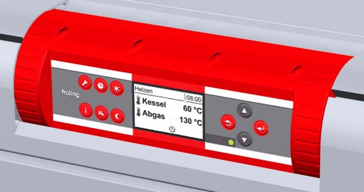
1
U Loosen the locknuts (1) of the locking cam
U Press the door onto the door frame and set the contact pressure
using the locking cam
The adjusting spanner is included in delivery.
U Fix the position by tightening the locknuts
U Set the contact pressure on the door handle side by moving the
locking plate
Cleaning the flue gas pipe
U Clean the pipe connecting the boiler and the chimney with a
chimney sweeping brush
Depending on the layout of the flue pipes and the chimney
draught cleaning yearly may not be enough!
Checking the draught controller flap and explosion flap
U Check the draught controller flap and explosion flap for ease of
operation
Fröling Heizkessel- und Behälterbau Ges.m.b.H, Industriestrasse 12, A-4710 Grieskirchen Page 25
Tel +43 (0) 7248 606-0 Fax +43 (0) 7248 606-600 info@froeling.com www.froeling.com B05101084 Boiler servicing
Inspection, cleaning and maintenance
Cleaning the induced draught ventilator
U Detach the induced draught
ventilator on the back of the boiler
U Check for dirt and damage
U Clean the blower wheel inside and
out using a soft brush or paint
brush
Do not move the balancing
weights on the blower wheel!
U Remove dirt and deposits from the
induced draught housing using a
scraper
U Remove any fallen ash using an
ash vacuum
4.3 Testing Emissions
4.3.1 Measurement at rated load
U Press this key
´ The boiler is operated for 30 min at rated load:
- Boiler temperature setpoint is set to 85°C
- Heating pumps switch on and the mixer valves open
- Boiler loading is activated
When is it possible to measure:
Flue gas temperature at approx. 170°C
CO2 content of the flue gas between 10 and 14%
Boiler temperature above 65°C
4.3.2 Measurement at partial load (if necessary)
After measurement, at rated load in chimney-sweep mode:
U Press this key
´ Automatic operation is activated
U For heat consumption ensure:
- Ensure that heating pumps are switched on
- Open mixer valves and radiator valves
- Set the boiler loading time to the current time
U Force partial load:
- Reduce the boiler temperature setpoint by 5 - 10°C
When is it possible to measure:
Flue gas temperature at approx. 140°C
CO2 content of the flue gas between 10 and 14%
Boiler temperature above 65°C
After measurement all adjusted parameters (e.g. boiler loading times,
..) must be reset to their original value!
Page 26
B0510108 IBoiler servicing
Inspection, cleaning and maintenance 4
4.4 Maintenance agreement / Customer service
We recommend a yearly inspection by Fröling customer services or
an authorised partner (third party maintenance)!
Regular maintenance and servicing by a heating specialist will ensure a
long, trouble-free service life for your heating system.
It will ensure that your system stays environmentally-friendly and
operates efficiently and cost-effectively.
In the course of this maintenance the entire system is inspected and
optimised, particularly regulation and control of the boiler. The emission
measurement carried out can also be used to draw conclusions about
the combustion performance of the boiler.
For this reason, FRÖLING offers a service agreement, which optimises
operating safety. Please see the details in the accompanying guarantee
certificate.
Your Fröling customer service office is also glad to provide consultation.
4.5 Replacement parts:
With Fröling original replacement parts in your boiler, you are using
parts, which are perfectly matched to each other. As the parts fit
together so well, installation times are shortened and lifespan is
maintained.
NOTICE
Installing non-original parts voids the guarantee!
U Only replace components or parts with original replacement parts
4.6 Disposal information
4.6.1 Disposal of the ash
The ash should be disposed of in accordance with waste
management law (AWG).
4.6.2 Disposal of system components
U Ensure that they are disposed of in an environmentally friendly way
in accordance with waste management law
U You can separate and clean recyclable materials and send them to a
recycling centre.
Fröling Heizkessel- und Behälterbau Ges.m.b.H, Industriestrasse 12, A-4710 Grieskirchen Page 27
Tel +43 (0) 7248 606-0 Fax +43 (0) 7248 606-600 info@froeling.com www.froeling.com B05101085 Troubleshooting
5 Troubleshooting
5.1 General faults in the power supply
Error Cause of error Error correction
Nothing is shown on the General power failure
display FI circuit breaker or line Switch on the FI circuit breaker or line
No power to the controls protection is switched off protection
Faulty fuse in the controls Replace fuse – note the current (10AT)
5.1.1 Behaviour of system after a power failure
When the power supply has been restored the boiler returns to the
previously specified mode and is controlled according to the specified
program.
Keep the doors of the boiler closed during and after the power
failure!
5.2 Excessive temperature
The safety temperature limiter (STL) switches off the blower fan at the
maximum boiler temperature of 105 °C. The pumps continue to run.
Once the temperature falls below approx. 95 °C, the STL can be reset
mechanically:
U Remove the back insulating cover
U Unscrew the cap on the STL
U Unlock the STL by pressing with a screwdriver
Page 28
B0510108 ITroubleshooting
5
5.3 Faults with fault codes
2
1
If a fault has occurred and has not yet been cleared:
´ Status LED (1) flashes red
´ A fault message is shown on the display (2)
5.3.1 Procedure for fault messages
The procedure for a fault message as well as causes for faults and
procedure for troubleshooting are described in the operating instructions
of the boiler controls:
À See the operating instructions for the Lambdatronic S 3200
5.3.2 Acknowledging a fault message
Trace and remove the fault and then:
U Press this key
´ Status LED flashes green
Fröling Heizkessel- und Behälterbau Ges.m.b.H, Industriestrasse 12, A-4710 Grieskirchen Page 29
Tel +43 (0) 7248 606-0 Fax +43 (0) 7248 606-600 info@froeling.com www.froeling.com B05101086 Appendix
Manufacturer information
6 Appendix
6.1 Guarantee conditions
Our sale and delivery conditions shall always apply. These are made
available to customers in advance, and are deemed to have been
accepted at the time the contract is concluded.
The warranty conditions can also be found in the enclosed guarantee
certificate.
6.2 Address of manufacturer
FRÖLING
Heizkessel- und Behälterbau GesmbH
Industriestraße 12
A-4710 Grieskirchen
AUSTRIA
TEL +43 (0)7248 606 0
FAX +43 (0)7248 606 600
E-MAIL info@froeling.com
INTERNET www.froeling.com
Page 30
B0510108 IAppendix
Declaration of Conformity 6
6.3 Declaration of Conformity
EU DECLARATION OF CONFORMITY
Product: Firewood boiler
Types: S4 Turbo 15, S4 Turbo 22, S4 Turbo 28, S4 Turbo 34, S4 Turbo 40,
S4 Turbo 50, S4 Turbo 60
EU Directives:
89/392/EEC Legal Regulations for Machinery
73/23/EEC Legal Regulations for Electrical Equipment: Low Voltage
Directive
89/336/EEC Electromagnetic Compatibility (EMC) Directive
97/23/EC Pressure equipment directive in accordance with
Appendix 1
Applied harmonised standards:
ÖNORM – EN 303-5 Boilers for Solid Fuels up to 300 kW
Requirements, Testing and Designation
ÖNORM – EN ISO 3834-2 Welding Quality Specifications
We hereby certify that the serially produced versions of the above products comply with
the directives, guidelines and standards specified.
Grieskirchen; 15/01/2007
Quality assurance Technical services
Fröling Heizkessel- und Behälterbau Ges.m.b.H, Industriestrasse 12, A-4710 Grieskirchen Page 31
Tel +43 (0) 7248 606-0 Fax +43 (0) 7248 606-600 info@froeling.com www.froeling.com B0510108You can also read