Hybrid Inverter User Manual - SUN-8K-SG04LP3 SUN-10K-SG04LP3 SUN-12K-SG04LP3 - Deye
←
→
Page content transcription
If your browser does not render page correctly, please read the page content below
R

Hybrid Inverter
SUN-8K-SG04LP3
SUN-10K-SG04LP3
SUN-12K-SG04LP3

User Manual
Contents
1. Safety Introductions         …………………………………………………    01
2. Product instructions         …………………………………………………    01-04
  2.1 Product Overview
  2.2 Product Size
  2.3 Product Features
  2.4 Basic System Architecture
3. Installation        ……………………………………………………………         05-21
  3.1 Parts list
  3.2 Mounting instructions
  3.3 Battery connection
  3.4 Grid connection and backup load connection
  3.5 PV Connection
  3.6 CT Connection
  3.7 Earth Connection(mandatory)
  3.8 WIFI Connection
  3.9 Wiring System for Inverter
  3.10 Wiring diagram
  3.11 phase parallel connection diagram
4. OPERATION ……………………………………………………………                   22
  4.1 Power ON/OFF
  4.2 Operation and Display Panel
5. LCD Display Icons          ……………………………………………………     23-34
  5.1 Main Screen
  5.2 Solar Power Curve
  5.3 Curve Page-Solar & Load & Grid
  5.4 System Setup Menu
  5.5 Basic Setup Menu
  5.6 Battery Setup Menu
  5.7 System Work Mode Setup Menu
  5.8 Grid Setup Menu
  5.9 Generator Port Use Setup Menu
  5.10 Advanced Function Setup Menu
  5.11 Device Info Setup Menu
6. Mode ……………………………………………………………………                     34-36
7. Limitation of Liability        ………………………………………………   36
8. Datasheet ………………………………………………………………                  36-37
9. Appendix I         ……………………………………………………………          38
10. Appendix II ……………………………………………………………                39
11. Appendix III ……………………………………………………………               40
About This Manual
The manual mainly describes the product informa�on, guidelines for installa�on, opera�on and
maintenance. The manual cannot include complete informa�on about the photovoltaic (PV)
system.

How to Use This Manual
Read the manual and other related documents before performing any opera�on on the inverter.
Documents must be stored carefully and be available at all �mes.
Contents may be periodically updated or revised due to product development. The informa�on
in this manual is subject to change without no�ce. The latest manual can be acquired via
service@deye.com.cn

1. Safety Introduc�ons
· This chapter contains important safety and opera�ng instruc�ons. Read and keep this manual
  for future reference.
· Before using the inverter, please read the instruc�ons and warning signs of the ba�ery and
  corresponding sec�ons in the instruc�on manual.
· Do not disassemble the inverter. If you need maintenance or repair, take it to a professional
  service center.
· Improper reassembly may result in electric shock or fire.
· To reduce risk of electric shock, disconnect all wires before a�emp�ng any maintenance or
  cleaning. Turning off the unit will not reduce this risk.
· Cau�on: Only qualified personnel can install this device with ba�ery.
· Never charge a frozen ba�ery.
· For op�mum opera�on of this inverter, please follow required specifica�on to select appropriate
  cable size. It is very important to correctly operate this inverter.
· Be very cau�ous when working with metal tools on or around ba�eries. Dropping a tool may
  cause a spark or short circuit in ba�eries or other electrical parts, even cause an explosion.
· Please strictly follow installa�on procedure when you want to disconnect AC or DC terminals.
  Please refer to "Installa�on" sec�on of this manual for the details.
· Grounding instruc�ons - this inverter should be connected to a permanent grounded wiring
  system. Be sure to comply with local requirements and regula�on to install this inverter.
· Never cause AC output and DC input short circuited. Do not connect to the mains when DC
  input short circuits.

2. Product Introduc�on
This is a mul�func�onal inverter, combining func�ons of inverter, solar charger and ba�ery
charger to offer uninterrup�ble power support with portable size. Its comprehensive LCD display
offers user configurable and easy accessible bu�on opera�on such as ba�ery charging, AC/solar
charging, and acceptable input voltage based on different applica�ons.

                                           - 01 -
2.1 Product Overview
1
2
3
4 6
5 7
10
11
8
GRID LOAD GEN
9
16
13
14
15
12
1: Inverter indicators 7: Meter-485 port 13: Grid
2: LCD display 8: Ba�ery input connectors 14: Load
3: Func�on bu�ons 9: Func�on port 15: Generator input
4: Power on/off bu�on 10: ModeBUS port 16: WiFi Interface
5: DC switch 11: BMS port
6: Parallel port 12: PV input with two MPPT
- 02 -2.2 Product Size
Inverter Size
Moun�ng bracket
- 03 -2.3 Product Features
- 230V/400V Three phase Pure sine wave inverter.
- Self-consump�on and feed-in to the grid.
- Auto restart while AC is recovering.
- Programmable supply priority for ba�ery or grid.
- Programmable mul�ple opera�on modes: On grid, off grid and UPS.
- Configurable ba�ery charging current/voltage based on applica�ons by LCD se�ng.
- Configurable AC/Solar/Generator Charger priority by LCD se�ng.
- Compa�ble with mains voltage or generator power.
- Overload/over temperature/short circuit protec�on.
- Smart ba�ery charger design for op�mized ba�ery performance
- With limit func�on, prevent excess power overflow to the grid.
- Suppor�ng WIFI monitoring and build-in 2 strings for 1 MPP tracker, 1 string for 1 MPP tracker.
- Smart se�able three stages MPPT charging for op�mized ba�ery performance.
- Time of use func�on.
- Smart Load Func�on.
2.4 Basic System Architecture
The following illustra�on shows basic applica�on of this inverter.
It also includes following devices to have a Complete running system.
- Generator or U�lity
- PV modules
Consult with your system integrator for other possible system architectures depending on your
requirements.
This inverter can power all kinds of appliances in home or office environment, including motor
type appliances such as refrigerator and air condi�oner.
AC cable DC cable
WiFI
GPRS
Cloud services phone
Solar Backup Load On-Grid Home Load Grid
CT
Battery Smart Load Grid-connected Inverter Generator
ATS
- 04 -3. Installa�on
3.1 Parts List
Check the equipment before installa�on. Please make sure nothing is damaged in the package.
You should have received the items in the following package:
Stainless steel an�-collision
Hybrid inverter Wall moun�ng bracket x1 bolt M8×80
x1 x4
Parallel communica�on L-type Hexagon wrench
cable x1 x1 Ba�ery sensor x1
User
Three-Phase Smart Meter
manual SET ESC
User manual x1 Wi-Fi-Plug (op�onal) x1 Meter(op�onal)
x1
Sensor Clamp
x3
- 05 -3.2 Moun�ng instruc�ons
Installa�on Precau�on
This Hybrid inverter is designed for outdoor use(IP65), Please make sure the installa�on site
meets below condi�ons:
· Not in direct sunlight
· Not in areas where highly flammable materials are stored.
· Not in poten�al explosive areas.
· Not in the cool air directly.
· Not near the television Antenna or antenna cable.
· Not higher than al�tude of about 2000 meters above sea level.
· Not in environment of precipita�on or humidity(>95%)
Please AVOID direct sunlight, rain exposure, snow laying up during installa�on and
opera�on. Before connec�ng all wires, please take off the metal cover by removing
screws as shown below:
Considering the following points before selec�ng where to install:
· Please select a ver�cal wall with load-bearing capacity for installa�on, suitable for installa�on
on concrete or other non-flammable surfaces,installa�on is shown below.
· Install this inverter at eye level in order to allow the LCD display to be read at all �mes.
· The ambient temperature should be between -25~60℃ to ensure op�mal opera�on.
· Be sure to keep other objects and surfaces as shown in the diagram to guarantee sufficient
heat dissipa�on and have enough space for removing wires.
- 06 -≥500mm
≥500mm
For proper air circula�on to dissipate heat, allow a clearance of approx. 50cm to the side and
approx. 50cm above and below the unit. And 100cm to the front.
Moun�ng the inverter
Remember that this inverter is heavy! Please be careful when li�ing out from the package.
Choose the recommend drill head(as shown in below pic) to drill 4 holes on the wall,
52-60mm deep.
1. Use a proper hammer to fit the expansion bolt into the holes.
2. Carry the inverter and holding it, make sure the hanger aim at the expansion bolt,fix the
inverter on the wall.
3. Fasten the screw head of the expansion bolt to finish the moun�ng.
Inverter hanging plate installa�on
- 07 -3.3 Ba�ery connec�on
For safe opera�on and compliance, a separate DC over-current protector or disconnect device is
required between the ba�ery and the inverter. In some applica�ons, switching devices may not
be required but over-current protectors are s�ll required. Refer to the typical amperage in the
table below for the required fuse or circuit breaker size.
Model Wire Size Cable(mm 2 ) Torque value(max)
8Kw 1AWG 40 24.5Nm
10Kw 1/0AWG 60 24.5Nm
12Kw 1/0AWG 60 24.5Nm
Chart 3-2 Cable size
- 08 -All wiring must be performed by a professional person.
Connec�ng the ba�ery with a suitable cable is important for safe and efficient
opera�on of the system. To reduce the risk of injury, refer to Chart 3-2 for
recommended cables.
Please follow below steps to implement ba�ery connec�on:
1. Please choose a suitable ba�ery cable with correct connector which can well fit into the
ba�ery terminals.
2. Use a suitable screwdriver to unscrew the bolts and fit the ba�ery connectors in, then
fasten the bolt by the screwdriver, make sure the bolts are �ghtened with torque of
24.5 N.M in clockwise direc�on.
3. Make sure polarity at both the ba�ery and inverter is correctly connected.
For 8-10KW model, ba�ery connector screw size: M10
3. In case of children touch or insects go into the inverter, Please make sure the inverter
connector is fasten to waterproof posi�on by twist it clockwise.
Installa�on must be performed with care.
Before making the final DC connec�on or closing DC breaker/disconnect, be sure
posi�ve(+) must be connect to posi�ve(+) and nega�ve(-) must be connected to
nega�ve(-). Reverse polarity connec�on on ba�ery will damage the inverter.
- 09 -3.3.2 Func�on port defini�on
Inverter
1 2 3 4 5 6 7 8 1 2 3 4 5 6 7 8 Parallel_A Parallel_B Meter-485
ModeBUS BMS
Batt Temp 240V Coil Parallel A: Parallel communica�on
Sensor Neutral port 1 (CAN interface).
Earth
Bond Parallel B: Parallel communica�on
CT -L1 port 2 (CAN interface).
Meter_485: for energy meter
communica�on.
CT -L2
Gen start-up ModeBUS: Reserved.
N/O Relay
BMS: BMS port for ba�ery
CT -L3 communica�on(CAN/RS485).
CN1:
TEMP (1,2): ba�ery temperature sensor for lead
acid ba�ery.
CT-L1 (3,4): current transformer (CT1) for“zero
export to CT”mode clamps on L1 when
in three phase system.
CT-L2 (5,6): current transformer (CT2) for“zero
export to CT”mode clamps on L2 when
in three phase system.
CT-L3 (7,8): current transformer (CT3) for“zero export to CT”mode clamps on L3 when in
three phase system.
CN2:
G-start (1,2): dry contact signal for startup the coil
relay
diesel generator. open
contact
When the "GEN signal" is ac�ve, the open contact
(GS) will switch on (no voltage output).
G-valve (3,4): reserved. G S
Grid_Ry(5,6): 230V output port when inverter is on GS (diesel generator startup signal)
RSD (7,8): provide 12Vdc output when inverter is on.
- 10 -3.3.3 Temperature sensor connec�on for lead-acid ba�ery
12
Temp. CT
- 11 -3.4 Grid connec�on and backup load connec�on
· Before connec�ng to grid, please install a separate AC breaker between inverter and grid. Also,
it is recommended that installs an AC breaker between backup load and inverter.This will ensure
the inverter can be securely disconnected during maintenance and fully protected from over
current.The recommended of AC breaker is 20A for 8kw, 20A for 10kw and 20A for 12KW.
· There are three terminal blocks with "Grid" "Load"and "GEN" markings. Please do not misconnect
input and output connectors.
All wiring must be performed by a qualified personnel.It is very important for
system safety and efficient opera�on to use appropriate cable for AC input
connec�on. To reduce risk of injury, please use the proper recommended cable
as below.
Model Wire Size Cable(mm 2 ) Torque value(max)
8/10/12KW 11AWG 4 1.2Nm
Chart 3-3 Recommended Size for AC wires
Please follow below steps to implement Grid, load and Gen port connec�on:
1. Before making Grid, load and Gen port connec�on, be sure to turn off AC baeaker or
disconnector first.
2. Remove insula�on sleeve 10mm length, unscrew the bolts, insert the wires according to
polari�es indicated on the terminal block and �ghten the terminal screws. Make sure the
connec�on is complete.
PE
T(L3)
S(L2) GRID LOAD GEN PORT
N R(L1)
GRID
PE
T(L3) PE
S(L2) T(L3)
N R(L1) S(L2)
LOAD N R(L1) GEN PORT
- 12 -Be sure that AC power source is disconnected before a�emp�ng to wire it to the
unit.
3. Then, insert AC output wires according to polari�es indicated on the terminal block and �ghten
terminal. Be sure to connect corresponding N wires and PE wires to related terminals as well.
4. Make sure the wires are securely connected.
5. Appliances such as air condi�oner are required at least 2-3 minutes to restart because it is
required to have enough �me to balance refrigerant gas inside of circuit. If a power shortage
occurs and recovers in short �me, it will cause damage to your connected appliances. To
prevent this kind of damage, please check manufacturer of air condi�oner if it is equipped with
�me-delay func�on before installa�on. Otherwise, this inverter will trigger overload fault and
cut off output to protect your appliance but some�mes it s�ll causes internal damage to the air
condi�oner
3.5 PV Connec�on
Before connec�ng to PV modules, please install a separately DC circuit breaker between
inverter and PV modules. It is very important for system safety and efficient opera�on to
use appropriate cable for PV module connec�on. To reduce risk of injury, please use the
proper recommended cable size as below.
Model Wire Size Cable(mm 2 )
8/10/12KW 12AWG 4
Chart 3-4 Cable size
To avoid any malfunc�on, do not connect any PV modules with possible current
leakage to the inverter. For example, grounded PV modules will cause current
leakage to the inverter. When using PV modules, please be sure NO grounding.
It is requested to use PV junc�on box with surge protec�on. Otherwise, it will
cause damage on inverter when lightning occurs on PV modules.
- 13 -3.5.1 PV Module Selec�on:
When selec�ng proper PV modules, please be sure to consider below parameters:
1) Open circuit Voltage (Voc) of PV modules not exceeds max. PV array open circuit voltage of
inverter.
2) Open circuit Voltage (Voc) of PV modules should be higher than min. start voltage.
Inverter Model 8KW 10KW 12KW
PV Input Voltage 550V (150V~800V)
PV Array MPPT Voltage Range 200V-650V
No. of MPP Trackers 2
No. of Strings per MPP Tracker 1+1 2+1 2+1
Chart 3-5
3.5.2 PV Module Wire Connec�on:
1. Switch the Grid Supply Main Switch(AC)OFF.
2. Switch the DC lsolator OFF.
3. Assemble PV input connector to the inverter.
Safety Hint:
Please don’t connect PV array posi�ve or nega�ve pole to the ground, it could
cause serious damages to the inverter.
Safety Hint:
Before connec�on, please make sure the polarity of the output voltage of PV
array matches the “DC+” and “DC-” symbols.
Safety Hint:
Before connec�ng inverter, please make sure the PV array open circuit voltage is
within the 1000V of the inverter.
Pic 3.1 DC+connector (MC4) Pic 3.2 DC-connector (MC4)
- 14 -Safety Hint:
Please use approved DC cable for PV system.
Cross section(mm )
Cable type
Range Recommended value
Industry generic PV cable 4.0~6.0
4.0(12AWG)
(model: PV1-F) (12~10AWG)
Chart 3-6
The steps to assemble the DC connectors are listed as follows:
a) Strip off the DC wire about 7mm, disassemble the connector cap nut (see picture 5.3).
7mm
7mm
Pic 3.3 Disassemble the connector cap nut
b) Crimping metal terminals with crimping pliers as shown in picture 5.4.
Pic 3.4 Crimp the contact pin to the wire
c) Insert the contact pin to the top part of the connector and screw up the cap nut to the top
part of the connector. (as shown in picture 5.5).
- 15 -Pic 3.5 connector with cap nut screwed on
d) Finally insert the DC connector into the posi�ve and nega�ve input of the inverter, shown as
picture 5.6
Pic 3.6 DC input connec�on
Warning:
Sunlight shines on the panel will generate voltage, high voltage in series may
cause danger to life. Therefore, before connec�ng the DC input line, the solar
panel needs to be blocked by the opaque material and the DC switch should
be 'OFF', otherwise, the high voltage of the inverter may lead to life-
threatening condi�ons.
- 16 -3.6 CT Connec�on
N R S T PE N R S T PE N R S T PE
Grid Load GEN
N R S T PE
Inverter
N
White wire Black wire
3 4 5 67 8
R
CT1
S
CT2
T
CT3
N
Grid
- 17 -Note:
When the inverter is in the off-grid state, the N line needs to be connected to the
earth.
3.7 Earth Connec�on(mandatory)
Ground cable shall be connected to ground plate on grid side this prevents electric shock. if the
original protec�ve conductor fails.
3.8 WIFI Connec�on
For the configura�on of Wi-Fi Plug, please refer to illustra�ons of the Wi-Fi Plug.
- 18 -PV This diagram is an example for an applica�on that neutral connects with the
PE in a distribu�on box.
For countries such as Australia, New Zealand, South Africa, etc., please follow
DC Breaker local wiring regula�ons!
BMS
N N
R R
S RCD S
Load
T T
Battery AC Breaker
PE or
DC Breaker
3.9 Wiring System for Inverter
Load
Hybrid Inverter
CT
N N
N
R R
CT1
- 19 -
R S S Grid
GEN S CT2
T T T
CT3
PORT
PE AC Breaker AC Breaker
AC Breaker PE
Grid
PE
N-BAR
RCD
E-N
Link
E-BAR E-BAR
N R S T PE
Home Loads3.10 Wiring diagram
CAN L wire N wire PE wire
Inverter
BMS
N R S T PE N R S T PE N R S T PE
Grid Load GEN
Inverter Ground
①DC
Breaker
②AC
Breaker
Battery pack
③AC Breaker
CT1 CT2 CT3
T
Grid PE N R S T S
④AC Breaker R
N
PE
Home Load
① DC Breaker for battery
Backup Load
SUN 8K-SG: 250A DC breaker
SUN 10K-SG:300A DC breaker
SUN 12K-SG:300A DC breaker
② AC Breaker for grid and backup load
SUN 8K-SG: 80A AC breaker
SUN 10K-SG:80A AC breaker
SUN 12K-SG:80A AC breaker
③ AC Breaker for grid and backup load
SUN 8K-SG: 20A AC breaker
SUN 10K-SG:32A AC breaker
SUN 12K-SG:32A AC breaker
④AC Breaker for home load
Depends on household loads
- 20 -3.11 phase parallel connec�on diagram
CAN L wire N wire PE wire
Inverter N R S T PE N R S T PE N R S T PE
No.3 Grid Load GEN
Parallel_A Parallel_B Meter-485
(slave)
Ground
*Paralleling operation function is developing, and it will be avaiable soon.
Inverter
⑤⑦⑨ AC Breaker for backup load
④⑥⑧ AC Breaker for grid port
N R S T PE N R S T PE N R S T PE
① Inverter
SUN 10K-SG:80A AC breaker
SUN 12K-SG:80A AC breaker
SUN 10K-SG:32A AC breaker
SUN 12K-SG:32A AC breaker
SUN 8K-SG: 80A AC breaker
SUN 8K-SG: 20A AC breaker
Grid Load GEN ④ ⑤
No.2
(slave)
⑦
②
⑥
SUN 10K-SG:300A DC breaker
SUN 12K-SG:300A DC breaker
SUN 8K-SG: 250A DC breaker
①②③ DC Breaker for battery
⑩ AC Breaker for home load
Depends on household loads
Inverter N R S T PE N R S T PE N R S T PE
No.1 Grid Load GEN
(master)
③ ⑨
Battery pack ⑧
CT1 CT2 CT3
T
Grid PE N R S T
⑩
S
R
N
PE
Home Load
Master inverter Slave Inverter Slave Inverter Backup Load
Advanced Function Advanced Function Advanced Function
Parallel Modbus SN A Phase Parallel Modbus SN A Phase Parallel Modbus SN A Phase
Master 01 B Phase Master 02 B Phase Master 03 B Phase
Paral. Paral. Paral.
Slave C Phase Set3 Slave C Phase Set3 Slave C Phase Set3
- 21 -4. OPERATION
4.1 Power ON/OFF
Once the unit has been properly installed and the ba�eries are connected well, simply press
On/Off bu�on(located on the le� side of the case) to turn on the unit. When system without
ba�ery connected, but connect with either PV or grid, and ON/OFF bu�on is switched off, LCD
will s�ll light up(Display will show OFF), In this condi�on, when switch on ON/OFF bu�on and
select NO ba�ery,system can s�ll working.
4.2 Opera�on and Display Panel
The opera�on and display panel, shown in below chart, is on the front panel of the inverter.
It includes four indicators, four func�on keys and a LCD display, indica�ng the opera�ng status
and input/output power informa�on.
LED Indicator Messages
DC Green led solid light PV Connec�on normal
AC Green led solid light Grid Connec�on normal
Normal Green led solid light Inverter opera�ng normal
Alarm Red led solid light Malfunc�on or warning
Chart 4-1 LED indicators
Function Key Description
Esc To exit se�ng mode
Up To go to previous selec�on
Down To go to next selec�on
Enter To confirm the selec�on
Chart 4-2 Func�on Bu�ons
- 22 -5. LCD Display Icons
5.1 Main Screen
The LCD is touchscreen, below screen shows the overall informa�on of the inverter.
05/28/2019 15:34:40
0 8.30 12 0 -3.00 8
KW KW
ON
25%
0 -2.00
KW
8 0 3.00
KW
8
1.The icon in the center of the home screen indicates that the system is Normal opera�on. If it
turns into "comm./F01~F64" , it means the inverter has communica�on errors or other errors,
the error message will display under this icon(F01-F64 errors, detail error info can be viewed in
the System Alarms menu).
2.At the top of the screen is the �me.
3.System Setup Icon, Press this set bu�on,you can enter into the system setup screen which
including Basic Setup, Ba�ery Setup, Grid Setup, System Work Mode, Generator port use,
Advanced func�on and Li-Ba� info.
4.The main screen showing the info including Solar, Grid, Load and Ba�ery. Its also displaying the
energy flow direc�on by arrow. When the power is approximate to high level, the color on the
panels will changing from green to red so system info showing vividly on the main screen.
· PV power and Load power always keep posi�ve.
· Grid power nega�ve means sell to grid, posi�ve means get from grid.
· Ba�ery power nega�ve means charge, posi�ve means discharge.
- 23 -5.1.1 LCD opera�on flow chart
Solar Page Solar Graph
Grid Page Grid Graph
Inverter Page
Main Screen
Battery Page BMS Page
Load Page Load Graph
Battery Setting
System Work Mode
Grid Setting
System Setup
Gen Port Use
Basic Setting
Advanced Function
Device info
- 24 -5.2 Solar Power Curve
Solar This is Solar Panel detail page.
Power: 1560W ① Today=8.0 KWH ③ ① Solar Panel Genera�on.
② Voltage, Current, Power for each MPPT.
PV1-V: 286V PV2-V: 45V
② Total =12.00 KWH
PV1-I: 5.5A PV2-I: 0.0A ③ Solar Panel energy for Day and Total.
PV1-P: 1559W PV2-P: 1W
Energy Press the “Energy “bu�on will enter into the power
curve page.
Inverter This is Inverter detail page.
① Inverter Genera�on.
Power: 44W ① DC-T:52.6C ③ ② Voltage, Current, Power for each Phase.
L1: 230V
L2: 230V
② AC-T:41.0C ③ *DC-T: mean DC-DC temperature,
L3: 230V AC-T: mean Heat-sink temperature.
l1: 0.6A *Note: this part info is not avaiable for some
l2: 0.6A
l3: 0.6A
LCD FW.
Load This is Back-up Load detail page.
Power: 55W ① Today=0.5 KWH ③ ① Back-up Power.
② Voltage, Power for each Phase.
Total =1.60 KWH
③ Back-up consump�on for Day and Total.
L1: 220V P1: 19W
② Press the “Energy “ bu�on will enter into the power
L2: 220V P2: 18W
curve page.
L3: 220V P3: 18W
Energy
Grid This is Grid detail page.
① Status, Power, Frequency.
Stand by ① BUY ③
0W Today=2.2KWH ② L: Voltage for each Phase
Total =11.60 KWH CT: Power detected by the external current
0.0Hz sensors
SELL
LD: Power detected using internal sensors on
CT1: 0W LD1:0W ② Today=0.0KWH AC grid in/out breaker
CT2: 0W LD2:0W Total =8.60 KWH ③ BUY: Energy from Grid to Inverter,
CT3: 0W LD3:0W SELL: Energy from Inverter to grid.
Energy Press the “Energy “ bu�on will enter into the power
L1: 0V L2: 0V L3: 0V curve page.
- 25 -Li-BMS
Mean Voltage:50.34V Charging Voltage :53.2V
Batt Total Current:55.00A Discharging Voltage :47.0V Sum
Mean Temp :23.5C Charging current :50A Data
Discharge Total SOC :38% Discharging current :25A
Dump Energy:57Ah
Details
Data
U:49.58V
I:2.04A
Li-BMS
Power: 101W Volt Curr Temp SOC Energy Charge Fault
Volt Curr
1 50.38V 19.70A 30.6C 52.0% 26.0Ah 0.0V 0.0A 0|0|0
Temp:25.0C
Energy 2
3
4
50.33V
50.30V
0.00V
19.10A
16.90A
0.00A
31.0C
30.2C
0.0C
51.0%
12.0%
0.0%
25.5Ah
6.0Ah
0.0Ah
53.2V
53.2V
0.0V
25.0A
25.0A
0.0A
0|0|0
0|0|0
0|0|0
Sum
Data
5 0.00V 0.00A 0.0C 0.0% 0.0Ah 0.0V 0.0A 0|0|0
6 0.00V 0.00A 0.0C 0.0% 0.0Ah 0.0V 0.0A 0|0|0
7 0.00V 0.00A 0.0C 0.0% 0.0Ah 0.0V 0.0A 0|0|0
8 0.00V 0.00A 0.0C 0.0% 0.0Ah 0.0V 0.0A 0|0|0
This is Ba�ery detail page. 9 0.00V 0.00A 0.0C 0.0% 0.0Ah 0.0V 0.0A 0|0|0
10 0.00V 0.00A 0.0C 0.0% 0.0Ah 0.0V 0.0A 0|0|0 Details
11 0.00V 0.00A 0.0C 0.0% 0.0Ah 0.0V 0.0A 0|0|0 Data
if you use Lithium Ba�ery, you can enter BMS page. 12 0.00V 0.00A 0.0C 0.0% 0.0Ah 0.0V 0.0A 0|0|0
13 0.00V 0.00A 0.0C 0.0% 0.0Ah 0.0V 0.0A 0|0|0
14 0.00V 0.00A 0.0C 0.0% 0.0Ah 0.0V 0.0A 0|0|0
15 0.00V 0.00A 0.0C 0.0% 0.0Ah 0.0V 0.0A 0|0|0
5.3 Curve Page-Solar & Load & Grid
Solar Power Production:Day System Solar Power:Month
3000W 2019-5-28 2000Wh 5-2019
100% 2000
80% 1600
60% 1200
40% 800
20% 400
0
1 3 5 7 9 11 13 15 17 19 21 23 05 10 15 20 25 30
CANCEL Day Month Year Total CANCEL Day Month Year Total
System Solar Power:Year System Grid Power:Total
KWh 2019 2000KWh TOTAL
200 2000
160 1600
120 1200
80 800
40 400
0
1 2 3 4 5 6 7 8 9 10 11 12 20 20 20 20 20 20 20 20 20 20 20 20 20 20 20 20 20
16 18 20 22 24 26 28 30 32 34 36 38 40 42 44 46 48
CANCEL Day Month Year Total CANCEL Day Month Year Total
Solar power curve for daily, monthly, yearly and total can be roughly checked on the LCD, for more
accuracy power genera�on, pls check on the monitoring system. Click the up and down arrow to
check power curve of different period.
- 26 -5.4 System Setup Menu
System Setup
This is System Setup page.
System Work Mode
Battery
Setting Gen Port
Grid Setting Use
Basic Advanced
Setting Function Device Info.
5.5 Basic Setup Menu
Basic Setting
Factory Reset: Reset all parameters of the inverter.
Time Syncs Beep Auto Dim Lock out all changes: Enable this menu for se�ng
Year Month Day Basic parameters that require locking and cannot be set up.
2019 03 17
Set Before performing a successful factory reset and locking
the systems, to keep all changes you need to type in a
Hour Minute password to enable the se�ng.
24-Hour 09 15 The password for factory se�ngs is 9999 and for lock
out is 7777.
Factory Reset Lock out all changes
PassWord
Factory Reset PassWork: 9999
X--X--X--X DEL Lock out all changes PassWork: 7777
1 2 3
4 5 6
7 8 9
CANCEL 0 OK
- 27 -5.6 Ba�ery Setup Menu
Battery Setting
Ba�ery capacity: it tells Deye hybrid inverter to know
Batt Mode your ba�ery bank size.
Lithium Batt Capacity 400Ah
Batt
Use Ba� V: Use Ba�ery Voltage for all the se�ngs (V).
Use Batt V Max A Charge 40A
Mode Use Ba� %: Use Ba�ery SOC for all the se�ngs (%).
Use Batt % Max A Discharge 40A Max. A charge/discharge: Max ba�ery charge/discharge
No Batt
current(0-115A for 5KW model, 0-90A for 3.6KW model).
Activate Battery
For AGM and Flooded, we recommend Ah ba�ery
size x 20%= Charge/Discharge amps.
. For Lithium, we recommend Ah ba�ery size x 50% =
Charge/Discharge amps.
. For Gel, follow manufacturer' s instruc�ons.
No Ba�: �ck this item if no ba�ery is connected to the system.
Ac�ve ba�ery: This feature will help recover a ba�ery that is over discharged by slowly charging from
the solar array or grid.
Battery Setting This is Ba�ery Setup page. ①③
Start 0.0V 0.0V ② Start =30%: Percent S.O.C at 30% system will AutoStart a
connected generator to charge the ba�ery bank.
A
① 40A 40A
Batt
Set2 A = 40A: Charge rate of 40A from the a�ached
Gen Charge Grid Charge generator in Amps.
Gen Signal Grid Signal
Gen Charge: uses the gen input of the system to charge
ba�ery bank from an a�ached generator.
Gen Max Run Time 0.0 hours
③ Gen Signal: Normally open relay that closes when the
Gen Down Time 0.5 hours Gen Start signal state is ac�ve.
Gen Max Run Time: It indicates the longest �me
This is Grid Charge, you need select. ② Generator can run in one day, when �me is up, the
Start =30%: No use,Just for customiza�on. Generator will be turned off. 24H means that it does
A = 40A: It indicates the Current that the not shut down all the �me.
Grid charges the Ba�ery. Gen Down Time: It indicates the delay �me of the
Grid Charge: It indicates that the grid charges Generator to shut down a�er it has reached the running
the ba�ery. �me.
Grid Signal: Disable.
Battery Setting There are 3 stages of charging the Ba�ery . ①
Float V ① 53.6V Shutdown ③ 20%
This is for professional installers, you can keep it
Low Batt 35% if you do not know. ②
Absorption V 57.6V Batt
Restart 50% Set3
Shutdown 20%: The inverter will shutdown if the SOC
Equalization V 57.6V TEMPCO(mV/C/Cell)
below this value.
Equalization Days 30 days
② -5
Low Ba� 35%: The inverter will alarm if the SOC
③
Batt Resistance below this value.
Equalization Hours 3.0 hours
25mOhms Restart 50%: Ba�ery SOC at 50% AC output will resume.
- 28 -Recommended ba�ery se�ngs
Torque value
Battery Type Absorption Stage Float Stage (every 30 days 3hr )
AGM (or PCC) 14.2v (57.6v) 13.4v (53.6v) 14.2v(57.6v)
Gel 14.1v (56.4v) 13.5v (54.0v)
Wet 14.7v (59.0v) 13.7v (55.0v) 14.7v(59.0v)
Lithium Follow its BMS voltage parameters
5.7 System Work Mode Setup Menu
System Work Mode Work Mode
Selling First: This Mode allows hybrid inverter to sell
Selling First 12000 Max Solar Power back any excess power produced by the solar panels to
Zero Export To Load Solar Sell
Work the grid. If �me of use is ac�ve, the ba�ery energy also
Mode1
can be sold into grid.
Zero Export To CT Solar Sell The PV energy will be used to power the load and charge
the ba�ery and then excess energy will flow to grid.
Max Sell Power 12000 Zero-export Power 20
Power source priority for the load is as follows:
Energy pattern BattFirst LoadFirst 1. Solar Panels.
Grid Peak Shaving 8000 Power 2. Grid.
3. Ba�eries (un�l programable % discharge is reached).
Zero Export To Load: Hybrid inverter will only provide power to the backup load connected. The hybrid
inverter will neither provide power to the home load nor sell power to grid. The built-in CT will detect
power flowing back to the grid and will reduce the power of the inverter only to supply the local load and
charge the ba�ery.
Solar Backup Load On-Grid Home Load Grid
Battery
Zero Export To CT: Hybrid inverter will not only provide power to the backup load connected but also give
power to the home load connected. If PV power and ba�ery power is insufficient, it will take grid energy
as supplement. The hybrid inverter will not sell power to grid. In this mode, a CT is needed. The installa�on
method of the CT please refer to chapter 3.6 CT Connec�on. The external CT will detect power flowing back
to the grid and will reduce the power of the inverter only to supply the local load, charge ba�ery and home
load.
Solar Backup Load On-Grid Home Load Grid
CT
Battery
- 29 -Solar Sell: “Solar sell” is for Zero export to load or Zero export to CT: when this item is ac�ve, the surplus
energy can be sold back to grid. When it is ac�ve, PV Power source priority usage is as follows: load
consump�on and charge ba�ery and feed into grid.
Max. sell power: Allowed the maximum output power to flow to grid.
Zero-export Power: for zero-export mode, it tells the grid output power. Recommend to set it as 20-100W
to ensure the hybrid inverter won' t feed power to grid.
Energy Pa�ern: PV Power source priority.
Ba� First: PV power is firstly used to charge the ba�ery and then used to power the load. If PV power is
insufficient, grid will make supplement for ba�ery and load simultaneously.
Load First: PV power is firstly used to power the load and then used to charge the ba�ery. If PV power is
insufficient, grid will make supplement for ba�ery and load simultaneously.
Max Solar Power: allowed the maximum DC input power.
Grid Peak-shaving: when it is ac�ve, grid output power will be limited within the set value. If the load
power exceeds the allowed value, it will take PV energy and ba�ery as supplement. If s�ll can’t meet the
load requirement, grid power will increase to meet the load needs.
System Work Mode Time of use: it is used to program when to use grid or
Grid
generator to charge the ba�ery, and when to discharge
Time Of Use
Charge Gen
the ba�ery to power the load. Only �ck "Time Of Use"
Time Power Batt
Work then the follow items (Grid, charge, �me, power etc.)
01:00 5:00 12000 49.0V Mode2 will take effect.
05:00 9:00 12000 50.2V Note: when in selling first mode and click �me of use,
the ba�ery power can be sold into grid.
09:00 13:00 12000 50.9V Grid charge: u�lize grid to charge the ba�ery in a �me
13:00 17:00 12000 51.4V period.
17:00 21:00 12000 47.1V
Gen charge: u�lize diesel generator to charge the ba�ery
in a �me period.
21:00 01:00 12000 49.0V Time: real �me, range of 01:00-24:00.
Power: Max. discharge power of ba�ery allowed.
Ba�(V or SOC %): ba�ery SOC % or voltage at when the
ac�on is to happen.
For example:
System Work Mode
During 01:00-05:00, when ba�ery SOC is lower than 80%, it will
Grid Time Of Use
use grid to charge the ba�ery un�l ba�ery SOC reaches 80%.
Charge Gen Time Power Batt During 05:00-08:00 and 08:00-10:00, when ba�ery SOC is higher
Work
01:00 5:00 12000 80% Mode2
than 40%, hybrid inverter will discharge the ba�ery un�l the SOC
reaches 40%.
05:00 8:00 12000 40%
During 10:00-15:00, when ba�ery SOC is higher than 80%, hybrid
08:00 10:00 12000 40% inverter will discharge the ba�ery un�l the SOC reaches 80%.
10:00 15:00 12000 80% During 15:00-18:00, when ba�ery SOC is higher than 40%, hybrid
15:00 18:00 12000 40% inverter will discharge the ba�ery un�l the SOC reaches 40%.
18:00 01:00 12000 35% During 18:00-01:00, when ba�ery SOC is higher than 35%, hybrid
inverter will discharge the ba�ery un�l the SOC reaches 35%.
- 30 -5.8 Grid Setup Menu
Grid Setting
Please select the correct Grid Mode in your local area.
Grid Mode General Standard
If you are not sure, please choose General Standard.
UL1741& IEEE1547
Grid
CPUC RULE21 Set1 Please select the correct Grid Type in your local area,
SRD-UL-1741 otherwise the machine will not work or be damaged.
Grid Level 220V-3P Phase Type
230V-3P 0/120/240
240V-3P 0/240/120
120V-3P
Grid Setting UL1741&IEEE1547,CPUC RULE21,SRD-UL-1741
Grid Frequency 50HZ No need to set the func�on of this interface.
60HZ Grid General Standard
Set2
Reconnection Time 60S PF 1.000
Please select the correct Grid Frequency in your local
area.
Grid HZ High 53.0Hz Grid Vol High 265.0V You can hole this in default value.
Grid HZ Low 49.0Hz Grid Vol Low 185.0V
Grid Setting
For California only.
Q(V) FW VW
V1:0.0V Q1:0.00 Fstart:0.00Hz Vstart:0.0V Grid
Set3
V2:0.0V Q2:0.00 Fstop:0.00Hz Vstop:0.0V
Normal Ramp rate
V3:0.0V Q3:0.00
0.0%/s
V4:0.0V Q4:0.00 Soft Start Ramp rate
0.0%/s
Grid Setting
For California only.
L/HVRT L/HFRT
HV2:0.0V 0.16S Grid
Set4
HV1:0.0V 0.16S HF2:0.00HZ 0.16S
LV1:0.0V 0.16S HF1:0.00HZ 0.16S
LV2:0.0V 0.16S LF1:0.00HZ 0.16S
LV3:0.0V 0.16S LF2:0.00HZ 0.16S
- 31 -5.9 Generator Port Use Setup Menu
GEN PORT USE Generator input rated power: allowed Max. power from diesel
generator.
Mode GEN connect to grid input: connect the diesel generator to the
Generator Input GEN connect to Grid input
grid input port.
Rated Power PORT
Set1
Smart Load Output: This mode u�lizes the Gen input connec�on
8000W
as an output which only receives power when the ba�ery SOC
SmartLoad Output On Grid always on and PV power is above a user programmable threshold.
Power AC Couple Fre High e.g. Power=500W, ON: 100%, OFF=95%: When the PV power
500W 55.00Hz exceeds 500W, and ba�ery bank SOC reaches 100%, Smart Load
OFF 51.0V
Port will switch on automa�cally and power the load connected.
Micro Inv Input ON 54.0V When the ba�ery bank SOC < 95% or PV power < 500w, the
Ml export to Grid cutoff Smart Load Port will switch off automa�cally.
Smart Load OFF Ba�
• Ba�ery SOC at which the Smart load will switch off.
Smart Load ON Ba�
• Ba�ery SOC at which the Smart load will switch on. Also, the PV input power should exceed the se�ng value (Power)
simultaneously and then the Smart load will switch on.
On Grid always on: When click "on Grid always on" the smart load will switch on when the grid is present.
Micro Inv Input: To use the Generator input port as a micro-inverter on grid inverter input (AC coupled), this feature will
also work with "Grid-Tied" inverters.
*Micro Inv Input OFF: when the ba�ery SOC exceeds se�ng value, Microinveter or grid-�ed inverter will shut down.
*Micro Inv Input ON: when the ba�ery SOC is lower than se�ng value, Microinveter or grid-�ed inverter will start to
work.
AC Couple Fre High: If choosing“Micro Inv input”, as the ba�ery SOC reaches gradually se�ng value (OFF), During the
process, the microinverter output power will decrease linear. When the ba�ery SOC equals to the se�ng value (OFF),
the system frequency will become the se�ng value (AC couple Fre high) and the Microinverter will stop working.
MI export to grid cutsoff: Stop expor�ng power produced by the microinverter to the grid.
*Note: Micro Inv Input OFF and On is valid for some certain FW version only.
- 32 -5.10 Advanced Func�on Setup Menu
Advanced Function Solar Arc Fault ON: This is only for US.
Solar Arc Fault ON Backup Delay
System selfcheck: Disable. this is only for factory.
0S
Gen Peak-shaving: Enable When the power of the
Clear Arc_Fault Func generator exceeds the rated value of it, the inverter will
Set1 provide the redundant part to ensure that the generator
System selfcheck Gen peak-shaving will not overload.
DRM: For AS4777 standard
DRM CT Ratio
Backup Delay: Reserved
Signal ISLAND MODE
2000:1
BMS_Err_Stop: When it is ac�ve, if the ba�ery BMS failed
to communicate with inverter, the inverter will stop
BMS_Err_Stop working and report fault.
Signal island mode: when the inverter connects grid,
the ATS port will output 230Vac and it is used to cuts off
Inverter Earth-Neutral(load port N line) bond via connect external
load port relay. When the inverter disconnects from the grid, ATS
shell port voltage will be 0 and the Earth-Neutral bond keeps
L N ATS on. More details, please refer to le� picture.
Ground cable
230V
external relay
coil
closed
contact
Advanced Function
Ex_Meter For CT: when in Three phase system with CHNT
Parallel Modbus SN
A Phase Three phase energy meter (DTSU666), click corresponding
Master 00 B Phase phase where hybrid inverter is connected. e.g. when the
Paral.
Slave C Phase Set3
hybrid inverter output connects to A phase, please click A
Phase.
Ex_Meter For CT
A Phase
B Phase
C Phase
Advanced Function
This is for Wind Turbine
DC1 for WindTurbine DC2 for WindTurbine
Note: This interface is not available for some firmware
V1 0V 0.0A V7 0V 0.0A
Wind version
Set2
V2 0V 0.0A V8 0V 0.0A
V3 0V 0.0A V9 0V 0.0A
V4 0V 0.0A V10 0V 0.0A
V5 0V 0.0A V11 0V 0.0A
V6 0V 0.0A V12 0V 0.0A
- 33-5.11 Device Info Setup Menu
Li-BMS
Device Info.
Volt Inverter
Curr Temp SOCID: 1601012001
Energy Charge Flash
Fault
This page show Inverter ID, Inverter version and alarm
HMI: Ver0302 MAIN:Ver2138
Volt Curr codes.
1 50.38V 19.70A 30.6C 52.0% 26.0Ah 0.0V 0.0A 0|0|0
Alarms Code31.0C 51.0% 25.5Ah
Occurred
2 50.33V 19.10A 53.2V 25.0A 0|0|0 Device
Sum
3 F64 Heatsink_HighTemp_Fault
50.30V 16.90A 30.2C 12.0% 6.0Ah2019-03-11 15:56
53.2V 25.0A 0|0|0
4 0.00V 0.00A 0.0C 0.0% 0.0Ah 0.0V 0.0A 0|0|0
Info
Data
5 F64 Heatsink_HighTemp_Fault
0.0Ah2019-03-08
0.0A 10:46
0.00V
0.00V
6 F64
0.00A
0.00A
0.0C
0.0C
0.0%
0.0%
0.0V
0.0Ah2019-03-08
Heatsink_HighTemp_Fault 0.0V
0|0|0
0.0A 10:45
0|0|0 HMI: LCD version
7 0.00V 0.00A 0.0C 0.0% 0.0Ah 0.0V 0.0A 0|0|0
8 0.00V 0.00A
9 0.00V 0.00A
0.0C
0.0C
0.0%
0.0%
0.0Ah
0.0Ah
0.0V
0.0V
0.0A 0|0|0
0.0A 0|0|0
MAIN: Control board FW version
10 0.00V 0.00A 0.0C 0.0% 0.0Ah 0.0V 0.0A 0|0|0 Details
11 0.00V 0.00A 0.0C 0.0% 0.0Ah 0.0V 0.0A 0|0|0 Data
12 0.00V 0.00A 0.0C 0.0% 0.0Ah 0.0V 0.0A 0|0|0
13 0.00V 0.00A 0.0C 0.0% 0.0Ah 0.0V 0.0A 0|0|0
14 0.00V 0.00A 0.0C 0.0% 0.0Ah 0.0V 0.0A 0|0|0
15 0.00V 0.00A 0.0C 0.0% 0.0Ah 0.0V 0.0A 0|0|0
6. Mode
Mode I:Basic
AC cable DC cable COM cable
Backup Load On-Grid Home Load
Solar
CT
Battery
Grid
Mode II: With Generator
AC cable DC cable
Solar Backup Load On-Grid Home Load
Grid
CT
Battery
Generator
- 34 -Mode III: With Smart-Load
AC cable DC cable
Solar Backup Load On-Grid Home Load
Grid
CT
Battery
Smart Load
Mode IV: AC Couple
On-Grid+AC couple AC cable DC cable
Solar Backup Load On-Grid Home Load
Grid
Battery
On-Grid Inverter
- 35 -The 1st priority power of the system is always the PV power, then 2nd and
3rd priority power will be the ba�ery bank or grid according to the se�ngs.
The last power backup will be the Generator if it is available.
7. Limita�on of Liability
In addi�on to the product warranty described above, the state and local laws and regula�ons
provide financial compensa�on for the product's power connec�on (including viola�on of implied
terms and warran�es). The company hereby declares that the terms and condi�ons of the
product and the policy cannot and can only legally exclude all liability within a limited scope.
8. Datasheet
Model SUN-8K-SG04LP3 SUN-10K-SG04LP3 SUN-12K-SG04LP3
Battery Input Date
Ba�ery Type Lead-acid or Li-lon
Ba�ery Voltage Range(V) 40-60V
Max. Charging Current(A) 190A 210A 240A
Max. Discharging Current(A) 190A 210A 240A
Charging Curve 3 Stages / Equaliza�on
External Temperature Sensor Op�onal
Charging Strategy for Li-lon Ba�ery Self-adap�on to BMS
PV String Input Data
Max. DC Input Power(W) 10400W 13000W 15600W
PV Input Voltage(V) 550V (150V~800V)
MPPT Range(V) 200V-650V
Start-up Voltage(V) 150V
PV Input Current(A) 12.5A+12.5A 25A+12.5A 25A+12.5A
No. of MPPT Trackers 2
No. of Strings Per MPPT Tracker 1+1 2+1 2+1
AC Output Data
Rated AC Output and UPS Power(W) 8000 10000 12000
Max. AC Output Power(W) 8800 11000 13200
Peak Power(off grid) 2 �mes of rated power, 10 S
AC Output Rated Current(A) 12A 15A 18A
Max. AC Current(A) 18A 23A 27A
Max. Con�nuous AC Passthrough(A) 50A
Output Frequency and Voltage 50/60Hz; 230/400Vac (Three phase)
Grid Type Three Phase
Current Harmonic Distor�on THDModel SUN-8K-SG04LP3 SUN-10K-SG04LP3 SUN-12K-SG04LP3
Protection
PV Arc Fault Detec�on Integrated
PV Input Lightning Protec�on Integrated
An�-islanding Protec�on Integrated
PV String Input Reverse Polarity Protec�on Integrated
Insula�on Resistor Detec�on Integrated
Residual Current Monitoring Unit Integrated
Output Over Current Protec�on Integrated
Output Shorted Protec�on Integrated
Output Over Voltage Protec�on DC Type II / AC Type II
Certifications and Standards
VDE 0126, AS4777,
Grid Regula�on
NRS2017, G98, G99, IEC61683, IEC62116, IEC61727
Safety Regula�on IEC62109-1, IEC62109-2
EMC EN61000-6-1, EN61000-6-3, FCC 15 class B
General Data
Opera�ng Temperature Rande(℃) -25~60℃, >45℃ Dera�ng
Cooling Smart cooling
Noise(dB)9. Appendix I
Approved ba�ery brand from Deye
Brand Model 48V Storage RS485 or CAN INVERTER note
inverter SETUP
● CAN 0
US2000
PYLON ● RS485 5
● CAN 0
US2000-PLUS
● RS485 5
Short line 6&7
B4850 ● CAN 0 at inverter side
DYNESS
POWERBOX F ● CAN 0
Need confirm
CCGX 48Vxxxx ● CAN 0 CAN_H CAN_L
SACRED SUN 48Vxxxx ● RS485 1 Cut line 3,6,8
SOLAX 48Vxxxx ● CAN 0
UZ ENERGY UZ-EB51.2- ● CAN 0
100-A11
CAN 0
GSL ENERGY 48Vxxxx ●
RS485 12
Herewin techlogy HY48050 ● CAN 0
GenixGreen ● RS485 6
Sunwoda H4850M ● CAN 0
X-ratong 48Vxxxx ● RS485 8
Enershare BMS48150 ● RS485 9
Technology
PYLON 3.0 ● RS485 12
Murata ● RS485 11
GS10000 ● RS485 3
BPE ● CAN 0
AOBOET ● CAN 0
VISION Group ● CAN 13
Alpha Ess ● CAN 0
- 38 -10. Appendix II
Defini�on of RJ45 Port Pin for BMS 12345678
No. RS485 Pin BMS Port
1 485_B
2 485_A
3 --
4 CAN-H
5 CAN-L
6 GND_485
7 485_A
8 485_B
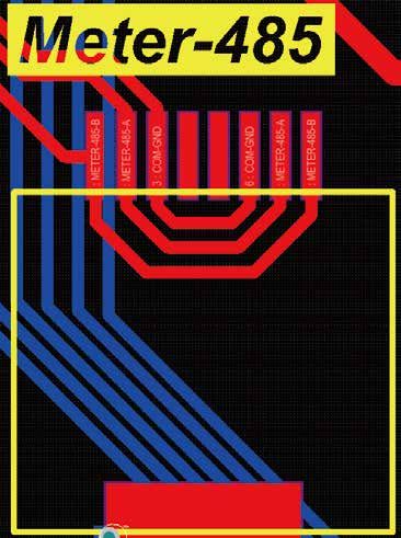
Defini�on of RJ45 Port Pin for Meter-485
No. Meter-485 Pin 12345678
Meter-485 Port
1 METER-485_B
2 METER-485_A
3 COM-GND
4 --
5 --
6 COM-GND
7 METER-485_A
1
2
3
4
5
6
7
8
8 METER-485_B
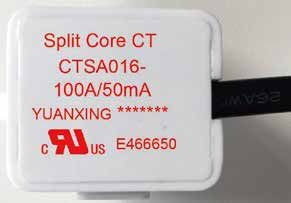
- 39 -11. Appendix III
1. Split Core Current Transformer (CT) dimension: (mm)
2. Seconddary output cable length is 4m.
Lead Outside
- 40 -Add: No.26-30, South Yongjiang Road, Beilun, 315806, Ningbo, China Tel: +86 (0) 574 8622 8957 Fax: +86 (0) 574 8622 8852 E-mail: service@deye.com.cn Web: www.deyeinverter.com 502012252 Ver: 2.0, 2021-1
You can also read