Absolute marking system - AMS 500 Guide to using AMS Software v5.0
←
→
Page content transcription
If your browser does not render page correctly, please read the page content below
Installation and user’s manual

Absolute marking system - AMS 500
Guide to using AMS Software v5.0

                                 Power and productivity
                                     for a better world TM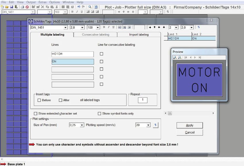
2 | Absolute Marking System - AMS 500
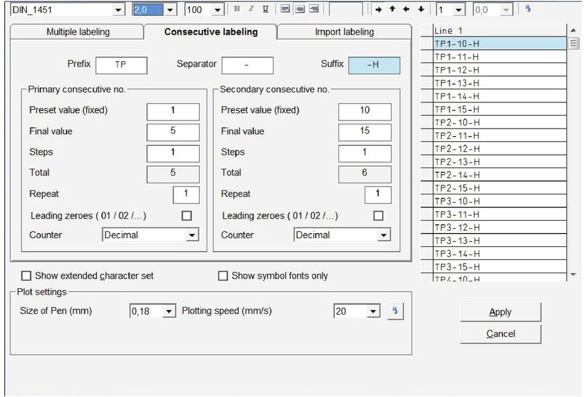
Table of contents

                    1. System requirements........................................................................................................5
                    2. Software installation..........................................................................................................5
                    3. Output devices supported by the program......................................................................5
                    4. General program functions...............................................................................................5
                    5. Brief instructions on how to use the labeling software...................................................6
                       5.1 Choosing the labeling or engraving device....................................................................6
                       5.2 Select the labeling element...........................................................................................6
                       5.3 Labeling elements.........................................................................................................7
                       5.4 Output of labeling data on output device.......................................................................8
                    6. Instructions on how to use the labeling software............................................................8
                        6.1 Choosing the labeling or engraving device....................................................................8
                        6.2 Select the labeling element...........................................................................................8
                        6.3 Labeling elements.........................................................................................................9
                        6.4 Extended input of labeling data...................................................................................10
                        6.5 Multiple labeling..........................................................................................................11
                        6.6 Consecutive labeling............................................................................................. 11-12
                        6.7 Importing labeling data from files........................................................................... 13-14
                        6.8 Insert graphical elements or pictures...........................................................................15
                    7. Output of labeling data...................................................................................................15
                       7.1 Output on plotter.................................................................................................. 15-16
                       7.2 Output on engraver............................................................................................... 16-18
                       7.3 Printing on an office printer................................................................................... 18-19
                       7.4 Printing on thermo transfer printer......................................................................... 20-21
                    8. Create layouts on tags.............................................................................................. 21-23
                    9. Designer / Layouter.........................................................................................................24
                       9.1 Setting up marking tags and strips for plotters...................................................... 24-25
                    		 9.1.1 Design a marking element with one tag group.............................................. 25-26
                    		 9.1.2 Design a marking element with more than one tag group...................................27
                    		 9.1.3 Design marking strips................................................................................... 27-28
                       9.2 Setting up engraving tags for the engraving units.................................................. 28-29
                          9.2.1 Design an engraving element with one tag group.......................................... 30-31
                    		 9.2.2 Design an engraving element with more than one tag group...............................32
                    		 9.2.3 Design a marking strip........................................................................................32
                       9.3 Setting up label sheets for office printers............................................................... 33-34
                       9.4 Setting up endless labels and strips for thermo transfer printers..................................34
                    		 9.4.1 Design an endless label................................................................................ 35-36
                    		 9.4.2 Design an endless strip......................................................................................36
                    10. Import/Export of labeling elements and labels created with various designer
                        versions..........................................................................................................................37
                    11. Special functions using plotter and engraving versions.............................................37
                       11.1 Access of graphic files for plotting or engraving........................................................37
                       11.2 Scale factor........................................................................................................ 37-38
                       11.3 Base plates and segments........................................................................................39
                       11.4 Control print of the labeling data...............................................................................39
                       11.5 Calibrating plotter versions........................................................................................40
                       11.6 Assigning the support plate to the labeling element...................................................40

                                                                                                             Absolute Marking System - AMS 500 | 3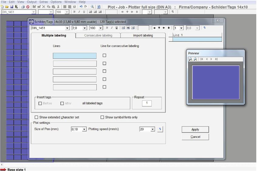
Table of contents

                                        12. General information and adjustments..........................................................................40
                                           12.1 Zoom function..........................................................................................................40
                                           12.2 Select program language..........................................................................................40
                                           12.3 Display and switching within open project files.................................................... 40-41
                                           12.4 Specifying the standard font type..............................................................................41
                                           12.5 Presetting the standard pen size...............................................................................41
                                           12.6 Software version.......................................................................................................41

4 | Absolute Marking System - AMS 500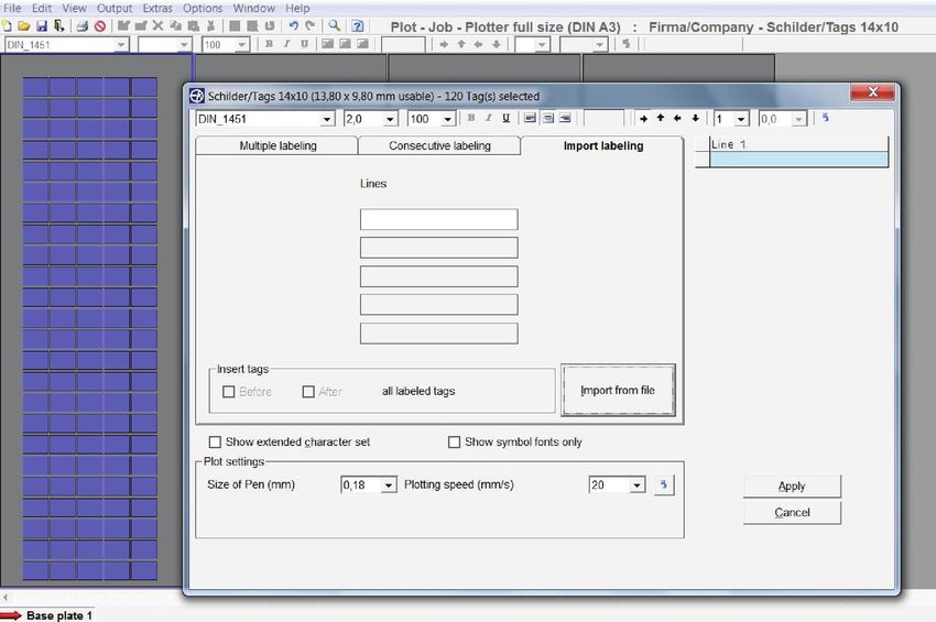
System requirements • Software installation • Output devices
supported by the program • General program functions

1. System requirements
PC with 1.8 GHz (min.), 512 MB RAM, graphic resolution 1024 x 768, 40 GB hard drive, USB interface / Windows 2000, XP,
Vista and Windows 7
2. Software installation (if not already installed)
If the software is already installed, first close all other applications. Insert the software installation CD into your CD-ROM drive.
Installation will begin automatically. You should follow the on-screen instructions. If the auto-start feature has been switched
off on your PC, double-click to start the program.
AMS_setup_x.x.xxxx_xxxxxx.exe
When installation is complete, you can start the program by double-clicking on the program icon. Install the driver for the out-
put device from the CD according to your operating system and follow the instructions.
Language selection is automatic according to the country-specific version of Windows. For country-specific versions of Win-
dows where the program provides no individual language version, the English version is automatically installed. You can
override the settings under > Options > Language setting.
3. Output devices supported by the program
The labeling and engraving software version 5.0 supports the following output devices:
- Plotter
Labeling devices for labeling all current labeling elements that are used in switch cabinets and plant construction.
   - Plotter full size (DIN A3)
   - Plotter half size (DIN A4)
   - Plotter Basic half size (DIN A4)

- Engraving Unit
Engraving device for engraving plastic, aluminum and brass plates. Connecting the engraving unit to one of the plotter ver-
sions provides you with access to the following engraving devices:
   - Engraver full size (DIN A3)
   - Engraver half size (DIN A4)
   - Engraver Basic half size (DIN A4)

Note: The plotter versions and the engraving units can be run with this program solely via a USB connection.
- Office printer
  To print any type of label sheet (DIN A4).
- Thermo transfer printer:
  To print endless labels and endless strips
4. General program functions
Basic software structure
Various labeling devices such as plotters, engravers, office and thermo transfer printers can be controlled using the labeling
software. All labeling elements stored in the database are assigned to the relevant labeling devices. When the labeling device
has been selected, the only labeling elements provided will be those that the particular device can print or engrave.
If, for example, the office printer is selected as the output device, the label sheets set up in the database are automatically
provided for selection. The corresponding designer enables new templates for various output devices to be set up quickly and
easily.

                                                                                                    Absolute Marking System - AMS 500 | 5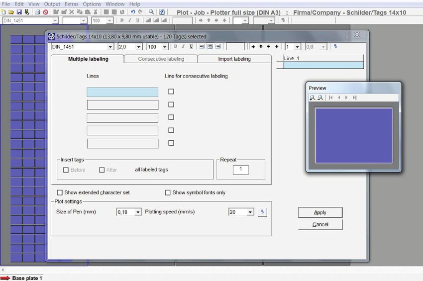
General procedures & instructions for using the labeling software
Select the labeling element

General procedure for using the labeling software
  1. Choosing the labeling or engraving device
  2. Select the labeling element
  3. Labeling elements
  4. Output of labeling data on the output device
5. Brief instruction on how to use the labeling software
5.1 Choosing the labeling or engraving device
From the menu bar, select > File > New project. The window to
select the labeling or engraving device opens. When you have cho-
sen and confirmed the relevant output device, the program provides
you with a list of all labeling element manufacturers for the output
device used.
When you have chosen the plotter or engraver and the respective
device is switched on and connected to your PC via the USB cable,
you can preselect the labeling elements. See Fig 1. In this instance,
the message appears: [Do you want to use the element recogni-
tion function of the plotter or engraver?].

If you confirm by answering Yes, the software imports the identification of
the support plates placed from the plotter and only provides you with the
manufacturers of the labeling elements that can be printed or engraved on
the support plates used.

5.2 Select the labeling element
Click on the relevant manufacturer to select the labeling element required.
It is then displayed on screen.
If you have switched on element recognition for the plotter or engraver, the
individual segments will be displayed on screen. Double-click on the seg-
ment required. This displays only the manufacturers of labeling elements
that can be used with the support plate fitted.
Double-click to select the manufacturer and then the element to be
printed. The relevant template appears on screen,

6 | Absolute Marking System - AMS 500
Labeling elements

The menu bar displays the following information:

   - Plot job       > Output to plotter
   - Engraving job > Output to engraving device
   - Print job      > Output to office or thermo transfer printer
   - Which output device was selected
   - Which labeling element was selected
5.3 Labeling elements
You can choose from a variety of options to label tags or labels.
- Label straight onto the tag
Click on the tag to be labeled. The tag is selected and the tool bar shows the default settings for selecting the font style, font
size, etc.
You can change the settings and enter the labeling text directly.
When you have labeled individual tags, you can copy, insert,
delete, cut or remove tags as well as add new tags. In order to
select and process tags, drag the mouse to the tags that you
want to work on. You can access the action you require by
right-clicking with the mouse on the drop-down menu. Editing
options are based on Excel.
- Extended input of labeling data
If you wish to create multiple labels or con-
secutive labeling, or if you want to import
data from Excel or text files, double-click on
the tag where labeling should begin.
A window subsequently opens enabling you
to use the extended input options to create
labeling data. Click on Apply to go back
show the entries on the tags.

                                                                                                  Absolute Marking System - AMS 500 | 7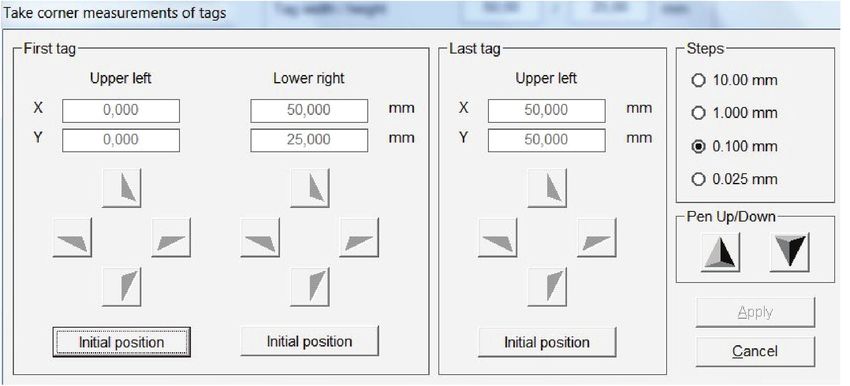
Output of labeling data to the output device • Instruction on how to
use the labeling software • Select the labeling element

5.4 Output of labeling data to the output device
When you have entered all labeling data, click on the printer icon in the tool bar. The window for the relevant output device
appears. You can then use this to enter all the settings you require.
6. Instruction on how to use the labeling software
6.1 Choosing the labeling or engraving device
Follow the menu path > File > New project. The window to select the labeling or engrav-
ing device opens. When you have chosen and confirmed the relevant output device, the
program provides you with a list of all labeling element manufacturers for the output
device used. When you have chosen the plotter or engraver and the respective device is
switched on and connected to your PC via the USB cable, you can preselect the label-
ing elements.
In this instance, the message appears: [Do you want to use the element recogni-
tion function of the plotter or engraver?].

If you confirm by answering Yes, the software imports the identification of
the support plates placed from the plotter and only provides you with the
manufacturers of the labeling elements that can be printed or engraved
on the support plates used.

6.2 Select the labeling element
Click on the relevant manufacturer to select the labeling element required.
If you have switched on element recognition for the plotter or engraver, the individual segments will be displayed on screen.
Double-click on the segment required. This displays only the manufacturers of labeling elements that can be used with the
support plates fitted.
Double-click to select the manufacturer and then the element to be
printed. The relevant template appears on screen.

8 | Absolute Marking System - AMS 500
Labeling elements

The menu bar displays the following information:

   - Plot job       > Output to plotter
   - Engraving job > Output to engraving device
   - Print job      > Output to office or thermo transfer printer
   - Which output device was selected
   - Which labeling element was selected
If the labeling element, label sheet or endless labels are not available in the database, you can use the designer variant to set
these up at any time.
6.3 Labeling elements
You can choose from a variety of data input options to label tags or labels.
- Label straight onto the tag
Click on the tag to be labeled. The tag is selected and the tool bar shows the default settings for selecting the font style, font
size, etc. You can change the settings and enter the labeling text directly. When you have labeled individual tags, you can
copy, insert, delete, cut or remove tags as well as add new tags. In order to select and edit tags, drag the mouse to the tag
that you want to work on. You can access the action you require by right-clicking with the mouse on the drop-down menu.
Editing options are based on Excel.

                                                                                                 Absolute Marking System - AMS 500 | 9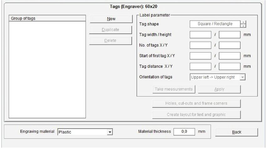
Extended input of labeling data

6.4 Extended input of labeling data
If you wish to set up multiple or consecutive labeling, or if you want to import data from Excel or text files, double-click on the
tag where labeling should begin. A window subsequently opens enabling you to use the extended input options to create
labeling data.

The top line of the window that has now opened provides you with information about the tag or element as well as the number
of tags available. Underneath the line of information, a number of settings are available to change the labeling data. Using the
mouse, if you place the pointer on the relevant icon in the tool bar, the respective function will be displayed.
You can change the following settings: Font style, font size, bold, underline, left align, center, right align, rotate labeling by 90°
at a time, number of lines, line spacing. Changed settings are automatically saved ready for when labeling commences.
Note: The typeface selection in Bold or Italic is only available using the thermo transfer or office printer.
Click on the arrow at the end of the tool bar to restore all factory settings.
In the bottom section of the window, check the < Show extended character set > box. This opens another window that pro-
vides you with special symbols and special characters.
The extended character set provides country-specific characters and special symbols for selection. This means that labels for
other countries can be created without any problem.
Country specific character sets as Baltic, Greek, Turkish, Cyrillic etc. are provided within the typeface ISO_3098. In addition,
serif and ornamental typefaces can be chosen to be used spec. for engraving.
If you have selected a plotter or an engraver as your device, you can modify specific settings with reference to the relevant out-
put device. The settings are displayed in the lower part of the window.
In the middle of the window, you will see three tabs: Multiple labeling – Consecutive labeling – Import labeling

10 | Absolute Marking System - AMS 500
Multiple labeling
Consecutive labeling

6.5 Multiple labeling
The relevant number of lines for editing will be opened according to the number of lines set for each tag. You can now enter a
suitable text and specify the number of tags to be labeled with the same text in the > Repeat field. The entries are displayed in
the preview window. If required, you can also insert blank tags before or after the tags you have labeled.

6.6 Consecutive labeling
If you need to number labels consecutively, you should first specify the number of lines on the Consecutive labeling tab in
which the consecutive numbering should be inserted. To enable you to do this, the > Lines for consecutive labeling field is
activated after the relevant lines.
After this, the program opens the consecutive labeling tab and the consecutive labeling entries can then be added. You can
enter the initial value, final value, text prefix, text suffix, steps, counter and the number of repeats. You can opt for counting to
be ascending, i.e. the initial value is smaller than the final value, or descending, i.e. the initial value is larger than the final value
The window is split into two sections: primary consecutive number and secondary consecutive number. This enables you to
create two consecutive numbers that are linked to one another. You can choose whatever you like as a separator.

                                                                                                      Absolute Marking System - AMS 500 | 11
Consecutive labeling The example shows the primary range TP 1 to 5 and the secondary range 10 to 15-H, - has been selected as the separator, TP is thus the prefix text and –H is the suffix text. The entries are displayed in the preview window. When you click on the Apply button, the program takes you back to the previous tab. If necessary, you can now add blank tags in front of each labeled tag. Likewise, you can specify the number of series in the > Repeat field in the Multiple labeling tab. 12 | Absolute Marking System - AMS 500
Importing labeling data from files
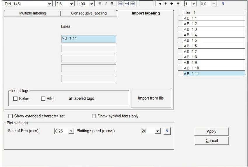
6.7 Importing labeling data from files
If you click on the Import labeling tab, you can import data from files. You can copy data from CAD/CAE programs, E-plan,
text files or spreadsheet programs.
An efficient transfer help tool is available to do this, which enables you to extract data from various file formats.
Click on the Import from file button to search for the file to be imported, then select it by clicking on the file name and finally
click Open to prepare the file for importing.
A window opens up and the file to be imported is entered into a table.
Absolute Marking System - AMS 500 | 13Importing labeling data from files In this example, an Excel file was chosen. You can now select certain fields, sections or individual cells and copy the selected data by clicking on the Selected fields button. You can also copy all the data from the file by clicking on the All fields button. When you have finished copying, click on the Apply button. This will close the window and the data will be displayed in the previous window. Note: If you are importing data from text files, the data is not usually in a format available for use. Various separators are avail- able to enable you to separate the data properly. You can use individual separators, or a combination of separators, such as Tab, Space, Comma or Semicolon. You can also use other characters or letters. You can activate this functionality by checking the Other box and then specifying your require- ment in the subsequent field, e.g. the letter B. Enter B in the empty field and confirm your entry by clicking on OK. Another option for separating when importing is to enter the number of characters. Select Fixed text length and enter the number of characters after which a field separation should be inserted, e.g. 4. Enter 4 in the empty field and confirm your entry by clicking on OK. If you want to import an Excel, Access or E-plan file, the program automatically recognizes the type of file it is dealing with and provides the first record or worksheet to be copied. You have the option of selecting additional worksheets or tables for this file. The first worksheet or the first table are displayed by default. 14 | Absolute Marking System - AMS 500
Insert graphical elements or pictures • Output of labeling data
Output on plotter

6.8 Insert graphical elements or pictures
If you have selected an office printer or thermal transfer printer for printing the labels, you can place as well graphics or pic-
tures with the format JPEG, Bitmap or GIFF. Highlight the label and select from the main menu > Edit > Insert picture or click
on the icon insert graphic or picture.
Browse for the graphical element you want to insert and confirm with OPEN. The element will be shown on all endless labels
and on all labels of the sheets. If you have used the layout function for dividing the label into text fields prior to placing the
graphical element, each text field can also hold a graphical element. In addition the graphical element can be rotated in 90°
steps. To delete the graphic or picture click on the respective icon or go from the main menu to > Edit > Delete picture.

7. Output of labeling data
After entering all labeling data, the labeled tags can be printed or engraved. When you began working, you selected the print-
ing or engraving device you wanted to use. If you click on the Print icon, the relevant printing output window opens for the
output device being used.
7.1 Output on plotter
The settings and information are entered or are displayed on the tabs:
Plot options – Support plates
Plot options tab
This tab enables you to set the following parameters:
- Only use pen inserted in pen holder
If you check this box, no pen is taken out of the pen
depot. Only the pen inserted directly in the pen holder will
be used. This option is therefore always required if you
need to use pens that are not suitable for the plotter’s pen
depot.

                                                                                                 Absolute Marking System - AMS 500 | 15
Output on plotter • Support plates tab Output on engraver - Priming on pen change If you select priming on pen change, prior to labeling, the pen is taken to the respective priming disk next to the pen depot and is primed so that labeling is clear right from the first tag. - Choose different pen in the pen depot Two or more pens are displayed that should be used for this print instruction. If you just want to use one plotter pen thick- ness, click on this option and choose the pen to be used from the selection that subsequently appears. - Choose plotting speed to be used You can set different speeds for individual labeling sequences. If you just want to use one speed, click on this option and set your required plotting speed from the selection that subsequently appears. - Pen size for graphic elements You have the option of creating layouts on tags. These functions are detailed in the section entitled > Create layouts on tags
Output on engraver

- Only one engraving tool and depth to be used
Two or more engraving tools are displayed that should be used for this
engraving instruction. Click this option if you only want to use one tool
size and depth of penetration.
- Only one engraving speed to be used
Different engraving speeds can be set for individual labeling tasks. If you
just want to use one speed, click on this option and set your required
engraving speed from the selection that subsequently appears.
- Choose RPM to be used
You can set different RPMs for the engraving spindle for individual label-
ing tasks. If you just want to use one spindle speed, click on this option
and set the spindle speed required (RPM) from the selection that subse-
quently appears.
- Only one penetration speed to be used
You can set different speeds for individual labeling sequences. If you just want to use one speed, click on this option and set
your required penetration speed from the selection that subsequently appears.
- Reverse labeling
This function enables you to reverse the labeling, thus effectively labeling the tag from behind. This produces a label that can
be read on the front without the surface of the tag having been engraved. This makes it impossible to leave behind any dust
particles in the engraving itself (certain materials required).
- Speed for graphic elements
You have the option of creating layouts on tags. These functions are detailed in the section entitled > Create layouts on
tags
Output on engraver • Support plates tab
Printing on an office printer

- Engrave holes on tags with lettering only
If you select this function, holes, if designed, will be engraved only on tags containing lettering.
- Engrave holes on all tags
If you select this option, holes, if designed, will be engraved on all tags.
- Engrave tag contour only
Checking this box will enable you to just engrave the tag contours. You can use this option with thick materials to engrave
contours in a two-stage process, if necessary. First choose a small depth of penetration and then fully engrave the material.
- Speed for tag contour
You can use this section to set the engraving speed, the revolution speed (RPM) of the engraving spindle and the penetration
speed for the engraving spindle for the material being engraved.
Note: In principle, lettering is always engraved first, followed by the contours, as long as the relevant parameters have been
set.
After the engraving job, the engraving device stops and asks if you require to fit another engraving spindle and set another
penetration depth, so that the material can be engraved right through to the base. With thick materials, this can be done in
two stages.
Support plates tab
This shows which labeling elements are being used and checks whether the relevant support plate has been fitted for the
engraver. If a support plate is missing or if the support plate is not compatible with the labeling element, the corresponding
segment is highlighted in red.
Note: The Plotter Basic half size (DIN A4) has no support plate
recognition and therefore no check can be made to ensure the cor-
rect support plates have been fitted.

7.3 Printing on an office printer
The first time you send your data to be printed on an office printer, the following message appears on screen:

18 | Absolute Marking System - AMS 500
Printing on an office printer
Printing on a thermo transfer printer

When you confirm the message by clicking on OK, a window opens with the Printer tab showing all printers available:

Now choose the printer you require and click on the Test page button. A < Portrait test page > sheet is then printed on the
relevant printer. Measure the top and left margin with a ruler and enter the values in the respective boxes. These entries are
needed because all printers have different margin settings for text.
Click on OK to save these values. The program will then take you to the Print options tab, where you can set the following
parameters for the printout.
- Specify the number of label sheets to be printed.
- Specify whether only the selected tags should be
printed.
- Specify whether a frame should be printed around
the lettering. This function is useful if you want to cut
out printed tags with scissors.

If you check this box, the program automatically
takes you to the Tag contours tab.
By clicking the relevant box, you can choose
whether to plot a frame around tags with lettering
only or to plot a frame around all tags on the sheet.
If you select Plot frame only, only the frames with-
out the lettering will be printed

                                                                                              Absolute Marking System - AMS 500 | 19
Printing on a thermo transfer printer 7.4 Printing on a thermo transfer printer The first time you send your data to be printed on a thermo transfer printer, the following message appears on screen: When you confirm the message by clicking on OK, a window opens with the Endless Printer tab showing all printers avail- able. Now select the TT printer required. The < Increase size of tag > setting enables you to adjust lengths for unlimited strips (Scale factor). Click on Apply and then OK to save these settings. The program will then take you to the Print options window, where you can set the following parameters for the printout: - Specify the number of prints required. - Enter the distance from left margin of the printing area. - Specify whether only the selected tags should be printed. 20 | Absolute Marking System - AMS 500
Printing on a thermo transfer printer
Create layouts on tabs

By clicking on the tab Strip options you can modify the strip output.

- Increase size of tags to compensate width of terminal blocks
With the change of the value the width of the tag segments can be adapted to the terminal block size.
- Raster mark showing as
Selecting, if raster mark should be plotted, either All after each segment, Last only at the end of last segment or None.
- Raster mark
Selecting, if raster mark should be plotted as Line or Dot.
8. Create layouts on tags
If you want to arrange text fields or graphic elements on tags, the program has a user-friendly layout option that you can use
for this purpose. This function is helpful when you want to divide a tag into various fields. It gives you the opportunity to use
various font styles, font sizes and symbols in the individually created text fields. This function is also useful if you want to create
individual labeling fields on prefabricated rating plates.
Call up the tag for which you need to create a layout, select a tag and select > Edit tag layout from the drop-down menu.

                                                                                                   Absolute Marking System - AMS 500 | 21
Create layouts on tabs After choosing the layout, the following window appears on screen. The tag size is displayed in the top left field of the window. Underneath that, you will see various components available that you can set up on the tag. For example, if you want to create a text field with frame, click on the relevant component. You should then use the mouse to position the cursor in the right- hand side of the window in the tag displayed there, click with the mouse to specify where the text field should begin, and use the mouse to define the text field. This will create your text field. Now you can click on the text field and move it to wherever you want it. You can also enter the coordinates, such as the dis- tance from the margin, height and width of tag, directly into the relevant fields and confirm by pressing Enter. The entry is immediately applied and the preview is updated. Note: It is easy to inadvertently move the graphic elements you have created when you click on them with the mouse. In order to avoid moving the elements in error, you can fix their positions by calling up the drop-down menu. After fixing the position, you can also change the coordinates, size and position of graphic elements. If you are using a plotter or engraver as your output device, you can measure the text fields with the plotter. To do this, click on the text field whose measurements you wish to take and select > Take Measurement of text field function from the drop- down menu. 22 | Absolute Marking System - AMS 500
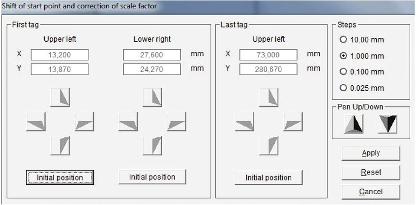
Create layouts on tabs

The following window opens up:
Insert a pen directly into the writing arm pen holder and click on
the left Initial position button. The plotter moves to upper left
corner of the total plot area. You can now go to the text field in
the top left-hand corner and use the cursor key to take the tip of
the pen right to the corner of the text field. You can choose the
step size for each click of the cursor button.
Once you have defined the upper left corner, go to the lower
right corner of the text field by clicking on the second Initial
position button. Proceed as before. When you click on Apply,
the coordinates will be applied.
You can duplicate or delete components that have been
created.
You also have options available for setting the alignment of text
fields or graphic elements that have been set up.

If, as shown in the example, you have used the mouse to click on the three components while holding down the Control key
and then clicked on the Vertical alignment button, the elements created are aligned vertically. Other layout options are
available.
You can alter the size of the preview window to make it larger or smaller. Once the layout is completely finished, there are two
options available for you to apply the layout. Click on the Apply button to apply the layout to the previously selected tags. You
can now enter labeling data straight into the fields.
If you want to save this layout on the tags, click on the Save as button. You then need to save this tag with the layout you
have created with a new name. When you want to use this labeling element with the layout at a later date, you can call up the
labeling element in the > User defined folder.

                                                                                               Absolute Marking System - AMS 500 | 23
Designer / Layouter
Setting up marking tags and strips for plotters
9. Designer / Layouter
This is used for setting up your own marking elements, label sheets, endless labels or endless strips, engraving tags or rating
plates for engraving.
There are 4 different versions of the Designer/Layouter. These can be selected on the menu by clicking on > Extras > Designer
/Layouter for:
- Tags and strips (Plotter)
- Tags (Engraver)
- Label sheets (Office printer)
- Endless labels and strips (Thermo transfer
printer)
9.1 Setting up marking tags and strips for plotters
The Designer is called up using the following menu item: > Extras > Designer/Layouter for > Tags and strips (Plotter).
The following window opens up: Here you can create a new marking element by clicking on the New button. First enter the
name of the marking element you wish to create in the left-hand window.
Next, you have to make the following settings:
Use the plotter’s support plate recognition function.
If you have a plotter with support plate recognition, it is
advisable to use this function to make it easier later on
to find the marking element that you have created. To
do this, the plotter must be switched on and the rele-
vant support plate positioned on the plotter.
If you do not want to use support plate recognition, or
are using a plotter with no support plate recognition
function, click on Specify type of support plate. Now
you have to select the support plate on which you
want to set up the tag or element.
In the next stage you define the properties of the mark-
ing element.
24 | Absolute Marking System - AMS 500Setting up marking tags and strips for plotters
Design a marking element with one tag group
Here you can choose between three options:
- Design tags within single group
The marking element has only one tag size.
- Design tags within multiple groups
The marking element has two or more tag sizes.
- Design strips
With this function you can create marking strips with the size needed, dividing them into horizontal and vertical sections.
Selecting one of the dividing directions opens another window for entering the additional strip parameter.
9.1.1 Design a marking element with one tag group
Enter the tag parameters for the marking element.
If you do not have the exact data to hand, it is easy to use the plotter
to measure the tags (recommended).
To measure using the plotter, all you have to enter is the number of
tags along the X- and Y-axes. All the other data can be easily calcu-
lated using the program and with the help of the plotter.
You can also specify the sequence in which the tags will be labeled.
The sequence for labeling can either be from Upper left > to Upper
right (line by line), or from Upper left > to Lower left (column by
column).
Absolute Marking System - AMS 500 | 25Design a marking element with one tag group Attention: For processing to continue, it is essential that the plotter is switched on and the marking element which is to be set up is posi- tioned on the plotter, with the appropriate support plate. Insert a pen directly into the plotter’s pen holder. As an option, there is also an optical measuring tool available which you can use to calculate and specify the tag parameters. This tool is inserted like a pen directly into the plotter’s pen holder. When you have entered all or just some of the tag parameters, but at least the number of tags along the X- and Y-axes, click on the Take measurements button and the following window opens up: To take measurements, proceed as follows: First of all, specify the exact position of the upper left corner of the first tag in the matrix. To do this, click on the Initial posi- tion button left in the first tag window. The plotter’s writing arm now moves to the upper left corner of the plotter field. You can use the relevant cursor buttons as shown to move to the exact position of the upper left corner of the first tag. You can choose the step size for each click of the cursor at the top right of the window. When you have moved to the posi- tion for the corner, you can use the Pen Up/Down button to check that you have reached the exact position. The relevant coordinates are displayed in mm, from the starting position of zero. Now specify the exact position of the lower right corner for the first tag. Do this following the same procedure as detailed above for locating the upper left corner. Now specify the upper left corner of the last tag in this matrix. Go to the last tag bottom right and proceed just as before. Specifying these three points completes all measurements for this marking element. You can now save the values you have calculated by clicking on the Apply button. The < Take measurements > window is closed and the program takes you back to the previous page. If you also click on the Apply button here, you will see the marking element that has been set up. You can now check that all data have been correctly calculated. If any error messages or notices are displayed, you should check your data again or allow automatic correction. Having completed the marking element, you now also have the option of positioning text fields and graphic elements on the tags. Creating text fields like this is always useful if you want to divide the tag up into different fields, so that you can later use different text sizes, font types or symbols on the tag. See Section 8 of this manual for information on how to set up a layout. After you have specified the design and, if you wish, also the layout, click on Back to close the Designer or Layouter. The pro- gram takes you back to the main window, which you can then close by clicking on the Close button. You can select the labeling element you have created in the folder > User defined under > Manufacturer and call it up for lettering. 26 | Absolute Marking System - AMS 500
Design a marking element with more than one tag group
Design marking strips

9.1.2 Design a marking element with more than one tag group
To set up groups of tags of different sizes, you proceed
exactly as described in the previous section.
In order to assign the tag groups, on the left of the window
you must specify appropriate names for the different tag
groups. Once you have specified the name for a tag group,
you can then enter the tag parameters and measure the tags
and then create a layout if required. When you have finished
one tag group, you can set up more tag groups.

9.1.3 Design marking strips
You have already specified the name for the marking strip, X-strip.

The next thing to do is to define the strip parameters: First select the alignment of the strip. Lay the strip(s) vertically or horizon-
tally on the plotter. Then enter the length and width of the strip, followed by the number of strips lying on the plotter. By using
the Take measurements function, it is easy to calculate the start coordinates and the strip spacing. Proceed exactly as
described in the previous section.
After you have measured the strips and pressed Apply, you can specify a layout for the strips in the right-hand section of the
window. You can subdivide the individual strips using horizontal and vertical scale factors.
First, if required, divide the strips into horizontal sections. Then define the height of the first section, by entering the height in
mm in the > Partition 1 field. The remaining height is then transferred into > Partition 2. In this way, you can subdivide the strips
into a maximum of 5 partitions. When you have finished dividing them up into sections, first click on the Apply button. This
completes the horizontal subdivision.

                                                                                                    Absolute Marking System - AMS 500 | 27
Design marking strips
Setting up engraving tabs for engraving units
Next, you can make a vertical subdivision for each partition. Click on Crosswise for the relevant strip.
Then the following window opens up:
To enter the required subdivision of the strip, proceed as follows:
First enter the width and then the number of tags. By clicking on the Add button, the data are
transferred to the field below. If the strip is not yet fully divided up, you will be shown the length
of strip that is still available. Now you can specify other tag widths.
When you click on Apply, the program takes you back to the previous window and displays the
subdivision that you have specified. In this way you can subdivide the individual partitions using
different tag widths in succession as required.
When you have finished all the subdivisions, close the Designer. You can select the labeling ele-
ment you have created in the folder > User defined under > Manufacturer and call it up for
labeling.
Note: If you have created the labeling data for a strip and are producing the plotting data on the
plotter, there is the opportunity to define various options for plotting.
On the index card Strip options, you can determine whether cutting marks as separating lines
or dots should also be plotted.
9.2 Setting up engraving tags for engraving units
Call up the Designer under > Extras > Designer/Layouter for > Tags (Engraver).
The following window opens up:
Here you can create a new engraving element (individ-
ual tags or tag groups) by clicking on the New button.
First enter the name of the engraving element you wish
to create in the left-hand window.
Then you can define whether you want to use the
plotter`s support plate recognition function.
Use the plotter`s support plate recognition function.
If you have a plotter unit with support plate recognition,
it is advisable to use this function to make it easier later
on to find the engraving element that you have created.
To do this, the plotter must be switched on and the rel-
evant support plate positioned on the plotter. If you do
not want to use support plate recognition, or are using
a plotter with no support plate recognition function,
click on < Specify type of support plate >.
Now you have to select the support plate on which you want to set up the element. Then you define the engraving material
and enter the thickness of the material in the box at the bottom of the window.
28 | Absolute Marking System - AMS 500Setting up engraving tags for engraving units
In the next stage you define the properties of the marking element. Here you can choose between two options:
- Design tags within single group
The engraving element has only one tag size.
- Design tags within multiple groups
The engraving element has two or more tag sizes.
- Design strips
With this function you can create marking strips with the size needed, dividing them into horizontal and vertical sections.
Selecting one of the dividing directions opens another window for entering the additional strip parameter.
With this function you can create marking strips with the size needed, dividing them into horizontal and vertical sections.
Selecting one of the dividing directions opens another window for entering the additional strip parameter.
Absolute Marking System - AMS 500 | 29Design an engraving element with one tag group
9.2.1 Design an engraving element with one tag group
Now there are various ways you can create your engraving tags.
- You want to create your tags on a blank plate.
First define the shape of the tag, square/rectangle or circle/ellipse. Then enter the required tag size. Now click on < Auto-
matic tag partitioning >. When you click on the Apply button, the tags you have created will be displayed.
- You want to enter the data for an existing tag plate.
Enter the tag parameters for the pre-existing tag plate.
If you do not have the exact data on hand, it is easy to use the engraver to measure the tags (recommended).
To measure using the engraver, all you have to enter is the number of tags along the X- and Y-axes. All the other data can be
easily calculated using the program and with the help of the engraver. To do this you need the optical measuring tool that you
will receive from us.
You can also specify the sequence in
which the tags will be labeled. The
sequence for labeling can be either from
upper left > to upper right (line by line), or
from upper left > to lower left (column by
column).
Attention:
For processing to continue, it is essential
that the engraver is switched on and the
engraving element which is to be set up
is positioned on the engraver, with the
appropriate support plate. First take the
engraving spindle out of the engraving
head and then insert the optical measur-
ing tool into the engraving head.
When you have entered all or just some
of the tag parameters, but at least the
number of tags along the X and Y axes, click on the Take measurements button and the following window opens up:
To take measurements, proceed as follows:
First of all, specify the exact position of the upper left cor-
ner of the first tag in the matrix. To do this, click on the
Initial position button left in the first tag window. The
engraver’s engraving arm now moves to the upper left
corner of the engraving field. You can use the relevant cur-
sor buttons as shown to move to the exact position of the
upper left corner for the first tag.
You can choose the step size for each click of the cursor
at the top right of the window. Go to the exact position of
the top corner. The relevant coordinates are displayed in
mm, from the starting position of zero. Now specify the exact position of the lower right corner for the first tag.
Now specify the upper left corner of the last tag in this matrix. Go to the last tag bottom right and proceed just as before.
Specifying these three points completes all measurements for this engraving element. You can now save the values you have
calculated by clicking on the Apply button. The < Take measurements > window is closed and the program takes you back
to the previous page.
30 | Absolute Marking System - AMS 500Design an engraving element with one tag group
If you also click on the Apply button here, you will see the engraving element that has been set up. You can now check that all
data have been correctly calculated. If any error messages or notices are displayed, you should check your data again or allow
automatic correction. Now the engraving element is created.
If you now want to make holes or cutouts in the tags you have created, or round off the corners, click on the Holes, cut-outs,
frame corners button. The following window then opens up:
Here you can round off the corners by clicking on the Round frame cor-
ners field and selecting the radius.
You also have the option of making holes or cutouts in the tag. To do this,
go to the tag and with the mouse draw a circle or a cutout. Later you can
use the coordinates to define the position and size of the circle or cutout
exactly.
There are a number of alignment functions available.
Use the Apply button to save the data and close the window.
Having completed the engraving tags, you now also have the option of
positioning text fields and graphic elements on the tags. Creating text
fields like this is always useful if you want to divide the tag up into different
fields, so that you can later produce different text sizes, font types or sym-
bols on the tag.
To do this, click on the Layout for text and graphics button. See Section
8 of this manual for a description of how to set up a layout.
After you have specified the design and, if you wish, also the layout, click
on Back to close the Designer or Layouter.
The program takes you back to the main window, which you can then
close by clicking on the Close button.
You can select the engraving element you have created in the folder
> User defined under > Manufacturer and call it up for engraving.
Absolute Marking System - AMS 500 | 31Design an engraving element with more than one tag group Design a marking strip 9.2.2 Design an engraving element with more than one tag group To set up groups of tags of different sizes, you proceed exactly as described in the previous section. In order to assign the tag groups, on the left of the window you must specify appropriate names for the different tag groups. Once you have specified the name for a tag group, you can then enter the tag parameters and measure the tags and then, if you wish, add holes, cut- outs and radii. Then a layout can be created. When you have finished one tag group, you can set up more tag groups. 9.2.3 Design marking strips You have already specified the name for the marking strip, X strip The next thing to do is to define the strip parameters: First select the alignment of the strip. Lay the strip(s) vertically or hori- zontally on the engraver. Then enter the length and width of the strip, followed by the number of strips lying on the engraver. By using the < Take measurements > function, it is easy to calculate the start coordinates and the strip spacing. Proceed exactly as described in the previous section. After you have measured the strips and clicked on Apply, you can specify a layout for the strips in the right-hand section of the window. You can subdivide the individual strips using horizontal and vertical scale factors. First, if required, divide the strips into horizontal sections. First define the height of the first section, by entering the height in mm in the > Partition 1 field. The remaining height is then transferred into > Partition 2. In this way, you can subdivide the strips into a maximum of 5 partitions. When you have finished dividing them up into partitions, first click on the Apply button. This completes the horizontal subdivision. 32 | Absolute Marking System - AMS 500
Setting up label sheets for office printers

Next, you can make a vertical subdivision for each partition. Click on Crosswise for the relevant strip. Then the following win-
dow opens up:
                               To enter the required subdivision of the strip, proceed as follows:
                               First enter the width and then the number of tags. By clicking on the Add button, the data are
                               transferred to the field below. If the strip is not yet fully divided up, you will be shown the length
                               of strip that is still available. Now you can specify other tag widths.
                               When you click on Apply, the program takes you back to the previous window and displays the
                               subdivision that you have specified.
                               In this way you can subdivide the individual partitions using different tag widths in succession as
                               required. When you have finished all the subdivisions, close the Designer.
                               You can select the labeling element you have created in the folder > User defined under > Manu-
                               facturer and retrieve it for labeling.
                               Note: If you have created the labeling data for a strip and are producing the engraving data on
                               the engraver, the horizontal and vertical separating lines will be engraved.

9.3 Setting up label sheets for office printers
Call up the Designer under > Extras > Designer / Layouter for > Label sheets (Office printer).
The following window opens up:
                                                      Here you can create a new label sheet by clicking on the New button.
                                                      First enter the name of the label sheet you want to create in the window.

                                                                                                 Absolute Marking System - AMS 500 | 33
Setting up label sheets for office printers
Setting up endless labels and strips for thermo transfer printers
Then click on Edit and another window opens:
Now you have to enter the appropriate tag parameters for your label sheet
here. If you do not have the data directly to hand, then you must enter the
width and height of the tag, the distance from the top left-hand corner of
the first tag (start coordinates) and the tag spacing along the X- and
Y-axes, using a ruler. You also have to enter the number of tags along
the X- and Y-axes.
You can also specify the sequence in which the tags are printed. The
sequence for labeling can be either from upper left > to upper right (line by
line), or from upper left > to lower left (column by column).
When you click on the Apply button, the tags you have created are dis-
played on the screen.
Having completed the labels, you now also have the option of positioning
text fields and graphic elements on the labels. Creating text fields like this
is always useful if you want to divide the label up into different fields, so
that you can later use different text sizes, font types or symbols on the
label.
To do this, click on the Create layout for text and graphic button. See
Section 8 of this manual for a description of how to set up a layout. After
you have specified the layout if you wish, click on Back to close the Layouter.
The program takes you back to the main window, which you can then close by clicking on the Close button. You can select
the labeling element you have created in the folder > User defined under > Manufacturer and call it up for printing.
9.4 Setting up endless labels and strips for thermo transfer printers
Call up the Designer under > Extras > Designer for > Endless labels and strips (Thermo transfer printer).
The following window opens up:
You can now create new endless labels or endless strips here by clicking on the
New button. First enter the name of the label or strip that you want to create in
the window.
Now you have to specify whether you want to create an endless label or an
endless strip. Click on either Label or Strips. After you click on one of those
options, the relevant window opens.
34 | Absolute Marking System - AMS 500Design an endless label
9.4.1 Design an endless label
Enter the width and height of the tag here. If, on your endless roll, you have more than one label side by side, enter the number
of labels in the appropriate field.
You must also enter the tag distance in X and Y.
Tag distance X
Tag height
Tag distance Y
Tag width
Note: When the labels are subsequently printed out on a thermo transfer printer, the tag spacing along the Y-axis is detected
by a light barrier. The entry on the tab only serves to ensure that it displays correctly on the screen.
Absolute Marking System - AMS 500 | 35Design an endless label
When you click on the Apply button, the tags you have created are displayed on the screen. Having completed the labels, you
now also have the option of positioning text fields and graphic elements on the labels. Creating text fields like this is always
useful if you want to divide the label up into different fields, so that you can later use different text sizes, font types or symbols
on the label. To do this, click on the Create layout for text and graphic button.
See Section 8 of this manual for a description of how to set up a layout.
After you have specified the layout, if you wish, click on Back to close the Layouter. The program takes you back to the main
window, which you can then close by clicking on the Back button. Click on Close to close the Designer. You can select the
labeling element you have created in the folder > User defined under > Manufacturer and retrieve it for printing.
9.4.2 Design an endless strip
First decide on the size of the strip and enter its length and width. Then you
can divide up the strip using horizontal and vertical scale factors.
If required, divide the strip into horizontal sections. First of all, specify the
height of the first partition, by entering the height in mm in the > Partition 1
field. The remaining height is then transferred into > Partition 2. In this way
you can subdivide the strip into a maximum of 5 partitions.
When you have finished dividing the strip into partitions, you first click on the
Apply button. This completes the horizontal division. After that, you can
make a vertical division for each partition. Click on Crosswise for the relevant
strip.
Then the following window
opens up:
To enter the required subdivi-
sion of the strip, proceed as
follows: First enter the tag
width and then the number of tags.
By clicking on the Add button, the data is transferred to the field below. If the
strip is not yet fully divided up, you will be shown the length of strip that is still
available. Now you can specify other tag widths.
When you click on Apply, the program takes you back to the previous window
and displays the subdivision that you have specified.
In this way you can subdivide the individual partitions using different tag widths
in succession as required. When you have finished all the subdivisions, Close
the Designer.
You can select the labeling element you have created in the folder > User
defined under > Manufacturer and call it up for printing.
Note: If you have created the labeling data for a strip and are printing out the
print data on a thermo transfer printer, there is the opportunity to define vari-
ous options for printing. You can determine whether cutting marks as
separating lines or dots should also be printed.
36 | Absolute Marking System - AMS 500You can also read