Standardization and safety control generation for SNCF systems engineer
←
→
Page content transcription
If your browser does not render page correctly, please read the page content below
Preprints of the 19th World Congress
The International Federation of Automatic Control
Cape Town, South Africa. August 24-29, 2014
Standardization and safety control generation for SNCF systems engineer
Raphaël Coupat1&2, Marc Meslay1, Marc-Axel Burette1, Alexandre Philippot2, David Annebicque3, Bernard Riera2
raphael.coupat@univ-reims.fr
1
PSIGT-TE (CES), Direction de l’Ingénierie, Société Nationale des Chemins de Fer Français,
6, avenue François Mitterrand – 93574 La Plaine Saint Denis CEDEX, France
2
CReSTIC (EA3804), Université de Reims Champagne-Ardenne
Moulin de la Housse, BP 1039, 51687 REIMS CEDEX 2, France
3
CReSTIC (EA3804), IUT de Troyes, 9 rue de Québec, BP 396, 10026 TROYES, CEDEX, France
Abstract: This paper presents an original approach developed within an industrial thesis, financed by the
SNCF (French acronym for National Society of French Railways). The aim is to standardize the work of
electric traction of railway transportation. This approach is composed of two axes. Firstly, a standardized
generation of deliverables is done to help the systems engineers keeping their concentration on cognitive
task and to avoid repetitive tasks which can lead to mental underload. Secondly, a robust filter based on
the use of safety constraints is integrated. This controller is then constrained by the functional programs,
already established and used by the SNCF. The system safety is insured by the robust filter which has
been formally verified by model-checking.
Keywords: Power and Energy Systems, Robust Control Design, Social Impact of Automation, Safety-
Critical Systems, Railway Transportation Systems.
1. INTRODUCTION are responsible for the supply of PSEEL under nominal and
degraded modes (maintaining catenary voltage) and safety of
The French national rail network has to face the competition persons working on PSEEL or catenary under national
of the European rail transportation, due to the opening of the regulations (UTE C 18510) or specific (S11, log C) and
market. In order to keep its leadership of the French rail emergency shutdown in case of electrical danger to persons
market, SNCF (French acronym for National Society of and properties.
French Railways) tries to set up innovative solutions
improving the productivity. These solutions shall not threaten The approach integrates two axes of improvement (Fig. 1).
people and installations safety from which the engineering of The first one is the standardization, in order to improve the
the SNCF infrastructure is a guarantor. homogeneity of deliverables made by the technical studies.
Standardization can also integrate the generation of
In SNCF, the electric traction engineering department (IGTE) deliverables (documents, schema...). The deliverables
is in charge of the specification of the equipment of generation optimizes the working time of the systems
telecontrol, automation and Low Voltage (LV) protections of engineers by avoiding them to enter redundant data. The
the Power Supply Equipment of the Electric Lines (PSEEL) improvement of the working conditions involves a regulation
market. To improve productivity and performance, PSIGT- of their mental workload by avoiding the errors. The second
TE implements solutions harmonizing the working axe is the implementation of a robust filter based on safety
environment of the telecontrol, automation and LV constraints (Riera et al., 2012) to ensure the safety of persons
protections design studies, realized on the PSEEL, as and PSEEL whatever is the functional control implemented
specialized project management. Suggested solutions must in Programmable Logic Controller (PLC). This control safety
also be a way to ensure the safety of PSEEL as presented in filtering should be used to prevent control errors that may be
this article. sent from CSS.
The PSEEL are the electrical supply points of the electrified
lines, called catenary. The role of the PSEEL is to transform,
to supply, even to rectifier in the case of DC supply, the
tension of the High-Voltage (HV) network into compatible
tension with traction units (1500 V DC or 25 kV AC). These
electrical systems, under (very) High-Voltage, are subjected
to strict standards of railway safety (EN 50126). The PSEEL
are distributed automated systems among which control-
command can be done locally but also remotely, in a
centralized control station called Central Sub-Stations (CSS).
The human supervisors (Fig. 1) can activate HV devices Fig. 1. Application of standardization and robust filter.
(switches, circuit-breakers…) from this control room. They
Copyright © 2014 IFAC 12128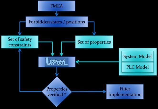
19th IFAC World Congress
Cape Town, South Africa. August 24-29, 2014

This solution is based on the principle of unique data              The work of design and study of the PSEEL, realized by the
entering, this allows optimizing the workload. The                  systems engineers, requires a hard intellectual activity during
description of the PSEEL in this unique software                    the entire project to avoid mistakes. This concentration can
environment will permit to generate all deliverables                be altered by several factors. The most compelling element of
(documents, programs, wiring diagrams ...). This software           concentration alteration, reducing the concentration and
solution must be a part of a process of work standardization.       therefore the effectiveness of the systems engineer, is the
                                                                    plurality of projects which he/she has to realize in a limited
Firstly, the paper presents the domain of electric traction and
                                                                    time. Indeed a number of hours is allocated to each task of a
its associated jobs. Section 3 briefly defines mental workload
                                                                    project, depending on the complexity of the structure of the
concepts. The exhaustive definition has been done in (Coupat
                                                                    PSEEL. The concept of deadline may cause additional stress
et al, 2013). The envisaged solutions are presented to counter
                                                                    (Sargent and Terry, 2000). Within the project workflow, the
these mental workload problems thanks to the approach of
                                                                    multiplication of the realization computing tools of the
standardization, in section 4, and to the robust filter
                                                                    various tasks does not help the systems engineer to optimize
implementation in section 5. Finally, the implementation of
                                                                    his/her working time. The tool switch can lead to a loss of
those solutions in the field of Electric Traction is presented.
                                                                    information and errors while copying. Moreover, a
        2. ELECTRIFICATION PROJECT OF PSEEL                         relationship was shown between the multiplication of
                                                                    resources and working memory which can lead to mental
Electrification project of PSEEL is divided into several
                                                                    overload (Young and Stanton, 2001).
phases (Fig. 2). The project starts with the specifications to
define the needs and constraints of the system. This phase is       This plurality of tools, needed to provide various deliverables
accompanied by the realization of the installation wiring           (documents, programs, wiring diagrams ...), also causes
diagrams describing the architecture and related                    multiple data entering of the same information about a
control/command/protections system. Then the systems                project. This repetitiveness of action, besides being source of
engineer studies and writes the PLC programs, with respect          error and a waste of time, harms in the concentration as well
of conception rules established by IGTE. A set of tests             as in the interest which the systems engineer feels in his work
procedure, grouped within a testing procedures book, must           by the lack of valuation and gratitude. Mental workload is
then be performed to verify and validate the correct operation      therefore reduced, and mental underload comes (Stanton et
of the system and programs. Testing procedures (tests phase         al., 1997). These notions of mental workload are defined in
2) take place in a factory in a first time to validate the wiring   the third part of this paper, dealing with mental workload.
and programs. After a correction phase, the testing                 Furthermore, the systems engineers are a team and work
procedures are realized on site (tests phase 3) to validate the     separately, which can lead to different assessments of the set
full system and electric command of HV devices. Validation          up principles.
of testing procedures book ensures the safety of the system.
                                                                                     3. MENTAL WORKLOAD
The safety of the control system of PSEEL requires
introducing the dreaded critical event. This dreaded event is       The mental workload (ISO 10075) in the automation field is a
an unwanted command of a device (opening or closing),               major concern since a few years. This persistent notion has
which would lead to serious consequences and could                  never been completely surrounded and is a part of the social
jeopardize the physical human safety. This is why the field of      debate related to work intensification (Askenazy and Caroli,
electric traction is subject to robust constraints of safety of     2003). It is defined as the quantitative or qualitative measure
the functioning (EN 50126). The systems engineer is                 of the level of activity required to perform a specific work
responsible for validating the specifications, testing              (Sperandio, 1988). In other words, the concept of mental
procedures once completed by realized tests and insuring the        workload is defined fundamentally in terms of the
integrity of the system. PLC programs implemented by the            relationship between the supply (resources) and demand
systems engineer must also be validated during tests phase.         (requirements) (Wickens, 1984). The workload is a complex
                                                                    concept which use has been extended to many areas of
The design rules of the programs are described within the           psychology and ergonomics (Millot, 1987). The task itself
principles of PSEEL automation (Fig. 2) through GRAFCET             and its constraints are included under the name of
(IEC 60848) specifications describing the sequential HV             requirements of the work. The effort corresponds to the cost
functioning of devices.                                             of mental work, so appearing as the result of the mobilization
                                                                    of all the mental functions involved by the operator to realize
                                                                    a task (Lancry and Lammens, on 1998) (Fig. 3).

Fig. 2. Division of the project phases of electrification.
                                                                    Fig. 3. Inverted-U curve showing the influence of workload
                                                                    on performance.

                                                               12129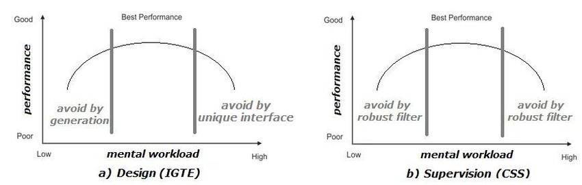
19th IFAC World Congress
Cape Town, South Africa. August 24-29, 2014

To improve the team performance to design electrification          cognitive task asks for more concentration of the systems
projects, the homogenization of documents and deliverables         engineer because it is about the documents validation which
seems to be an effective solution. Indeed, through                 he/she would have to write previously (but not anymore).
standardization, it is possible to improve performance and         This phase of proofreading also allows the systems engineer
quality by defining rules in order to make the reading of a        to have a critical look on the generated elements. This
project easier for everyone. This article will also show that      feedback allows improving the generation. He/she must be
the safety aspect of the approach, improves mental workload        concentrated to analyze the lacks and complete the generated
of the systems engineers.                                          elements.
            4. STANDARDIZATION PROCESS                             The concentration of the systems engineer is then focused on
                                                                   a new task, in which he/she has to describe only once all the
Standardization of a job is a process requiring the domain
                                                                   parameters of the design project of the PSEEL to generate the
know-how and having a global vision (job expert). It is
                                                                   standardized     deliverables.     When     the    standardized
therefore natural that the first phase of this approach is a
                                                                   deliverables are generated, the systems engineer must
study of all the principles used by the job to understand the
                                                                   implement all his/her know-how to design and compute the
know-how. Indeed, the workflow methodology followed by
                                                                   elements that are not standard. Indeed, the variety of elements
the systems engineers is composed of many tasks (Fig. 2).
                                                                   (ElSys) does not permit a complete standardization. Each
Each accompanied by deliverables that would be interesting
                                                                   installation has particularities which have to be taken into the
to standardize.
                                                                   account by the systems engineer. All the systems engineers
4.1 System modelling                                               will use this solution, what will therefore make all projects,
                                                                   more homogenous and more easily understandable.
The approach of standardization is based on an object view of
the complex system. Indeed, by decomposing the system, the         4.3 Generation of a quality PLC code
PSEEL, in sub-systems (sSys) (Transformation Group, Track
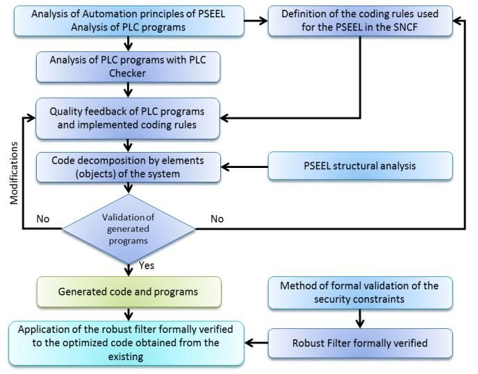
                                                                   The main interest of this standardization approach is the
Feeder, Common …) (Fig. 4), a first view of the subassembly
                                                                   automatic PLC code generation. Fig. 5 shows the steps of this
PSEEL can be done. This view is used to distribute the
                                                                   approach which will be detailed in this article.
system control. This division is used to distribute the
components of each deliverable by sSys. Then each sSys can
be decomposed into Elements of the System (ElSys) (Circuit
Breaker, Switch …), which correspond to "objects" of the
system (Fig. 4). Each object can then be associated with
different deliverables components.
Thus it is possible to reconstruct the project deliverables from
a description of the system containing the sSys itself
compound of ElSys. The detailed description can then
generate all deliverables following the existing project
workflow. This unique description will focus the attention of
the systems engineer and optimize the curve of his mental
workload. The configurable description increases safety in
the project generation process. Indeed, during the description,
a consistency check is made to prevent inconsistent data
entering. The information is then visible by the systems
engineer so that he can correct his own error. The consistency
check is based on the relational database model of the system
corresponding to the object model.                                 Fig. 5. Decomposition of the Standardization approach.
                                                                   Before implementation, it is necessary to define requirements
                                                                   through a specification. Fig. 5 seen above shows the object
                                                                   oriented aspect of our generation process. To build the
                                                                   generation model, input data are necessary:
                                                                   - “Who?” Who are the objects that will make up the model?
                                                                   - “What?” What function (attributes and services) the object
                                                                   will provide?
                                                                   - “Where?” Where will the object be controlled as the system
                                                                   is distributed ? (which PLC?)
Fig. 4. Object modeling of a PSEEL (system decomposition).         - “How?” How to organize the final model in a coherent
                                                                   way?
4.2 Generation of deliverables around mental workload
                                                                   To answer these questions, an analysis phase of the programs
Generation of deliverables from the unique description made        and systems principles is necessary. From this analysis, the
by the systems engineer requires a second reading. This            standardization process starts with a normalization phase of

                                                              12130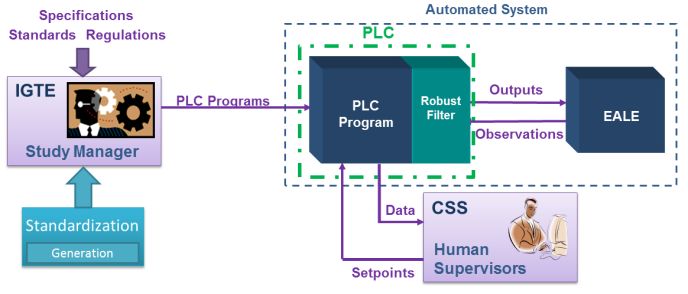
19th IFAC World Congress
Cape Town, South Africa. August 24-29, 2014
the computing rules used by the SNCF. It is then necessary to 5. SAFETY BY ROBUST FILTER OF CONSTRAINTS
use the object modeling of the system to assign the
In the approach described in Fig. 5 the last step is to add a
standardized code to each ElSys. Normalization is done from
safety layer with a filter of Boolean constraints formally
the expertise and feedback from studies and analysis
verified by using a model-checker. The quality and the rigor
programs made with PLC Checker1 . This tool automatically
of control-command synthesis realized by a systems engineer
analyzes PLC programs and verifies, in an exhaustive way,
depend only on his/her skills and experiences. System safety
their conformity with generic rules (ISO 9126). The use of
is ensured by the robust filter regardless of the implemented
this tool allows IGTE to assure the respect of the generic
control-command. Indeed, ensuring a formal safety to
computing rules but also of the specific rules of Electric
automated systems is a scientific challenge that issues
Traction field. Indeed, it is possible to define additional
important industrial stakes. The interest of the robust filter is
specific rules to verify the consistency of the programs.
to insure systems engineer that he/she will not interfere with
To generate a quality PLC code, it is necessary to harmonize system and human safety. So he/she can be serene and it
the programs before, to have typical programs. These typical avoids a state of stress which can lead to a mental overload.
programs are based on the principles of automation described
A methodology has been described by (Marangé et al., 2010)
by IGTE. The process of standardization is thus ideal to
to get a robust filter formed by a set of safety constraints
harmonize the programs and improve their quality. It is then
formally verified from a Failure Modes and Effects Analysis
necessary to break up the system starting from the structural
(FMEA) of the system. This check is done through the
analysis of the system in order to assign the standardized
model-checker UPPAAL (Behrmann et al., 2002), allowing
code to each ElSys. As we explained through the fig. 4, each
the system modeling and formal verification of system
ElSys is part of a sSys. The system being distributed, each
properties and of proposed logical constraints (Fig. 6). Safety
sSys is controlled by a PLC, in order to ensure the greater
constraints are expressed as a monomial (product of logical
system reliability and availability. Thus the ElSys, children of
a same sSys are controlled by the same PLC. For example, variables, form) which is a logical function of the inputs /
two sSys insuring the same function are controlled by two outputs of the PLC and any possible observers (function of
dedicated PLC. Their ElSys are controlled by a PLC inputs) to compensate the lack of observability of the system.
dedicated to the parent sSys. So if one of the sSys breaks
down, the other still ensures the functionality by redundancy.
The generated programs can be divided into three steps:
1. Beginning PLC cycle:
o Initialization of the variables,
o Reading of the inputs state,
o Reading of the variables on the network,
o Observers construction,
2. Control programs of the devices:
o Sequential control of the devices,
o Checking of the orders coherence,
3. End PLC cycle:
o Writing of the variables on the network,
o Writing of the outputs.
Fig. 6. Safety command filter synthesis.
The programs of steps 1 and 3 are attached to the PLC in
charge of a sSys, they follow a standardized structure and are The robust filter is implemented at the end of the control-
generated according to the sSys and ElSys children types. On command program in the PLC. It is then possible to verify
the contrary the step 2 programs are only related to the ElSys formally if the set of safety constraint is necessary and
controlled by the PLC. enough to ensure the system safety thanks to UPPAAL. The
devices command model and the system evolution model are
From the standard code assigned to elements of the PSEEL, it not enough to simulate the system. It is necessary to define
is possible to generate the PLC code. It is then necessary to the system model and the PLC cycle model. The PLC Cycle
check the validity of the generated code and its quality. If the Model (Fig. 7) is decomposed in ordered sub tasks.
code is validated, then the tool can be used by the systems
engineers to design PSEEL.
Finally, the last phase of the approach is the implementation
of the robust filter based on safety constraints on the same
principle of affectation and decomposition according to the
structure of the PSEEL.
1
www.automationsquare.com/plc-checker.html Fig. 7. PLC Cycle Model with Uppaal.
12131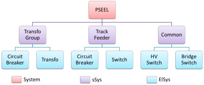
19th IFAC World Congress
Cape Town, South Africa. August 24-29, 2014

Although this formal approach requires the intervention of an        construction and memorization, the robust filter operates to
expert of the system, combined with the standardization              verify that the proposed PLC outputs are not going to violate
process, it allows to strengthen the safety of the elements of       any safety constraints. If a safety constraint would be
the system without complicating the work of systems                  violated, the default output would be changed to stay in the
engineers. This work of elementary decomposition of the              system safety space of functioning. When the set of
safety constraints must not evolve. Only the functional part of      constraints is respected, outputs are written and the system
elements may need to be modified. The safety part must be            model is updated to take into the account the new position of
the same in anytime. That is why the interest to insure the          ElSys after one PLC cycle in order that the system model
safety of the ElSys and of the global system, thanks to the          evolving is considerate by the next inputs reading.
formal filter, whatever is the implemented command in the
                                                                     The PLC cycle is decomposed to obtain a model that is the
PLC seems obvious.
                                                                     nearest from the system reality. The devices command model
                  6. APPLICATION ON PSEEL                            (Fig. 8) has been defined with the possibility of one transition
                                                                     by PLC cycle.
One of our proposals is to define the constraints not from the
FMEA but from the testing procedures book. As we said
before, verification and validation of the system and
programs correct operation are ensured by the testing
procedures book. Those tests are realized on each PSEEL of
the French territory. We assume that it is not a formal
definition way. Nevertheless this set of safety constraints, if it
is well written, ensures that the testing procedures book will
be respected and passed. The tests phases are not formal but
it has the interest of the experience feedback. Indeed, after
dozens years of operation, the PSEEL safety has always been
ensured. The experience feedback is the first thing to take in
the account, establishing the set of constraints from the
testing procedures book and so on the experience feedback,
permit to ensure the safety rules already defined by the
SNCF.                                                                Fig. 8. Switch Command Model with Uppaal.
For example, in a Transformer Groupe (TG), the HV Switch             The devices state model includes a transition state during
(HVS) must not be closed if the TG Circuit Breaker (TGCB)            which the device position is not known (Fig 9): so = sc = 0.
is not open. The HVS must not be opened if the TG Circuit            The opening and closing movement are considerate as
Breaker (TGCB) is not open.                                          courses during PLC cycle.
That can be written2:
(CSS1) CCHVS . NOT(soTGCB) = 0
(CSS2) OCHVS . NOT(soTGCB) = 0
On the contrary, the Snap Action Switch (SAS) of the TG can
be opened in charge, so no constraints are applied. But the
SAS must not be opened if the TGCB is not open. That can             Fig. 9. Switch Evolution Model with Uppaal.
be written:                                                          The implementation of those models under Uppaal allows the
(CSS3) OCSAS . NOT(soTGCB) = 0                                       formal verification of the properties which must be respected
                                                                     by the system. To verify the properties, Uppaal uses the CTL
With those three constraints the filter ensures that no              logic (Clarke, E. et al. 1986) and try to find a way showing
erroneous command or order can be sent either to the HVS or          that properties are not verified. If the system safety is
to the SAS.                                                          ensured, then the robust filter can be implemented at the end
During the PLC first cycle, an initialization step is necessary      of the PLC cycle.
to configure the studied system. After this configuration step,                           7. CONCLUSIONS
the normal cycle starts with the reading of the system
information by the PLC inputs. The command models are                The process of standardization and safety presented in this
then able to evolve and the PLC outputs are updated with the         article demonstrates an interest at several levels of the life
new command defined. After this commands, observers are              cycle of a PSEEL.
constructed, in particular inputs and outputs rising edge and        Indeed, during the design phase (Fig. 10a), the automatic
falling edge which are very useful. After the observers’             generation avoids repetitive tasks due to the data entering of
                                                                     redundant information. The solution of generation allows to
2
    OC: opening command           CC : closing command               focus the concentration of the systems engineers on the
    so : signal of opened state   sc: signal of closed state         cognitive tasks and so to avoid mental underload. The
                                                                     standardization approach also prevents mental overload, due

                                                                12132
19th IFAC World Congress
Cape Town, South Africa. August 24-29, 2014
to the proliferation of computing supports, by integrating a Symposium on Analysis, Design, and Evaluation of
software environment based on a unique data entering. Human-Machine Systems (HMS 2013), Las Vegas.
EN 50126. Applications ferroviaires - Spécification et
The robust filter can inhibit command errors of an operator.
démonstration de la fiabilité, de la disponibilité, de la
The sending of an erroneous command will be filtered by the
maintenabilité et de la sécurité (FDMS) (2000).
safety constraints implemented in the robust filter. This kind
IEC 60848. Specification language GRAFCET for sequential
of error can occur when the operator is mentally overloaded,
function charts Ed. 2 (1999).
in case of simultaneous incidents. This additional safety helps
IEC 61131-3. Programmable controllers - Part 3:
to decrease the stress suffered by the operator due to the
Programming languages Ed. 2 (2003).
decision-making in a limited time (Fig. 10b). The inhibition
ISO 9126. Software engineering-Product quality Ed.2 (2001).
of a command sent by the operator will have the effect of
ISO 10075. Principes ergonomiques concernant la charge de
awakening the human supervisor vigilance. This effect can be
travail mental -- Termes généraux et leurs définitions
beneficial when the human supervisor undergoes an overload
(1991).
peak after mental underload phase due to the waiting for an
Lancry, A., and Lammens, J.M. (1998). Étude différentielle
event.
des fluctuations de performances à une tâche complexe
au cours de la journée. Le Travail Humain, 61 (2), 153-
169.
Marangé P., Benlorhfar R., Gellot F., Riera B., 2010.
Prevention of human control errors by robust filter for
manufacturing system, 11th IFAC Symposium on
Analysis, Design, and Evaluation of Human-Machine
Systems (HMS 10), France.
Fig. 10. Influence of various benefits on PSEEL life cycle. Millot, P. (1987) Coopération homme-machine dans les
tâches de supervision des procédés automatisés. Thèse de
Track development of the approach is the implementation of doctorat, Université de Valenciennes.
a feedback to the CSS when a safety constraint is violated. Riera, B., Philippot, A., Annebicque, D., Gellot, F. (2012). 8th
This feedback would allow meaningful interaction between Symposium on Fault Detection, Supervision and Safety
the human supervisor and the robust filter. Nevertheless, this of Technical Processes (SAFEPROCESS 2012), Mexico.
solution cannot be applied at the moment for technical Sargent, L.D. and Terry, D.J. (2000). The moderating role of
reasons. It is currently not possible to measure the actual social support in Karasek’s job strain model. Work and
effect of our approach on the life cycle of the PSEEL. To Stress, Vol. 14, No. 3, pp. 245-261.
bring these results, it is necessary to have an experience Sperandio, J.C. (1988). Ergonomie du travail mental. Paris.
feedback over a significant duration to be able to compare Stanton, N. A., Young, M., and McCaulder, B. (1997). Drive-
with existing systems. by-wire: The case of driver workload and reclaiming
control with adaptive cruise control. Safety Science,
ACKNOWLEDGEMENTS 27(2/3).
The authors thankfully acknowledge the support and the UTE C 18510. Operations on electrical work and installations
interest from SNCF. We are indebted to PSIGT-TE members and in an electrical environment - Electrical hazard
for their strong experience in PSEEL work. prevention.
Wickens, C. D. (1984). Processing resources in attention.
REFERENCES Varieties of attention (pp. 63-101). New York: Academic
Askenazy, P., and Caroli, E. (2003). Pratiques innovantes, Press.
accidents du travail et charge mentale: résultats de Young, M. S. and Stanton, N. A. (2001). Mental workload:
l’enquête française sur les Conditions de travail. Pistes, 1 theory, measurement, and application. In W. Karwowski
(5), 1-30. (Ed.), International encyclopedia of ergonomics and
Behrmann G., Bengtsson J., David A., Larsen K.G., human factors: Vol. 1, pp.507-509. London: Taylor and
Pettersson P., Yi W., (2002). Uppaal implementation Francis.
secrets. 7th International Symposium on Formal
Techniques in Real-Time and Fault Tolerant Systems.
Springer-Verlag London, UK 2002: 3-22.
Clarke, E. M., Emerson, E. A., and Sistla, A. P. (1986).
"Automatic verification of finite-state concurrent
systems using temporal logic specifications". ACM
Transactions on Programming Languages and Systems 8
(2): 244–263.
Coupat, R., Meslay, M., Burette, M. A., Philippot, A.,
Annebicque, D., Riera, B., (2013). Standardized
generation and Robust filtering for optimization of the
mental workload of the systems engineer. 12th IFAC
12133You can also read


