VIKING KETTLE Installation and Operation Manual - VIKING MARINE - Metos
←
→
Page content transcription
If your browser does not render page correctly, please read the page content below
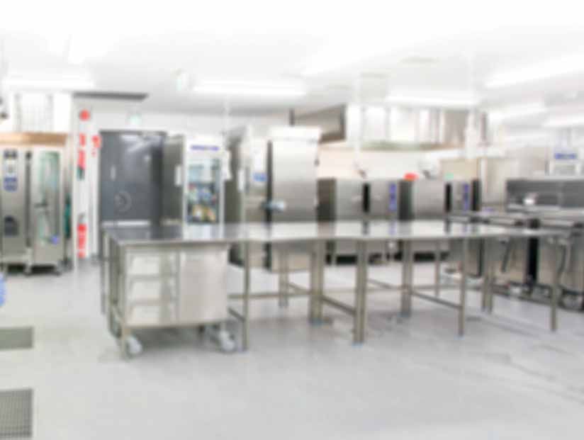
VIKING KETTLE
                 VIKING MARINE

             ELECTRICALLY HEATED
        40E SW, 60E SW, 80 ESW, 100 ESW

Installation and Operation Manual
                      Original instructions

                           Rev 1.1
                          (26.3.2018)
           S/N: 1091 090210010 Valid from 21.09.2009

             4215815, 4215816, 4215817, 4215819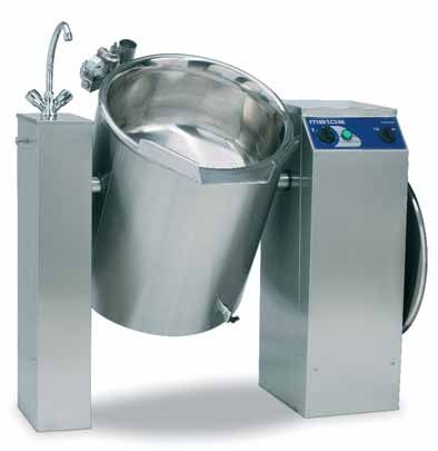
VIKING MARINE                                                              26.3.2018                   Rev. 1.1

     TABLE OF CONTENTS
        1.       General .......................................................................................................................................................5
        1.1.     Symbols used in the manual .......................................................................................................................5
        1.1.     Symbols used on the appliance...................................................................................................................5
        1.1.     Checking the relationship of the appliance and the manual ........................................................................6
        2.       Safety .........................................................................................................................................................7
        2.1.     Safety features ............................................................................................................................................7
        2.2.     Warnings .....................................................................................................................................................8
        3.       Functional description ..............................................................................................................................9
        3.1.     Operating principle ......................................................................................................................................9
        3.2.     Construction and control panel.................................................................................................................. 10
        3.2.1.   Control panel ............................................................................................................................................. 10
        4.       Operating instructions ............................................................................................................................ 11
        4.1.     Before use ................................................................................................................................................. 11
        4.1.1.   After the installation .................................................................................................................................. 11
        4.1.2.   Before the first use.................................................................................................................................... 11
        4.1.3.   Daily........................................................................................................................................................... 11
        4.1.4.   Quarterly.................................................................................................................................................... 11
        4.1.5.   Yearly .........................................................................................................................................................12
        4.1.6.   Checking the water level of the steam generator .....................................................................................12
        4.1.7.   Total emptying of the steam generator ....................................................................................................13
        4.2.     Operation...................................................................................................................................................13
        4.2.1.   Cooking .....................................................................................................................................................13
        4.2.2.   Tilting the kettle .........................................................................................................................................14
        4.2.3.   Filling water into the kettle ........................................................................................................................14
        4.3.     After use ....................................................................................................................................................15
        4.3.1.   Cleaning the kettle.....................................................................................................................................15
        4.3.2.   Treatment of stainless steel ......................................................................................................................16
        4.3.3.   Notes on service work ..............................................................................................................................17
        5.       Installation ...............................................................................................................................................19
        5.1.     Before use .................................................................................................................................................19
        5.1.1.   Transport and reception .............................................................................................................................19
        5.1.2.   Storage ......................................................................................................................................................19
        5.1.3.   Facilities.....................................................................................................................................................19
        5.1.4.   Unpacking the unit.....................................................................................................................................19
        5.1.5.   Industrial safety during installation ............................................................................................................20
        5.2.     Installation .................................................................................................................................................20
        5.2.1.   Installation on subsurface frames cast into the floor ................................................................................20
        5.2.2.   Installation on surface installation frames .................................................................................................21
        5.3.     Electrical and water connections...............................................................................................................21
        5.3.1.   Electrical connection .................................................................................................................................21
        5.3.2.   Water connection ......................................................................................................................................22
        5.4.     Ventilation ..................................................................................................................................................22

2|
VIKING MARINE                                                           26.3.2018                  Rev. 1.1

5.5.     Adjusting the tilting ...................................................................................................................................23
5.6.     Testing the kettle .......................................................................................................................................24
5.6.1.   Filling the steam generator........................................................................................................................24
5.6.2.   Preventing the scale build-up ....................................................................................................................25
5.6.3.   Checking the safety valve ..........................................................................................................................25
6.       Troubleshooting.......................................................................................................................................27
7.       Spareparts ................................................................................................................................................29
7.1.     Voltage Codes ...........................................................................................................................................31
7.2.     Product codes ...........................................................................................................................................31
8.       Technical specifications ..........................................................................................................................48

                                                                                                                                                                                    |3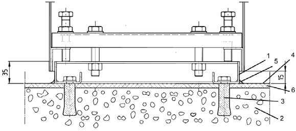
VIKING MARINE   26.3.2018   Rev. 1.1

4|
General                                             VIKING MARINE                                    26.3.2018          Rev. 1.1

1.        General
                     Carefully read the instructions in this manual as they contain important information regarding proper,
                     efficient and safe installation, use and maintenance of the appliance.

                     Keep this manual in a safe place for eventual use by other operators of the appliance.

                     The installation of this appliance must be carried out in accordance with the manufacturer’s instructions
                     and following local regulations. The connection of the appliance to the electric, steam and water supply
                     must be carried out by qualified persons only.

                     Persons using this appliance should be specifically trained in its operation.

                     Switch off the appliance in the case of failure or malfunction. The periodical function checks requested in
                     the manual must be carried out according to the instructions. Have the appliance serviced by a technical-
                     ly qualified person authorized by the manufacturer and using original spare parts.

                     Not complying with the above may put the safety of the appliance in danger.

1.1.      Symbols used in the manual
                     This symbol informs about a situation where a safety risk might be at hand. Given instructions are man-
                     datory in order to prevent injury.

                     This symbol informs about the right way to perform in order to prevent bad results, appliance damage
                     or hazardous situations.

                     This symbol informs about recommendations and hints that help to get the best performance out of the
                     appliance.

1.1.      Symbols used on the appliance
                     This symbol on a part informs about electrical terminals behind the part. The removal of the part must be
                     carried out by qualified persons only.

                                                                                                                                   |5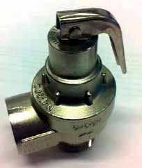
General                                             VIKING MARINE                                    26.3.2018          Rev. 1.1

     1.1.      Checking the relationship of the appliance and the manual
                          The rating plate of the appliance indicates the serial number of the appliance. If the manuals are missing,
                          it is possible to order new ones from the manufacturer or the local representative. When ordering new
                          manuals it is essential to quote the serial number shown on the rating plate.

                          If language versions have information contradictions, the original language English is the primary langu-
                          age regarding the information content.

                          This manual covers the following Viking kettles and all their options:

                          • electrically heated Viking Marine kettles 40, 60, 80 and 100 with separate water faucet SW

6|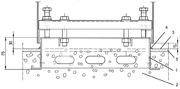
Safety VIKING MARINE 26.3.2018 Rev. 1.1
2. Safety
2.1. Safety features
The kettle is built for 1,5 bar pressure, and the working pressure is 1,0 bar. The working height is 900 mm.
The double steam jacket is isolated with a third casing jacket, throughout equipped with a foil and foam
insulation, which limits the top temperature of the outer steam jacket under the skin burn limit. The kettle
can be cleaned with a cleaning hose (IPX5). Water jets directed towards the vent holes and control panel
from a near distance should be avoided.
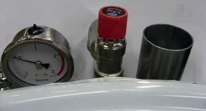
The kettle is fitted with many different safety devices to ensure smooth and safe operation. The safety
equipment at the rim behind the kettle includes a pressure gauge, a safety valve and an automatic va-
cuum valve. The safety valve opens if the steam pressure exceeds 1,5 bar.
In addition to the safety valve, the kettle has a pressure switch which operates as a backup safety device
of the safety valve. The control does not allow the steam jacket temperature to exceed 120°C. This tem-
perature corresponds to a 1,0 bar steam pressure.
The water level probe in the steam generator operates as a boil dry protector. In case of insufficient water
level in the steam generator the heating element power is cut off until water is added to the kettle jacket.
In addition, a limit switch which is attached to the tilting axle turns off the heating during tilting.
|7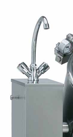
Safety                                        VIKING MARINE                                    26.3.2018          Rev. 1.1

     2.2. Warnings
                     Please take careful note of the following instructions and warnings. Further on in this manual, there are
                     warnings which are to be noted in special operation situations. To prevent damage and accidents, please
                     read the whole manual before attempting to operate the appliance.

                     • Viking kettles are to be used only for food preparation. Interacting or corrosive substances are not to
                       be prepared in the kettle. Note that also long-term effect of some food preparation substances, such
                       as salt, acetic acid, lemon acid and lactic acid, can be corrosive.
                     • To prevent burns, do not during the use touch the inner surface and lid. Do not put your hands, without
                       appropriate protection, above the kettle while cooking.
                     • Beware of hot steam when removing the lid.
                     • Do not open the control valve of the steam generator, the safety valve or the water inlet valve when
                       there is pressure in the steam jacket. Releasing hot steam might cause burns.
                     • Do not stand behind the kettle during tilting.
                     • After using the kettle, clean it according to the cleaning instructions given in this manual to keep the
                       high hygiene level.
                     • It is forbidden to use the kettle without cover plates or if the cover plates are not properly fitted.
                     • Beware of sharp edges on the sheet construction inside the kettle pillars during installation and ser-
                       vice work.
                     • The following danger of electrical shock mark is fitted on cover plates protecting electrical compo-
                       nents from being touched which would cause danger to life.

                     The manufacturer will not take responsibility for potential damage caused to units or persons if the given
                     instructions have not been followed.

8|
Functional description                                  VIKING MARINE                                      26.3.2018            Rev. 1.1

3.      Functional description

3.1. Operating principle
                         The Viking kettle is heated by steam generated with heating elements. The steam generator is situated
                         below the kettle. The steam jacket reaches the upper edge of the kettle. The cooking procedure is regu-
                         lated with a stepless power regulator. The kettle tilts by means of a tilting motor. The inner surface of the
                         kettle and the jacket are acid proof stainless steel (EN 1.4432). All other construction is of stainless steel
                         (EN 1.4301). The kettle is provided with a third jacket and it is throughout thermally isolated.

                         The corrosion resistance of stainless steel is due to a so called passive layer, which is a very thin chro-
                         mium oxide film. This film is naturally and fairly quickly formed on the stainless steel surface when the
                         surface is in contact with oxygen (air). The chromium oxide film is hard, but in some situations it is pos-
                         sible to damage it with hard materials. When using steel tools, there is a potential risk of scratching the
                         inner jacket and hence increased risk of corrosion. Therefore, we recommend using wooden or plastic
                         tools in the kettle, especially when mixing and scraping.

                         The control panel of the kettle is on the control pillar and the water faucet on the support pillar.

                                                                                                                                           |9
Functional description VIKING MARINE 26.3.2018 Rev. 1.1
3.2. Construction and control panel
The main features of the Viking kettle are described in the following pictures.
1
7
3
6
2
5
4
8
1. safety
t block
blockk
2. lid
3. control panel
4. control pillar
5. support pillar
6. peg for hanging tools
7. water faucet
8. control valve of steem generator
3.2.1. Control panel
The control panel and its functions are described in the following picture.
3 1 2
1. green indicator light ”kettle ON”
2. tilting switch
3. power regulator
10 |Operation instructions VIKING MARINE 26.3.2018 Rev. 1.1
4. Operating instructions
4.1. Before use
Check the following points before using the kettle.
4.1.1. After the installation
Check that
• the kettle has been installed horizontally according to the installation instructions
• all connections (electricity and water) are tight and correctly made .
4.1.2. Before the first use
Clean the kettle thoroughly with warm detergent solution and remove the dust and dirt with a cloth. Dry
all surfaces after cleaning.
4.1.3. Daily
Check that
• the kettle is in its upright and horizontal position. The kettle does not heat if it is tilted.
• the steam generator has the right amount of water (normally water must be refilled a few times per year).
4.1.4. Quarterly
1,0 bar 1
1. Do the checking when the kettle is empty.
2. Check the water level of the steam generator.
3. Switch the kettle on by turning the power regulator to position 6.
4. Heat up the kettle until the pressure gauge shows 1,0 bar
pressure.
5. Open the safety valve by cautiously lifting the relief lever (1)
upwards. Now the safety valve should open and the pressure
gauge should indicate a lower value.
Beware of hot steam. 1 safety valve relief lever
2014 -> 1,0 bar 1
1. Do the checking when the kettle is empty.
2. Check the water level of the steam generator.
3. Switch the kettle on by turning the power regulator to position 6.
4. Heat up the kettle until the pressure gauge shows 1,0 bar
pressure.
5. Open the safety valve by cautiously turning the relief knob (1) in
the direction of the arrow on the nob. Now the safety valve should
open and the pressure gauge should indicate a lower value.
Beware of hot steam.
1 safety valve relief knob
| 11Operation instructions VIKING MARINE 26.3.2018 Rev. 1.1
4.1.5. Yearly
• It is advisable to have the unit checked once a year by qualified personnel. Preventive checking is the
best guarantee for operational reliability and saves breakdown costs.
• Depending on the hardness of water, descaling must be done by qualified personnel. When doing the
first descaling the technician can estimate when the following descaling must be done.
Fill out the form “Notes on service work” with information on service work which has been done accor-
ding to the instructions. Maintenance work ensures the safe and reliable function of the kettle.
4.1.6. Checking the water level of the steam generator
It is not allowed to open the control valve of the steam generator if the temperature of the steam jacket
of the kettle is over +100°C. Watch out for releasing hot steam and water when you open the above
mentioned valves.
1
1 control valve of steam generator
• Check that the kettle is in its upright position.
1 water inlet funnel
1
2 handle of the water inlet valve
2
• Open the water inlet valve, which is under the water inlet funnel, by turning the handle (2) parallel to
the valve.
• Let water into the water inlet funnel. Stop filling water when water starts to drop out of the control valve.
• Close the water inlet valve. Close the control valve when water has stopped running out of it.
The kettle does not heat if there is not enough water in the steam generator. Add water if needed accor-
ding to the instructions.
12 |Operation instructions VIKING MARINE 26.3.2018 Rev. 1.1
4.1.7. Total emptying of the steam generator
It is not allowed to open the control valve of the steam generator if the temperature of the steam jacket
of the kettle is over +100°C. Watch out for releasing hot steam and water when you open the above
mentioned valves.
1. Open the control valve.
2. Tilt the kettle approximately 45°.
3. When water stops to flow out, tilt the kettle slightly forwards and backwards until water no longer
flows out.
4. Return the kettle to the cooking position.
5. Close the control valve.
4.2. Operation
4.2.1. Cooking
Starting to cook
• Check that the kettle is in the fully uppright position
• Switch on the power by turning the power regulator to the right (green signal lamp illuminates). If the
kettle does not start to heat up, check the water level of the steam generator according to instructions
given in Chapter “Checking the water level of the steam generator”.
1 2
1. power regulator
2. green light indicator ”kettle ON”
Keep the valve of the water inlet funnel open until steam starts to come out of it. Then close the the
inlet funnel valve. This procedure ensures that air is eliminated from the steam jacket and the cooking
is efficient
Stopping the cooking
Turn the power regulator to the left to position 0. The green indicator light goes off and the kettle stops
cooking.
The cooking will automatically stop when the kettle is tilted. The cooking goes on automatically when the
kettle is returned to an upright position.
| 13Operation instructions VIKING MARINE 26.3.2018 Rev. 1.1
4.2.2. Tilting the kettle
Remove the lid of the kettle before tilting and ensure that there is enough space for tilting behind the
kettle.
1 2
The kettle is emptied by turning the tilting
switch to the left to position (1).
The kettle goes back to its upright/cooking
position by turning the tilting switch to the
right to position (2).
For security reasons, the kettle tilts only when the tilting switch is continuously held turned.
4.2.3. Filling water into the kettle
A cold and hot water faucet is situated on the left hand support pillar. Only cold water should be used
for food preparation.
14 |Operation instructions VIKING MARINE 26.3.2018 Rev. 1.1
4.3. After use
4.3.1. Cleaning the kettle
Use of a high pressure hose for cleaning of the kettle is forbidden.
Note that it is not allowed to spray the air inlets or the control panel with water when cleaning the kettle
with a spray gun.
Always clean the unit carefully, considering the hygienic aspects, immediately after use. Cleaning is more
easy to do and needs less water in this way.
Recommended tools for cleaning:
• special cleaning detergents for stainless steel
• nylon brush
• soft rubbing sponge (white)
• other materials meant for stainless steel which do not scratch the surfaces of the kettle
Tools not allowed for cleaning:
• high pressure hose
• all metallic tools
• rough rubbing sponge (green)
• steel wool
• abrasive detergents
Cleaning procedure:
1. Chill the kettle with cold water
2. Scrape the dirt with a plastic scraper.
3. Spray detergent in the kettle, brush and wash clean with a water hose
4. Dry the kettle
Clean the outer parts of the kettle using running water only if necessary. Do not use water more than is
necessary. Cleaning with a damp cloth will often be enough.
All optional extras of the kettle such as strainer plates, cooking baskets and the lid can be washed in a
dishwasher.
The dosing and impact time instructions for cleaning detergents must be followed - e.g. exceeding the
impact time for foam cleaning detergents in combination with salt residues has been observed to cause
severe spot corrosion even on stainless steel.
The manufacturer does not take any responsibility for possible damage caused by not following the
instructions above.
| 15Operation instructions VIKING MARINE 26.3.2018 Rev. 1.1
4.3.2. Treatment of stainless steel
The following table contains the most typical problems encountered in the treatment of stainless steel
and their solutions.
Note that some substances mentioned in the table can damage the stainless steel surface if they are
used too long or they are too strong. Therefore, the instructions given in the schedule must be strictly
followed.
Effect Cause How to avoid/remove
Little white spots on the bottom Salt has been added to cold wa- Add salt always into boiling water or when the food is
of the kettle ter. ready. Clean with acetic solution (0,5 dl vinegar/1 l wa-
ter), heat appr. 1/2 hours, brush and rinse.
Grey-white blotches and spots, Hard water containing calcium Clean with acetic solution (1 dl vinegar/1 l water), heat
calcareous deposits and magnesium salts. approx. 1/2 hours, brush and rinse.
Brown spots Dirt from food ingredients, steel Clean with acetic or alkaline solution according to the
particles coming from outside. cause.
”Rainbow colours” Sudden temperature change. Totally harmless, disappears in use.
Tightly stuck food Too high cooking temperature. Soak water in the kettle and cook diluted alkaline solution
according to instructions given with the detergent. Redu-
ce cooking temperature.
Blue coating Substances containing carbo- Sometimes hard to remove. Soak water in the kettle and
hydrate or old coffee and tea cook diluted alkaline solution according to instructions
spots. given with the detergent.
Firmly adhered label or sellotape Adhesive from labels or sellota- Rub the adhesive with a cloth dipped in cooking oil. Do
pe not scratch the surface.
16 |Operation instructions VIKING MARINE 26.3.2018 Rev. 1.1
4.3.3. Notes on service work
Kettle/kettle group___________________________ Date of installation_________________________________
Checking the safety valve four times per year:
Date Checked by Notes Date Checked by Notes
Yearly maintenance:
Date Checked by Notes Date Checked by Notes
Descaling:
Date Checked by Notes Date Checked by Notes
| 17Operation instructions VIKING MARINE 26.3.2018 Rev. 1.1 18 |
Installation                                        VIKING MARINE                                       26.3.2018          Rev. 1.1

5.       Installation

5.1. Before use
                    Please observe the following instructions and warnings when planning and carrying out the transport and
                    installation of the kettle in order to reduce the risk of damage, failure or injury. This applies to forwarders,
                    transport personnel, installation professionals and end-users alike. Not following the instructions might
                    cause damage to the units and personnel.

5.1.1. Transport and reception

                    The unit must be transported in its own package to avoid transport damage. It is forbidden to load any
                    heavy packages on the unit during transport and storage.

                    The unit is not stable until bolted down to the floor. For this reason it is imperative not to operate or tilt
                    the kettle until it is bolted down according to the installation instructions. When the kettle is removed
                    from its transport pallet, it must be supported to prevent it from falling over before it is fixed to the floor.
                    If the kettle falls down, this may cause damage to the unit and put personnel at risk.

                    The consignee of the kettle must check the unit immediately after transport and, if any damage is de-
                    tected, it must be noted on the bill of freight. If this is neglected, all transport damage detected later on
                    (except those covered by normal product guarantee) will be repaired at the customer’s cost.

5.1.2. Storage

                    The unit must be stored in a dry place where the temperature is between + 0° and 40°C. The unit must
                    remain in its own package during storage.

                    If the unit is stored on a construction site, special care must be taken not to damage the unit when car-
                    rying out other construction work.

                    • Protect the outer surfaces of the unit from scratches and knocks.
                    • Protect the unit from construction site dust.
                    • Protect the unit from welding, grinding and abrasive cutting wheel sparks. These might later cause
                      rust spots on the stainless steel surfaces of the unit.

5.1.3. Facilities

                    The kettle can be used in a normal, air-conditioned professional kitchen. The room temperature of the
                    installation place must not exceed +40°C and the relative humidity must be less than 80% (condensation
                    on surfaces not allowed to occur). If the temperature of the facility in winter conditions is below 0°C, the
                    steam generator of the kettle must be drained and the kettle must be emptied to avoid damage caused
                    by freezing. The kettle’s pipes and solenoid valve bodies must be emptied at the same time.

5.1.4. Unpacking the unit

                    The kettle is transported in its own package as near the installation place as possible before final un-
                    packing. Remove the plastic foil wrapped round the kettle after the installation just before the first use
                    of the kettle.When unpacking all packing material must be sorted and disposed of according to local
                    recycling regulations.

                                                                                                                                       | 19
Installation VIKING MARINE 26.3.2018 Rev. 1.1
5.1.5. Industrial safety during installation
Beware of sharp edges of sheet constructions in the kettle pillars when installing the unit.
Do not switch the power on, if the unit’s installation area is wet or moist.
5.2. Installation
Check before installation from the installation drawing that there is enough space behind the kettle for
tilting. Check also the location of the floor drain.
The kettle can be installed in the following two ways:
• on subsurface installation frames, frames cast into the floor
• on surface installation frames, frames fixed between the kettle and the floor
Remove the front panels of the control pillar and support pillar when installing. It is recommended to put
wooden slats below the kettle axles when raising the unit during the installation to avoid possible falling
of the kettle. If you are installing a kettle group, first separate the kettles. Begin the installation with the
left-hand kettle and do not forget to support the right-hand kettle after removal from the left-hand tem-
porary support.
5.2.1. Installation on subsurface frames cast into the floor
The optional subsurface installation frame is to be correctly positioned before casting. The frame should
be installed in a horizontal position and fixed so that it will not move during the casting. The top of the
installation frame must be approx. 30 mm above the finished floor surface. The junction between the
floor and the frame is to be covered with flooring material up to the level of the installation frame as
shown in the picture below.
1. Installation frame
2. Concrete casting
3. Finished floor surface
4. Silicone mastic
5. Acrylic filler
Place the kettle on the installation frame and adjust to a horizontal position with the adjusting bolts
which are in the corners of the pillars. When the kettle is in a horizontal position, it must be fixed to the
installation frames with the help of M12 fixing bolts. The control pillar has 4 bolts and the support pillar
has 2 bolts. Tighten the adjusting nuts carefully. Do not seal the space between the kettle pillars and
installation frame as there must be enough change of air.
20 |Installation VIKING MARINE 26.3.2018 Rev. 1.1
5.2.2. Installation on surface installation frames
The optional installation frame is to be installed according to the installation drawing. If the floor is not
even, it might be necessary to straighten the installation frame to a position nearer to the horizontal by
putting some stainless steel spacers between the frame and the floor, so that the adjustment range of
the pillar is sufficient.
The junction between the installation frame and the floor is sealed with silicone or similar.
1. Surface frame
2. Concrete casting
3. Fixing bolt for surface frame
4. Finished floor surface
5. Silicone mastic
6. Acrylic filler
Fixing bolts of the surface installation must be chosen according to the floor material. Recommended
type is a UKA 12x200 chemical bolt, which is suitable for different floor materials. Alternatively expansi-
on-shell bolts or equivalent can be used.
Place the kettle on the surface installation frame and adjust to a horizontal position with 4 adjusting bolts
which are in the corners of the pillars. When the kettle is in a horizontal position it must be fixed to the
surface frame with the help of M12 fixing bolts. The control pillar has 4 bolts and the support pillar has
2 bolts. Tighten the fixing nuts carefully. Do not seal the space between the kettle pillars and surface
installation frames, as there must be enough change of air.
5.3. Electrical and water connections
The electrical connection is made to the right-hand kettle pillar according to the installation drawing.
5.3.1. Electrical connection
Connections are to be done according to the installation drawing and the electric diagram.
The kettle must be equipped with a decoupling switch, which separates the kettle totally from the
electrical network.
| 21Installation VIKING MARINE 26.3.2018 Rev. 1.1
5.3.2. Water connection
The water connection is to be done according to the installation drawing. Connections to the water tap
are to be fitted with one-way and shut-off valves (not included in delivery). The water connection sizes
are Ø 10 mm (G 3/8”).
Quality requirements for water used for filling the steam generator
• Water conductivity should be below 1000µS/cm. Already when the conductivity is over 500µS/cm, a
water analysis is recommended.
• Maximum chloride concentration allowed is less than 60 mg/l.
• Maximum chlorine concentration allowed is less than 0,2 mg/l.
• The pH value of the water should be between 6,5 and 9,5.
• Unit damages caused by chloride, chlorine or pH values exceeding the stated limits are not covered
by manufacturer warranty.
Extreme water conditions
When extreme water conditions not fulfilling the requirements above exist, filters and water treatment
devices should be installed in order to ensure proper water quality for steam generator filling. Specified
water quality is a mandatory requirement for proper function of the unit and for avoidance of corrosion.
When extreme water conditions are at hand, a water quality analysis must be carried out. Depending on
the results of the analysis, needed filters and water treatment devices are installed by the customer. The
most common filters and treatment equipment are:
1. Particle filter
A 5-15µm particle filter is recommended when water contains sand, iron particles or other suspended
matters.
2. Active carbon filter
An active carbon filter must be used if the chlorine level exceeds 0,2 mg/l.
3. Reverse osmosis system
A reverse osmosis system must be used if the chloride concentration exceeds 60 mg/l. This is very cru-
cial in order to avoid corrosion.
4. Water softener
If a high level of scale build-up is experienced, a water softener is needed. H+ Ion Exchanger or
Kleensteam are recommended systems. Sodium ion exchangers must not be used because of problems
caused by high salt content.
5.4. Ventilation
The heat and steam load of the kettle must be taken into account in the kitchen’s ventilation plan. A ven-
tilation hood must be installed above the kettle, because plenty of steam is released when the kettle lid
is opened. When dimensioning the ventilation hood, the space requirement for opening the lid must be
taken into account (see installation drawing).
22 |Installation VIKING MARINE 26.3.2018 Rev. 1.1
5.5. Adjusting the tilting
Ensure that the kettle pillars are in a horizontal position. If not, adjust according to the installation instruc-
tions. Ensure that the rim of the kettle also is horizontal. If not, adjust the tilting as follows.
The adjustment is done from the lower mounting point of the tilting motor as follows:
1. Open the upper locking nut.
2. Adjust the position with the lower nut.
3. Tighten the upper nut.
1. adjustable lower mounts
2. locking nuts
4. Finally check that the roller plunger of the tilting limit switch trips when the kettle is in an upright
position.
5. Adjust from mounting screws if needed.
1. roller plunger
2. mounting screws
3. tilting limit switch - cooking position
4. tilting limit switch - end position
| 23Installation VIKING MARINE 26.3.2018 Rev. 1.1
5.6. Testing the kettle
Do the following measurements and checks before taking the kettle into use.
5.6.1. Filling the steam generator
Before the kettle is switched on, the steam generator must be filled with water.
Do the following:
• Check that the kettle is in its upright position.
1 control valve of steam generator
• Open the control valve by turning the handle parallel to the valve.
1 water inlet funnel
2 handle of the water inlet valve
• Open the water inlet valve, which is under the water inlet funnel, by turning the handle parallel to the
valve.
• Let water into the water inlet funnel. Stop filling water when water starts to drop out of the control
valve.
• Close the water inlet valve. Close the control valve when water has stopped running out of it. Now the
steam generator is filled up to the maximum level.
Overfilling might prevent proper warming of the kettle.
24 |Installation VIKING MARINE 26.3.2018 Rev. 1.1
Water is needed in the steam generator as follows:
Model
Viking 40 14 l
Viking 60 14 l
Viking 80 15 l
Viking 100 15 l
Do not leave the control valve of the steam generator, the safety valve and the water inlet valve open
when the kettle heating is on. The discharging steam might cause burns or other damage.
5.6.2. Preventing the scale build-up
Hard or otherwise low-quality water can cause scale or other build-ups on the heating elements. The
build-up can damage or destroy the heating elements. Under bad water conditions, use of purified wa-
ter is recommended for the steam generator in order to protect the boiler and heating elements from
damage.
5.6.3. Checking the safety valve
1. Do the following steps in order to check the safety valve:
2. Do the checking when the kettle is empty.
3. Check the water level of the steam generator.
4. Switch the kettle on by turning the power regulator to position 6.
5. Heat up the kettle until the pressure gauge shows 1,0 bar pressure.
6. Open the safety valve by cautiously lifting the relief lever (1) upwards. Now the safety valve should
open and the pressure gauge should indicate a lower value.
1,0 bar 1
1. safety valve relief lever
Beware of hot steam.
1 2
1. green light indicator ”kettle ON”
2. tilting switch
| 25Installation VIKING MARINE 26.3.2018 Rev. 1.1
If the safety valve does not open, so latest when the pressure gauge indicates 2 bar, switch off the
power by turning the power regulator (3) to position 0 or push the emergency/stop button (2). Contact
immediately the qualified service personnel. It is not allowed to use the unit until it has been checked.
The safety valve function must be checked at least four times per year. The manufacturer will not take
responsibility for damage caused by neglecting the regular checking of the safety valve.
THE KETTLE IS NOW READY FOR USE!
26 |Troubleshooting VIKING MARINE 26.3.2018 Rev. 1.1
6. Troubleshooting
MALFUNCTION POSSIBLE CAUSE WHAT TO DO
The kettle does not heat The fuses in the main fuse box are blown/trigge- Change/excite the fuses
red
The kettle is not returned to an upright position Press the tilting button until the kettle is in a
after tilting totally horizontally position
Electric kettle: Not enough water in the steam Check and add water to the steam generator
generator, white water level indicator light illu- according to instructions
minated
The mains switch is in the OFF position Turn the mains switch to the ON position
Other technical fault Contact qualified technical personnel
Heating of the kettle is slow Electric kettle: Too much water in the steam ge- Check the water level of the steam generator
nerator according to the instructions by opening the
control valve.
There is air in the steam jacket. Let the air out by keeping the inlet funnel valve
open until steam flows out and then close the
valve.
One of the fuses in the main fuse box is blown/ Change/excite the fuse
triggered
Other technical fault Contact qualified technical personnel
The kettle does not tilt The mains switch is in the OFF position Turn the mains switch to the ON position
Other technical fault Contact qualified technical personnel
When you contact the service personnel, give the following information for the unit in question:
• what is the type and model of the unit
• what is the serial number of the unit and the date the unit has been installed
• a short description of the fault
• what happened/was done immediately before the fault occurred
| 27Troubleshooting VIKING MARINE 26.3.2018 Rev. 1.1 28 |
Spare parts                                         VIKING MARINE                             26.3.2018   Rev. 1.1

              7.    Spareparts

                   Lid ................................................................. 33
                   Water supply ................................................. 35
                   Main switch panel ......................................... 37
                   Main switch panel ......................................... 39
                   Safety block................................................... 41
                   Control valve ................................................. 43
                   Control box.................................................... 45
                   Kettle body .................................................... 47

                                                                                                                     | 29
Spare parts VIKING MARINE 26.3.2018 Rev. 1.1 30 |
Spare parts                               VIKING MARINE   26.3.2018   Rev. 1.1

7.1.    Voltage Codes
                   Voltage        Voltage code
                   A              3/N/PE~400/230V 50Hz
                   B              ~250V 16A 50Hz
                   C              3/N/PE~380/220V 50Hz
                   D              3/PE~200V 50-60Hz
                   F              2/PE 220−240V 50Hz
                   G              3/N/PE~415/240V 50Hz
                   H              3/PE~230V 50Hz
                   I              3/PE~220V 60Hz
                   J              3/PE~380 50Hz
                   K              3/PE~400V 50Hz
                   L              3/PE~415V 50Hz
                   M              3/PE~440V 60Hz
                   N              3/PE~460V 60Hz
                   O              3/PE~480V 60Hz
                   P              1/N/PE~220-240V 50Hz
                   R              2/PE~220-230V 60Hz
                   S              3/N/PE~400/230V 50Hz
                   T              3/PE~230V 60Hz
                   U              1/N/PE~100V 50-60Hz

7.2.    Product codes
                   Product code   Full name
                   Model codes
                   E              ELECTRICALLY HEATED
                   Type codes
                   40             40 l
                   60             60 l
                   80             80 l
                   100            100 l

                                                                                 | 31
Spare parts VIKING MARINE 26.3.2018 Rev. 1.1
220
10
32 |Spare parts VIKING MARINE 26.3.2018 Rev. 1.1
ID Code Type Voltage Description
Lid
10 3603976 40, 60 Lid
10 3603979 80, 100 Lid
20 3023937 Knob
40=40l, 60=60l, 80=80l, 100=100l
| 33Spare parts VIKING MARINE 26.3.2018 Rev. 1.1
30
40
34 |Spare parts VIKING MARINE 26.3.2018 Rev. 1.1
ID Code Type Voltage Description
Water supply
30 3604356 Tap
40 3604737 Swivel spout
40=40l, 60=60l, 80=80l, 100=100l
| 35Spare parts VIKING MARINE 26.3.2018 Rev. 1.1
50
60
70
80
90
36 |Spare parts VIKING MARINE 26.3.2018 Rev. 1.1
ID Code Type Voltage Description
Main switch panel
50 3339514 Fuse 2A/250V 5x20
60 3339497 Fuse terminal
70 3659108 Water level relay
80 3438748 Contactor (K1)
90 3740060 Transformer
40=40l, 60=60l, 80=80l, 100=100l
| 37Spare parts VIKING MARINE 26.3.2018 Rev. 1.1
140 100 130
160 150 120 110
120 110 170 180
38 |Spare parts VIKING MARINE 26.3.2018 Rev. 1.1
ID Code Type Voltage Description
Main switch panel
100 3603238 Tilting arm
110 3601067 Shaft
120 3640143 Cotter pin
130 3603247 Stop screw
140 3603247 Stop screw
150 5312389 Limit switch (S1)
160 5312389 Limit switch (S2)
170 3680657 Tilting motor
180 2680658 Transformer
40=40l, 60=60l, 80=80l, 100=100l
| 39Spare parts VIKING MARINE 26.3.2018 Rev. 1.1
270 210 230 240 200
290 280 220 190 260 250 300
40 |Spare parts VIKING MARINE 26.3.2018 Rev. 1.1
ID Code Type Voltage Description
Safety block
190 3601403 Distribution block
200 3582822 Pressure gauge
210 3601405 Safety valve
210 3605677 Safety valve (2014 ->)*
220 K445220 Corner coupling
230 3601473 Locking nut R3/4”
240 3601402 Connection coupling
250 K446450 Corner coupling
260 3020608 Vacuum valve
270 K215320 Water inlet funnel
280 K445920 Douple nipple R1/2”
290 K422750 Corner valve
300 3193262 Plug 1/2”
40=40l, 60=60l, 80=80l, 100=100l
*) All new kettles are equipped with a SYR safety valve instead of EV Metalværk model. This is due to
pressure vessel regulations requiring class IV approval for a safety device
Old, 3601405 (EV Metalværk) New, 3605677 (SYR)
A spare part kit including the safety valve, double nipple and corner piece is available using code 3902054.
The old safety valve can be replaced using this kit when necessary.
STOP
Never use an EV Metalværk safety valve instead of a SYR valve if the kettle was originally equipped with
a SYR model !!!
| 41Spare parts VIKING MARINE 26.3.2018 Rev. 1.1
330 320 310
42 |Spare parts VIKING MARINE 26.3.2018 Rev. 1.1
ID Code Type Voltage Description
Control valve
310 K422750 Corner valve
320 3018486 Coupling
330 3602078 Metal hose
40=40l, 60=60l, 80=80l, 100=100l
| 43Spare parts VIKING MARINE 26.3.2018 Rev. 1.1
340
390 350
360 380 350 370
44 |Spare parts VIKING MARINE 26.3.2018 Rev. 1.1
ID Code Type Voltage Description
Control box
340 3493234 Knob, black
350 3659109 Pilot lamp, green (H1)
360 3604050 Tilting switch (S7)
370 3016217 Power regulator (S6)
380 3215163 Gasket
390 3604031 Panel overlay
40=40l, 60=60l, 80=80l, 100=100l
| 45Spare parts VIKING MARINE 26.3.2018 Rev. 1.1
420 410 400 430, 440, 450
470 460
46 |Spare parts VIKING MARINE 26.3.2018 Rev. 1.1
ID Code Type Voltage Description
Kettle body
400 3740021 40 K, L, O Heating element 4,5 kW (E1, E2)
400 3740021 60 K, L Heating element 4,5 kW (E1)
400 3601346 60 K, L Heating element 6,0 kW (E2)
400 3601346 60 O Heating element 6,0 kW (E1, E2)
400 3601346 80 K, L, O Heating element 6,0 kW (E1, E2)
400 3601347 100 K, L, O Heating element 8,0 kW (E1, E2)
400 3740055 40 M Heating element 4,5 kW (E1, E2)
400 3740055 60 M Heating element 4,5 kW (E1)
400 3740056 60 M Heating element 6,0 kW (E2)
400 3740056 80 M Heating element 6,0 kW (E1, E2)
400 3740057 100 M Heating element 8,0 kW (E1, E2)
410 3601207 Heating element gasket
420 3601208 Fastening
430 3029907 Screw M8x30
440 3021739 Washer M8
450 3021129 Spring washer M8
460 3601732 Water level probe (B1)
470 3485402 Pressure switch (A2)
40=40l, 60=60l, 80=80l, 100=100l
K=3/PE~400V 50Hz, L=3/PE~415V 50Hz, M=3/PE~440V 60Hz, O=3/PE~480V 60Hz
| 47VIKING MARINE 26.3.2018 Rev. 1.1 48 |
Technical specifications                                VIKING MARINE                     26.3.2018   Rev. 1.1

                           8.   Technical specifications
                                Main Circuit Diagram S00297 D4.................. 49
                                Control Circuit Diagram S00296 B3 .............. 50
                                Installation drawing L00144 B3 ..................... 51

                                                                                                                 | 49
Main Circuit Diagram S00297 C4
Control Circuit Diagram S00296 B3
Installation drawing L00144 A3
Technical specifications                         VIKING MARINE                              26.3.2018   Rev. 1.1

 Item                                            Type            Specification
 Overall dimensions incl. support pillar WxDxH   40,60           1047x730x900/1070 mm
 Overall dimensions incl. support pillar WxDxH   80, 100         1154x785x900/1070 mm
 Support pillar dimensions LxDxH                                 150x250x865 mm
 Distance needed behind the kettle               40, 60          730 mm
 Distance needed behind the kettle               80, 100         785 mm
 Tilting height from outer shell to floor        40,60           455 mm
 Tilting height from outer shell to floor        80, 100         419 mm
 Distance needed for service, left side                          250 mm
 Distance needed for service, right side                         150 mm
 Inner diameter                                  40, 60          472 mm
 Inner diameter                                  80, 100         546
 Material of inner jacket and bottom                             Acid proof stainless steel AISI 316
 Other parts of the kettle                                       Stainless steel AISI 304
 Weight with package                             40              117 kg
 Weight with package                             60              127 kg
 Weight with package                             80              132 kg
 Weight with package                             100             147 kg
 Weight                                          40              92 kg
 Weight                                          60              102 kg
 Weight                                          80              117 kg
 Weight                                          100             132 kg
 Transport volume                                40,60           1,32 m3
 Transport volume                                                1,45 m3
 Electricity connections                                         see Wiring diagram
 Water connections                                               see Installation drawing
 Sound level of the appliance measured 1m
Technical specifications   VIKING MARINE   26.3.2018   Rev. 1.1

54 |
You can also read