Underground Parking Lot Navigation System Using Long-Term Evolution Signal - MDPI
←
→
Page content transcription
If your browser does not render page correctly, please read the page content below
sensors
Article
Underground Parking Lot Navigation System Using Long-Term
Evolution Signal
Beomju Shin, Jung Ho Lee, Changsu Yu, Chulki Kim and Taikjin Lee *

                                          Sensor System Research Center, Korea Institute of Science and Technology, 5, Hwarang-ro 14-gil, Seongbuk-gu,
                                          Seoul 02972, Korea; bjshin@kist.re.kr (B.S.); 213010@kist.re.kr (J.H.L.); cs.yu@kist.re.kr (C.Y.);
                                          chulki.kim@kist.re.kr (C.K.)
                                          * Correspondence: taikjin@kist.re.kr; Tel.: +82-2958-5717

                                          Abstract: Some of the shopping malls, airports, hospitals, etc. have underground parking lots where
                                          hundreds of vehicles can be parked. However, first-time visitors find it difficult to determine their
                                          current location and need to keep moving the vehicle to find an empty parking space. Moreover, they
                                          need to remember the parked location, and find a nearby staircase or elevator to move toward the
                                          destination. In such a situation, if the user location can be estimated, a new navigation system can be
                                          offered, which can assist users. This study presents an underground parking lot navigation system
                                          using long-term evolution (LTE) signals. As the proposed system utilizes LTE network signals for
                                          which the infrastructure is already installed, no additional infrastructure is required. To estimate
                                          the location of the vehicle, the signal strength of the LTE signal is accumulated, and the location of
                                          the vehicle is estimated by comparing it with the previously stored database of the LTE received
                                          signal strength (RSS). In addition, the acceleration and gyroscope sensors of a smartphone are used
                                          to improve the vehicle position estimation performance. The effectiveness of the proposed system
                                is verified by conducting an experiment in a large shopping-mall underground parking lot where
                                   approximately 500 vehicles can be parked. From the results of the experiment, an error of less than an
Citation: Shin, B.; Lee, J.H.; Yu, C.;    average of 10 m was obtained, which shows that seamless navigation is possible using the proposed
Kim, C.; Lee, T. Underground Parking      system even in an environment where GNSS does not function.
Lot Navigation System Using
Long-Term Evolution Signal. Sensors       Keywords: underground parking lot navigation; smartphone; LTE
2021, 21, 1725. https://doi.org/
10.3390/s21051725

Academic Editor: David Plets              1. Introduction
                                                Seamless positioning is one of critical factors in future navigation systems. Currently,
Received: 25 January 2021
Accepted: 25 February 2021
                                          vehicle navigation systems provide guidance only around buildings, and the navigation
Published: 2 March 2021
                                          service is terminated on entering underground parking lots. However, in large under-
                                          ground parking lots such as in hospitals, shopping malls, and airports, it is difficult for
Publisher’s Note: MDPI stays neutral
                                          first-time users to determine their current location and navigate. In addition, visitors
with regard to jurisdictional claims in
                                          need to search for empty parking spaces, and after parking, it is difficult to remember
published maps and institutional affil-   the parking location (Some shopping malls install a camera at each parking location and
iations.                                  provide the parking location by recognizing the license plate). In addition, visitors must
                                          find the stairs or elevators again to reach the destination in the building. Such situations
                                          cause discomfort to the user.
                                                As the underground parking lot is the first indoor area that is entered from the outside,
Copyright: © 2021 by the authors.
                                          location tracking is necessary for a continuous navigation system. If positioning is possible
Licensee MDPI, Basel, Switzerland.
                                          in an underground parking lot, various services can be provided to users. When a vehicle
This article is an open access article
                                          enters an underground parking lot, the navigation screen should naturally switch from
distributed under the terms and           the outdoor map to the underground parking lot map. Further, it should guide the user to
conditions of the Creative Commons        an empty parking space near the elevator closest to the destination. The parking location
Attribution (CC BY) license (https://     should be saved in the application and used as the destination when the user returns to
creativecommons.org/licenses/by/          the parking lot. In addition, when the user exits the vehicle, the pedestrian mode must
4.0/).                                    be recognized and converted to an indoor navigation screen. When building a parking

Sensors 2021, 21, 1725. https://doi.org/10.3390/s21051725                                                    https://www.mdpi.com/journal/sensors
Sensors 2021, 21, 1725                                                                                            2 of 15

                         management center, based on the location result reported to the server by the application,
                         the overall parking location of the vehicle can be identified in an underground parking lot.
                         Thus, the users can be informed of the empty parking spaces, on entering underground
                         parking lots. In large parking lots, there are several exits. If many vehicles are crowded at a
                         certain exit, the navigation system can redirect the route to another exit.
                               Research related to positioning is generally divided into outdoor and indoor posi-
                         tioning. The global navigation satellite system (GNSS) [1] can provide stable location
                         information outdoors, regardless of the location, time, and weather. However, because
                         GNSS signals are not received in indoor spaces, the location must be estimated using an-
                         other technology. To date, various studies have been conducted to estimate the locations in
                         indoor spaces. Using pseudolites that transmit the same signals as the GNSS, the position
                         can be estimated indoors [2,3]; however, in a wide coverage area, numerous pseudolites
                         must be installed, and time synchronization between pseudolites is another problem. Al-
                         though it is possible to estimate the position at a centimeter level using the ultra-wideband
                         (UWB) [4], UWB transmitters must be installed indoors, similar to pseudolites. In addition,
                         separate hardware is required to receive UWB signals. Bluetooth low energy (BLE) [5–8] is
                         one of the most extensively used technologies in indoor location research, and the finger-
                         print method based on the received signal strength (RSS) or the angle of arrival (AOA) is
                         available [9,10]. Research on indoor location estimation using vision [11] and light-emitting
                         diodes (LEDs) [12] has also been conducted. Furthermore, pedestrian dead reckoning
                         (PDR), which estimates the position of pedestrians using acceleration and gyroscopes,
                         has been extensively studied [13–16]. This technology does not require the installation of
                         additional infrastructure or a database (DB) for location estimation. However, because
                         this technology accumulates using the step and heading information, the absolute position
                         cannot be estimated, and errors accumulate over time. Therefore, the PDR technology has
                         been investigated in combination with other RF signals. Moreover, research on indoor
                         locations using WiFi signals has been actively performed [17–19]. In the case of WiFi
                         signals, there is an advantage because numerous access points (APs) have already been
                         installed in indoor spaces. However, when estimating the location using WiFi, a DB is
                         required and must be managed well. WiFi APs can be easily installed or removed, and the
                         location of the AP can be changed, which affects the WiFi positioning performance.
                               Although the need to estimate the location of vehicles in underground parking lots is
                         increasing with the increase in the building area, the associated research has been limited.
                         In [20], the location was estimated in an underground parking lot using dead reckoning
                         (DR). A high-performance inertial navigation system (INS) is required to obtain high
                         accuracy using DR. In addition, when DR alone is used, the position diverges over time;
                         hence, it is necessary to combine it with other techniques for estimating the absolute
                         position. Estimation of indoor locations using lighting infrastructure [21], vision [22], and
                         wireless sensor networks such as Zigbee [23] has been investigated to estimate the position
                         in an underground parking lot. In this study, we present an underground parking lot
                         navigation system based on long-term evolution (LTE) signals [24]. The advantage of the
                         LTE network is that the signal is very stable because it is managed by a telecommunication
                         company. In the case of a Wi-Fi positioning system, the DB should be updated frequently
                         because of the changes in the surrounding AP environment [25]. However, in the case of
                         LTE, because it is not easy to install and remove the base station, signal repeatability in
                         a specific area is better than WiFi signals. In addition, LTE signals can be received in all
                         the areas with almost no shadow area. In an underground parking lot, only one or two
                         LTE-based station signals are received. To estimate the accurate position using fingerprint
                         technology, each specific position must have a unique signal pattern. Hence, accurate
                         location performance can be realized only when as many AP signals as possible are received.
                         However, in the case of LTE, because only one or two LTE base station signals are received,
                         signal discrimination for each location is inferior. To solve this problem, this study utilizes
                         an accumulated LTE signal sequence, i.e., the location is estimated using the LTE RSS for a
                         certain period. In general, underground parking lots include several areas. When moving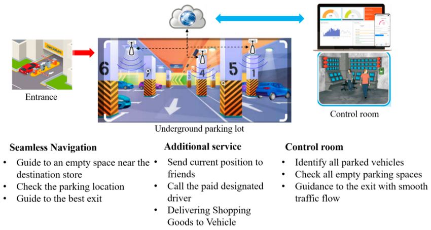
Sensors 2021, 21, 1725                                                                                            3 of 15

                         from a specific area to another area, various candidate groups from the DB are created,
                         and the area with the pattern most similar to the user’s LTE signal pattern is estimated
                         as the current location. Accordingly, in this study, extended subsequence dynamic time
                         warping (ESDTW) is proposed for estimating the position of the vehicle. Within an area, it is
                         possible to estimate the position using subsequence dynamic time warping (SDTW) [26].
                         Further, the rotation of the vehicle is determined through the gyroscope output to establish
                         whether the vehicle is moving to a new area. In the new area, the location is estimated by
                         comparing the new candidate trajectory with the user pattern using SDTW. The candidate
                         generator generates new candidate trajectories using the estimated location and next link
                         information. In addition, it is possible to determine the stopping and moving of a vehicle
                         using the acceleration sensor of a smartphone. To confirm the performance of the proposed
                         system, an experiment is conducted in the underground parking lot of a large shopping
                         mall. The contributions of this study are as follows:
                         •    The accurate position in an underground parking lot is estimated using the accu-
                              mulation pattern of the LTE RSS. In particular, ESDTW is proposed to compare the
                              LTE sequence and DB, and the effectiveness of the proposed technology is verified
                              experimentally.
                         •    The proposed system can estimate the position with sufficient accuracy for providing
                              navigation services in an underground parking lot using only a mobile phone, without
                              requiring additional infrastructure. This technology is easy to use, and it is possible to
                              integrate it with the existing vehicle navigation system based on GNSS.
                              The remainder of this paper is organized as follows: Section 2 describes the configu-
                         ration of the proposed system. Section 3 explains the proposed system and its algorithm.
                         The experimental results and analysis are discussed in Section 4. Finally, the conclusions
                         are presented in Section 5.

                         2. Block Diagram of the Proposed System and Its Applications
                               Figure 1 shows the block diagram of the proposed system. A salient feature of the
                         proposed system is the usage of an accumulated RF signal. Whenever the RF signal
                         strength is received, it is stored in the user’s buffer. Using the acceleration sensor included
                         in the mobile phone, the system checks the movement (stopped/moving) status of the
                         vehicle. If it is determined that the vehicle has stopped, position estimation is not per-
                         formed. The vehicle’s heading and turn motions are estimated using the gyroscope output.
                         The candidate generator generates a candidate trajectory using the estimated position of
                         the vehicle and the turn occurrence information. Finally, the vehicle’s position is estimated
                         employing the proposed method, ESDTW, using the generated candidate trajectories and
                         the user’s RF pattern. Figure 2 depicts the overall configuration of the proposed system and
                         its effectiveness. The ultimate purpose of this research is to provide seamless navigation to
                         users. As depicted in Figure 2, various services are possible using the proposed system,
                         and other services can also be created in combination with the currently implemented
                         service. Hence, a new location-based service (LBS) is offered to users.
Sensors 2021, 21, 1725                                                                                           4 of 15

                         Figure 1. Block diagram of proposed system.

                                      Figure 2. Overall proposed system configuration and its effectiveness.

                         3. Proposed Method
                              The proposed method is similar to the fingerprint, which is extensively used in indoor
                         positioning systems. In the fingerprint method, it is necessary to create a DB by storing the
                         RSS of the surrounding RF signals at each specific position defined in the testbed in advance.
                         During the estimation phase of the actual position, the currently received signal pattern is
                         compared with the DB, and the reference point (RP) with the RSS pattern most similar to
                         the input RSS pattern is estimated as the present position of the user. However, this method
                         significantly decreases the positioning accuracy when the number of RF beacons installed
                         on the test bed is less or when the signal strength is weak. WiFi APs are not installed in an
                         underground parking lot, and only LTE signals are received. In particular, because only
                         one or two base station signals are received, accurate positioning cannot be performed
                         with the existing fingerprint methods. To solve this problem, the accumulated RSS from
                         the LTE was used. This following subsection describes the LTE DB construction, dynamic
                         time warping (DTW), and the proposed method (ESDTW).

                         3.1. LTE DB Construction
                         Testbed
                             In this study, an experiment was conducted in the underground parking lot of a large
                         shopping mall. The parking lot involved a large area in which more than 500 vehicles could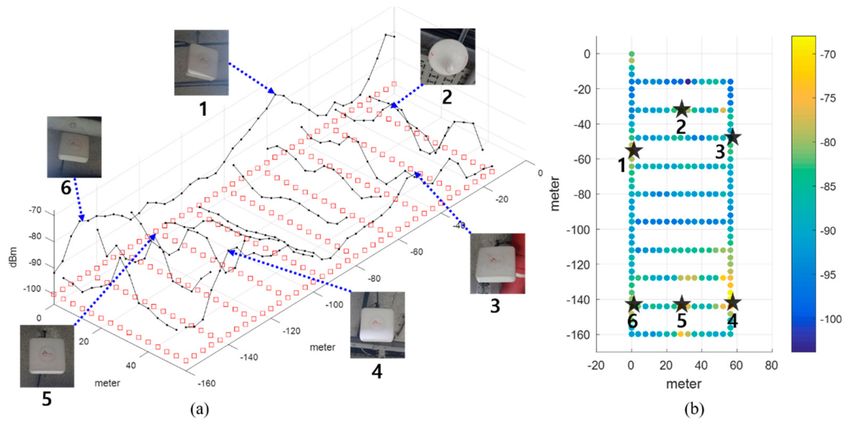
Sensors 2021, 21, 1725 5 of 15
be parked. It was rectangular shaped and contained several corridors. To create the LTE DB,
the RPs were configured at intervals of 4 m, as shown in Figure 3. The LTE DB also stores
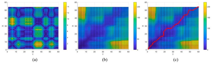
the LTE RSS information received from each RP. Figure 4 depicts the experimental settings.
A smartphone was placed on the dashboard of the vehicle. The sensor data from the
accelerometer and gyroscope and LTE signal were stored in the smartphone. To measure
the distance traveled by the vehicle, velocity data were logged from the onboard diagnostic
2 (OBD2) and used as the reference data in the actual location estimation experiment as
well as for creating the DB. The trajectory of the vehicle can be estimated using the logged
velocity and direction information. Figure 5a displays the vehicle’s movement trajectory
estimated using the OBD2 and gyroscope data. Figure 5b shows the map matching (MM)
results. As the underground parking lot is in the form of a corridor, it can be defined as
nodes and links. The red squares in Figure 6 indicate the nodes. When logging data for
the LTE DB, the vehicle is turned only at a node. Therefore, when the turn of the vehicle
is detected, the position of the vehicle is corrected at the node. As the vehicle moves, the
accumulated error of the trajectory increases because of the velocity and heading errors;
however, this accumulated error is corrected by performing MM at each node. Figure 6
illustrates the definition of the LTE signal strength at each RP. When the vehicle repeatedly
moves along the same path, the LTE RSS sample points continue to increase around the RP.
The value at the final RP is determined by averaging the LTE RSS sample points around
the RP. LTE RSS samples of the same color have the same vehicle trajectory when passing
through the corresponding RP. Figure 7 shows the overall RSS and RPs of the LTE DB in the
underground parking lot. Figure 7a depicts the signal strength of the LTE signal received
in 2D space. It can be observed that at a point where an LTE antenna is installed, the signal
strength is high. It was confirmed that several antennas were installed in the underground
parking lot. However, the physical cell identification (PCI) of the LTE signal received from
each antenna was the same. Figure 7b shows the color map of the LTE DB signal strength.
The closer the RP is to yellow, the stronger is the signal strength.
Figure 3. Reference points definition in underground parking lot.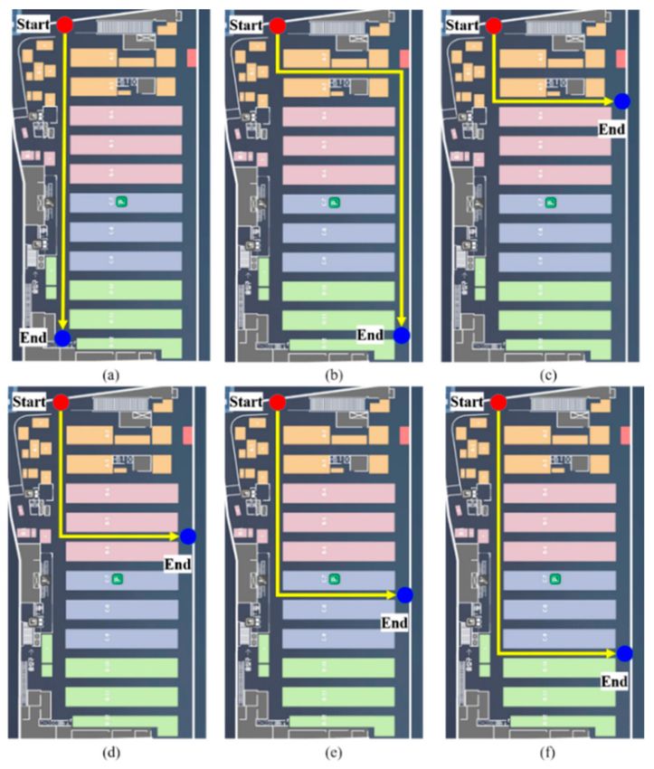
Sensors 2021, 21, 1725                                                                                               6 of 15

                         Figure 4. Experimental setting.

                         Figure 5. Vehicle trajectory by dead reckoning using OBD2 and smartphone. (a) Before map matching;
                         (b) After map matching.

                         Figure 6. Calculation of RP value using LTE RSS collected data.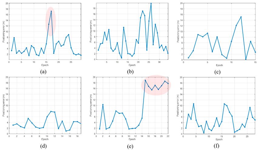
Sensors 2021, 21, 1725                                                                                                7 of 15

                         Figure 7. Overall RSS and RP of the LTE DB in the underground parking lot. (a) LTE RSS distribution
                         of LTE DB; (b) Color map of LTE DB and LTE antenna positions.

                         3.2. DTW
                              As the vehicle moves, the LTE RSS accumulates in the user buffer. The RP sequence
                         that is most similar to the RSS sequence in the user buffer is the current vehicle loca-
                         tion. DTW is an algorithm that determines the optimal alignment of two sequential data.
                         Here, optimal alignment refers to index pairs with the minimum distance between two se-
                         quential data. The DTW finds a pair, even if the speed and length of the two time-sequences
                         are different. We define two sequences X and Y as follows:

                                                            X := ( x1 , x2 , x3 , . . . , x N ),                         (1)

                                                            Y := ( y1 , y2 , y3 , . . . , y M ),                         (2)
                         where N and M are the lengths of sequences X and Y, respectively. The cost matrix C is
                         defined as follows:
                                                C (i, j) = xi − y j 1 ≤ i ≤ N, 1 ≤ j ≤ M                    (3)
                              The accumulated cost matrix UDTW is calculated as:
                                                                                i
                                                           UDTW (i, 1) = ∑ C (k, 1)
                                                                              k =1
                                                                                j                                        (4)
                                                           UDTW (1, j) = ∑ C (1, k )
                                                                              k =1
                             UDTW (i, j) = min{UDTW (i − 1, j − 1), UDTW (i − 1, j), UDTW (i, j − 1)} + C (i, j)

                              Finally, the optimal path P is obtained as

                                            P(i, j) = argmin{U (i − 1, j − 1), U (i − 1, j), U (i, j − 1)}               (5)

                              Figure 8 shows an example of the described DTW. Suppose that the lengths of two
                         sequences X and Y are 54 and 60. The sizes of C and U are 54 × 60, respectively. Figure 8a
                         shows the cost matrix, whereas Figure 8b shows the accumulated cost matrix. Figure 8c
                         displays the final selected optimal path P. Figure 9 depicts the two sequences X and Y. These
                         two sequences are connected by an optimal path that includes the selected pairs. The DTW
                         has the same start and end points as the X and Y sequences. However, there are cases where
                         X is part of Y; i.e., if the physical sequence length of X is smaller than that of Y, the start
                         or end point of X is the middle of the Y sequence. Figure 10 compares examples of DTW
                         and SDTW. In this study, because the LTE RSS is increasingly accumulated, the position is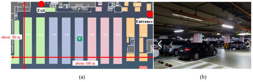
Sensors 2021, 21, 1725                                                                                         8 of 15

                         estimated through SDTW. Algorithmically, DTW and SDTW are identical, except for one
                         part; when calculating USDTW in SDTW, the first row is obtained as follows:

                                                              USDTW (i, 1) = C (i, 1)                             (6)

                         Figure 8. (a) Cost matrix; (b) Accumulated cost matrix; (c) Optimal path.

                         Figure 9. Two sequences connected by optimal path.

                         Figure 10. Comparison between DTW and SDTW. SDTW is applied when the physical length between
                         sequences is different. (a) Aligned sequences using DTW; (b) Aligned sequences using SDTW.

                             This indicates that the first row-element of USDTW is always initialized, and the
                         minimum element of the last row of USDTW is the last pair of optimal paths in SDTW.

                         3.3. Proposed Extended Subsequence DTW
                              In this subsection, the ESDTW proposed in this study is described. An underground
                         parking lot includes several links. As the vehicle moves, it passes through a specific link.
                         As previously mentioned, the LTE RSS accumulates in the user buffer as the vehicle moves
                         and the location of the vehicle in a specific link is estimated through SDTW. When the
                         vehicle enters the next link, the location is estimated using the user buffer and the link
                         combination, in which two links are connected. Here, we call the link combination as the
                         candidate trajectory, which is a combination of links through which the vehicle can move.
                         Moreover, the candidate trajectories are continuously expanded with the addition of new
                         links. The candidate trajectories are generated by the candidate generator using the motion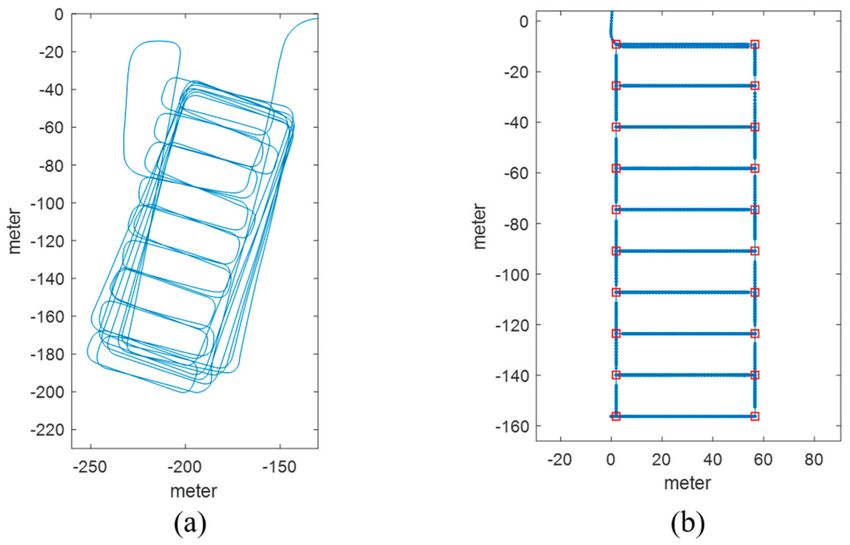
Sensors 2021, 21, 1725                                                                                                     9 of 15

                         information of the vehicle and the previously estimated position. The candidate trajectory
                         containing the links is the candidate for the current location of the vehicle. Figure 11 shows
                         the accumulated cost matrix of the ESDTW according to the vehicle’s movement trajectory.
                         In Figure 11a, there is a total of 12 links, including two vertical and ten horizontal links.
                         The red line denotes the movement trajectory of the vehicle. The blue square denotes the
                         location at which a turn occurs. When a vehicle turns, the candidate trajectory is expanded
                         again through the links that exist after the turn. The black square denotes the vehicle’s final
                         position. In Figure 11b, the red line denotes the final optimal path. As the current vehicle is
                         on link 12, there is a vehicle in the accumulated cost matrix of link 12. If the vehicle enters
                         the green link again, the accumulated cost matrix continues to expand. Figure 12 depicts
                         the situation displayed in Figure 11. The user buffer is divided by the turning motion of
                         the vehicle. The candidate generator generates a possible candidate trajectory containing
                         the accessible links. After the divided buffer subsequence is compared with the link in each
                         candidate DB, the location of the vehicle is determined through the candidate trajectory
                         with the least cost. This method minimizes the candidate trajectory with which the user
                         buffer is compared. This reduces the computational complexity and positional errors.

                         Figure 11. (a) Vehicle trajectory in the links; (b) Vehicle trajectory in the accumulated cost matrix.

                         Figure 12. ESDTW is executed using the user buffer and candidate DB. The user buffer is divided into
                         subsequences based on the vehicle’s turn motion. Each SDTW is performed using the subsequence
                         and selected link.

                         4. Experimental Results
                         4.1. Testbed and Experimental Setup
                             To validate the proposed method, an experiment was conducted in the underground
                         parking lot of a super supermarket (SSM) in Jayang-dong, Seoul. Figure 13 shows the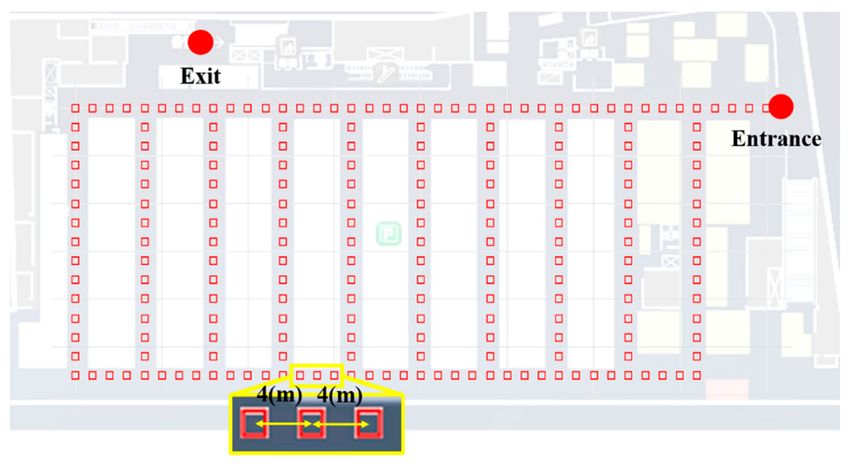
Sensors 2021, 21, 1725                                                                                                     10 of 15

                         corresponding test bed. LTE signals were received in all the areas of the underground
                         parking lot. There were no radio shadow areas, but a very weak signal was received in a
                         particular place, which was far from the LTE antenna.

                         Figure 13. (a) Map of testbed; (b) Front view of underground parking lot.

                               Figure 4 depicts the experimental settings. The experiment was conducted by placing
                         a smartphone on the dashboard. The sensor data, LTE RSS, and OBD2 data were stored
                         in the smartphone. Along with each saved data, the internal clock time was saved, and
                         each data was synchronized using this time. The performance of the proposed method was
                         analyzed by post-processing using the stored data. As mentioned in Chapter 3, velocity
                         data from the vehicle’s OBD2 were used as the reference data to evaluate the performance of
                         the proposed system. The distance moved by the vehicle was estimated using the velocity
                         data of OBD2. The heading was estimated using the gyroscope output, and the reference
                         trajectory was estimated by performing MM. The accumulated error was eliminated by
                         detecting the time at which the vehicle turned and matching the position to a nearby corner
                         point. The mobile phone used in the experiment was the Samsung Galaxy 9+. The OBD2
                         and sensor data were logged at approximately 2 Hz and 50 Hz, respectively. The LTE
                         RSS was updated every 2 s. Figure 14 illustrates the experimental scenarios. A total of six
                         experiments was conducted. Scenarios 1 and 2 evaluated the performance in a straight line;
                         whereas scenarios 3–6 checked the accuracy of position estimation when entering a new
                         link.

                         Figure 14. Test scenarios. (a) scenario 1; (b) scenario 2; (c) scenario 3; (d) scenario 4; (e) scenario 5;
                         (f) scenario 6.
Sensors 2021, 21, 1725 11 of 15
4.2. Result Analysis
Figure 15 displays the positioning results for all the scenarios. Overall, the level of
error is within 20 m, but the positioning results differ for each scenario. In particular, the
red circle indicates the part where the positioning error is large. Due to the nature of the
proposed method, location accuracy tends to be low in regions where RPs with weak signal
strength are uniformly distributed. To accurately estimate the user position with DTW, it is
advantageous to show unique RSS characteristics for each RP. Figure 16 compares the user
buffer and DB candidate when the positioning error is maximum in scenario 1. Both the
DB candidate and the received LTE RSS are weak in the epoch with large positioning error.
If a weak signal is continuously received, there is a possibility that the position error may
increase in an underground parking lot environment where only one LTE PCI is allocated.
Figure 17a shows the 2D position results for scenario 5. The vehicle moves to link C6, but
its position is estimated using link C5. The LTE RSS in the region is also weak, and because
the LTE signal noise is greater than the difference in the signal strength between the two
links, the position is incorrectly estimated. Figure 18 presents the cumulative distribution
function (CDF) of the positioning errors for each scenario. Scenarios 4 and 6 show highly
accurate location-estimation results. Scenarios 2 and 5, which pass through the weak signal
section, show reduced location estimation performance compared to the other scenarios.
Table 1 summarizes the positioning errors for all the test scenarios; the average error is
less than 10 m for all the scenarios. The crucial aspect to consider in this study is the
maximum error. To perform user-oriented and stable navigation, it is necessary to reduce
the maximum error. The maximum error is less than 20 m in all the scenarios.
Figure 15. Positioning error by epoch for each scenario. (a) position error of scenario 1; (b) position
error of scenario 2; (c) position error of scenario 3; (d) position error of scenario 4; (e) position error of
scenario 5; (f) position error of scenario 6.Sensors 2021, 21, 1725 12 of 15
Figure 16. The epoch with the biggest error in scenario 1. Weak RSS is continuously received in
this area.
Figure 17. (a) 2D estimated position in scenario 5; (b) RSS distribution in L5 and L6.
Figure 18. Cumulative distribution function (CDF) for all scenarios.Sensors 2021, 21, 1725 13 of 15
Table 1. Analysis of ESDTW positioning error.
Test Num. Mean (m) RMSE (m) Max (m) CEP (m)
1 4.68 5.87 17.19 4.13
2 6.68 8.32 19.73 5.32
3 5.78 7.35 15.14 6.50
4 3.64 4.15 7.87 3.50
5 9.06 11.26 18.89 7.27
6 4.56 5.47 10.62 4.43
4.3. Discussion
The LTE signal-based underground parking-lot location estimation system has the
advantage of estimating the location using a smartphone alone, without requiring any
additional infrastructure for location estimation. There is currently no alternative for
estimating the location of a vehicle in an underground parking lot, and the proposed
method offers a new navigation system. However, because of the characteristics of the LTE
network, only one LTE PCI is allocated and serviced in an underground parking lot. In
addition, although LTE signals reach all the areas in an underground parking lot, there are
many areas where the signal strength is weak; hence, the location error tends to decrease
in these areas. This problem can be solved by installing a BLE beacon in the area where a
weak signal is received. As BLE signals can also be received by smartphones, it is possible
to compensate for the areas where the LTE RSS is weak. However, the cost of maintenance
and management of the additional infrastructure must be considered. Another method is
to estimate the moving distance of the vehicle using an acceleration sensor. When using
the navigation application, because the smartphone is fixed to the dashboard, it is possible
to obtain relatively stable acceleration sensor output values. If attitude estimation of the
smartphone and calibration can be performed accurately, the use of an acceleration sensor
may be an option.
5. Conclusions
As the services of vehicle navigation applications do not extend to underground
parking lots, a user entering the parking lot must drive the vehicle entirely depending on
his/her own vision. It is not easy for a user to find an appropriate empty parking space in a
spacious and complex underground parking lot. Moreover, it is difficult to find an escalator
or elevator close to the destination, after parking. To solve this problem, an underground
parking lot navigation system using an accumulated LTE signal was presented in this
study. The advantage of the proposed system is that it is possible to navigate using a
smartphone alone, without installing additional infrastructure. The candidate trajectory is
generated by a DB candidate generator, and the vehicle position is estimated by comparing
the user buffer data and candidate trajectory through ESDTW. To evaluate the effectiveness
of the proposed system, a field test was conducted and accurate positioning results were
obtained.
In the future work, we will improve the location estimation performance by combining
the proposed technology and dead reckoning technology and then use this system in multi-
storey underground parking lots. As the proposed technology is combined with the existing
navigation system, users do not need to install a separate application. When a vehicle
enters the underground parking lot, the navigation screen automatically changes to the
underground parking lot map, allowing a driver to experience a new seamless navigation.
Author Contributions: This research was carried out in collaborations with all authors. B.S., J.H.L.,
C.Y., C.K. and T.L. designed the proposed method. B.S., and J.H.L. performed the experiment and
analyzed the experimental results. B.S. drafted the manuscript. C.K. and T.L. corrected the whole
manuscript. All authors contributed and improved the manuscript. All authors have read and agreed
to the published version of the manuscript.Sensors 2021, 21, 1725 14 of 15
Funding: This work was supported by the National Research Council of Science & Technology
(NST) grant by the Korea government (MSIT) [CRC-20-02-KIST] and also supported in part by the
Institute for Information and Communications Technology Program (IITP) Grant funded by the
Korea Government (Ministry of Science and ICT, MSIT) under Grant 2019-0-01401, in part by the
Multi-source based 3D Emergency LOCalization using machine learning techniques (MELOC).
Institutional Review Board Statement: Not applicable.
Informed Consent Statement: Informed consent was obtained from all subjects involved in the
study.
Data Availability Statement: Not applicable.
Conflicts of Interest: The authors declare no conflict of interest.
References
1. Ye, H.; Jing, X.; Liu, L.; Hao, S.; Yu, B. Analysis of the Multiplexing Method of New System Navigation Signals of GPS III First
Star L1 Frequency in China’s Regional. Sensors 2019, 19, 5360. [CrossRef] [PubMed]
2. Kim, C.; So, H.; Lee, T.; Kee, C. A Pseudolite-Based Positioning System for Legacy GNSS Receivers. Sensors 2014, 14, 6104–6123.
[CrossRef] [PubMed]
3. Xu, R.; Chen, W.; Xu, Y.; Ji, S. A new indoor positioning system architecture using gps signals. Sensors 2015, 15, 10074–10087.
[CrossRef] [PubMed]
4. Liu, F.; Wang, J.; Zhang, J.; Han, H. An indoor localization method for pedestrians base on combined UWB/PDR/floor map.
Sensors 2019, 19, 2578. [CrossRef] [PubMed]
5. Alletto, S.; Cucchiara, R.; Del Fiore, G.; Mainetti, L.; Mighali, V.; Patrono, L.; Serra, G. An Indoor Location-Aware System for.
IEEEE Internet Things 2016, 3, 244–253. [CrossRef]
6. Spachos, P.; Plataniotis, K.N. BLE beacons for indoor positioning at an interactive IoT-based smart museum. IEEE Syst. J. 2020, 14,
3483–3493. [CrossRef]
7. Yadav, R.K.; Bhattarai, B.; Gang, H.S.; Pyun, J.Y. Trusted K nearest Bayesian estimation for indoor positioning system. IEEE Access
2019, 7, 51484–51498. [CrossRef]
8. Giuliano, R.; Cardarilli, G.C.; Cesarini, C.; Di Nunzio, L.; Fallucchi, F.; Fazzolari, R.; Mazzenga, F.; Re, M.; Vizzarri, A. Indoor
localization system based on bluetooth low energy for museum applications. Electronics 2020, 9, 1055. [CrossRef]
9. Qiu, X.; Wang, B.; Wang, J.; Shen, Y. AOA-based BLE localization with carrier frequency offset mitigation. In Proceedings of the
2020 IEEE International Conference on Communications Workshops (ICC Workshops), Dublin, Ireland, 7–11 June 2020; pp. 2–6.
10. Monfared, S.; Nguyen, T.H.; Petrillo, L.; De Doncker, P.; Horlin, F. Experimental Demonstration of BLE Transmitter Positioning
Based on AOA Estimation. In Proceedings of the 2018 IEEE 29th Annual International Symposium on Personal, Indoor and
Mobile Radio Communications (PIMRC), Bologna, Italy, 9–12 September 2018; pp. 856–859.
11. Wu, T.; Liu, J.; Li, Z.; Liu, K.; Xu, B. Accurate smartphone indoor visual positioning based on a high-precision 3D photorealistic
map. Sensors 2018, 18, 1974. [CrossRef] [PubMed]
12. Hassan, N.U.; Naeem, A.; Pasha, M.A.; Jadoon, T.; Yuen, C. Indoor positioning using visible LED lights: A survey. ACM Comput.
Surv. 2015, 48, 1–32. [CrossRef]
13. Shin, B.; Kim, C.; Kim, J.; Lee, S.; Kee, C.; Kim, H.S.; Lee, T. Motion Recognition-Based 3D Pedestrian Navigation System Using
Smartphone. IEEE Sens. J. 2016, 16, 6977–6989. [CrossRef]
14. Kang, W.; Han, Y. SmartPDR: Smartphone-based pedestrian dead reckoning for indoor localization. IEEE Sens. J. 2015, 15,
2906–2916. [CrossRef]
15. Shin, S.H.; Lee, M.S.; Park, C.G.; Hong, H.S. Pedestrian dead reckoning system with phone location awareness algorithm. In
Proceedings of the IEEE/ION Position, Location and Navigation Symposium, Indian Wells, CA, USA, 4–6 May 2010; pp. 97–101.
16. Shin, B.; Lee, J.H.; Lee, H.; Kim, E.; Kim, J.; Lee, S.; Cho, Y.S.; Park, S.; Lee, T. Indoor 3D pedestrian tracking algorithm based on
PDR using smarthphone. Int. Conf. Control. Autom. Syst. 2012, 1442–1445.
17. Molina, B.; Olivares, E.; Palau, C.E.; Esteve, M. A multimodal fingerprint-based indoor positioning system for airports. IEEE
Access 2018, 6, 10092–10106. [CrossRef]
18. Shin, B.; Lee, J.H.; Lee, T.; Kim, H.S. Enhanced weighted K-nearest neighbor algorithm for indoor Wi-Fi positioning systems.
In Proceedings of the 2012 8th International Conference on Computing Technology and Information Management (NCM and
ICNIT), Seoul, Korea, 24–26 April 2012; pp. 574–577.
19. Ma, R.; Guo, Q.; Hu, C.; Xue, J. An improved WiFi indoor positioning algorithm by weighted fusion. Sensors 2015, 15, 21824–21843.
[CrossRef] [PubMed]
20. Li, N.; Gao, Y.; Wang, Y.; Liu, Z.; Guan, L.; Liu, X. A low-cost underground garage navigation switching algorithm based on
kalman filtering. Sensors 2019, 19, 1861. [CrossRef] [PubMed]
21. Zhao, Z.; Wang, J.; Zhao, X.; Peng, C.; Guo, Q.; Wu, B. NaviLight: Indoor localization and navigation under arbitrary lights. In
Proceedings of the IEEE INFOCOM 2017—IEEE Conference on Computer Communications, Atlanta, GA, USA, 1–4 May 2017;
pp. 1–9.Sensors 2021, 21, 1725 15 of 15
22. Jia, Y.; Jin, Z.; Zhang, H.; Li, Y.; Wang, X.; Shen, L. Indoor navigation for a complex parking building based on computer vision. In
Proceedings of the 2019 5th International Conference on Transportation Information and Safety (ICTIS), Liverpool, UK, 14–17
July 2019; pp. 183–190.
23. Hirakata, Y.; Nakamura, A.; Ohno, K.; Itami, M. Navigation system using ZigBee wireless sensor network for parking. In
Proceedings of the 2012 12th International Conference on ITS Telecommunications, Taipei, Taiwan, 5–8 November 2012; pp.
605–609.
24. Lee, J.H.; Shin, B.; Shin, D.; Park, J.; Ryu, Y.S.; Woo, D.H. Surface Correlation-Based Fingerprinting Method Using LTE Signal for
Localization in Urban Canyon. Sensors 2019, 19, 3325. [CrossRef]
25. Zhang, P.; Zhao, Q.; Li, Y.; Niu, X.; Zhuang, Y.; Liu, J. Collaborative WiFi fingerprinting using sensor-based navigation on
smartphones. Sensors 2015, 15, 17534–17557. [CrossRef] [PubMed]
26. Anguera, X.; Ferrarons, M. Memory efficient subsequence DTW for Query-by-Example Spoken Term Detection. In Proceedings of
the 2013 IEEE International Conference on Multimedia and Expo (ICME), San Jose, CA, USA, 15–19 July 2013; pp. 2–7.You can also read