INSTALLATION & USER MANUAL - for Undercounter WOW RO Systems Place Data Label Here
←
→
Page content transcription
If your browser does not render page correctly, please read the page content below
INSTALLATION & USER MANUAL
                    for
       Undercounter WOW RO Systems

                                Place Data Label Here

                               Scan with QR Reader App
                       Visit our website: www.wowwater.com

                   Powered by

23880 Madison Street, Torrance, CA 90505 - (310) 375-5000 - www.wowwater.com
                                  V12-1.23.18
Introduction to The WOW RO System
The WOW RO System operates by removing contaminants from water at the molecular level. By
using your household water pressure to squeeze your water against a special membrane, water
molecules are separated from impurities. Rejected dissolved solids are automatically rinsed down
the drain leaving only high-quality, delicious water for you to use.

 General Information
1. The WOW RO System will replenish approximately 1.5 gallons (5.7 L) in 35–90 minutes, de-
   pending on your incoming water pressure, quality and temperature. This appliance is designed
   with a self-regulating flush feature that limits the reject water to approximately 2 gallons (7.6 L)
   for every gallon (liter) of treated water. Your appliance will perform better and last longer with
   heavy use. We encourage you to water house plants, provide water for pets, cook, mix drinks,
   fill batteries, etc., with treated water. Caution: The working capacity of this appliance depends
   on the pressure and temperature of the water supply. This appliance is not guaranteed to
   work properly with water pressure less than 20 psi (1.4 bar) and water temperature less than
   40°F (4°C).

                                   Figure 1: Installation Diagram

2. The storage tank will store 1.5 gallons (5.7 L) of water.
3. The WOW RO System can be connected to a variety of appliances, including your automatic ice
   maker, cold water dispenser in the refrigerator door, coffee maker, water cooler and other
   commercial applications.
4. The WOW RO System is designed to be connected to cold water only.
                        Caution: Never run hot water through your appliance.
5. The flow of water through your treated water faucet will not be as strong as your sink faucet.
6. The WOW RO System is made of safe, non-toxic, health and environment-friendly materials.
   BPA Free.
                      Warning: Do not allow your appliance to freeze.

                                                    2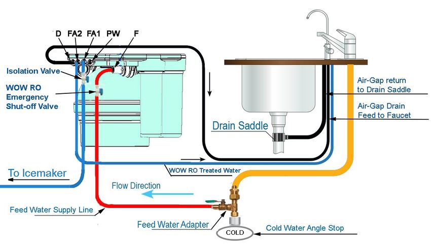
Contents
Introduction to The WOW RO System ....................................................................................... 2
General Information ................................................................................................................... 2
Section 1-Installation & Start-up Procedures ........................................................................... 5
Avoid Common Mistakes............................................................................................................ 6
Pre-installation Checklist ............................................................................................................ 7
Installation Tool List ................................................................................................................... 7
Installation Kit Contents ............................................................................................................. 8,9
Part Inspection ........................................................................................................................... 10
Proper Placement of Filters ........................................................................................................ 10
Installing Filter Cartridges .......................................................................................................... 11
Connecting the System ............................................................................................................... 12
Start-up Procedure ..................................................................................................................... 13
Section 2-Connecting Additional Appliances to WOW RO System ......................................... 14
Connecting to Multiple Appliances ............................................................................................ 15
Refrigerator/Ice-maker/Coffee-maker/Cooler setup ................................................................ 16-21
Section 3– When More Water is Needed ................................................................................. 22
Adding Extra Storage Tanks ........................................................................................................ 23
Modular Expandability ............................................................................................................... 24
Section 4-Plumbing the Sink ...................................................................................................... 25
Install Drain Saddle Assembly .................................................................................................... 26
Prepare Sink for RO Faucet Installation ..................................................................................... 27
Install Incoming Water Supply Valve.......................................................................................... 28
Section 5-Maintenance .............................................................................................................. 29
Changing Filters .......................................................................................................................... 30
Recommended Filter Replacement ............................................................................................ 31
WOW RO System Appliance ....................................................................................................... 32
Sanitizing Water-on-Water ........................................................................................................ 33
Notes .......................................................................................................................................... 34
Section 6-Troubleshooting ........................................................................................................ 35
Troubleshooting Tables .............................................................................................................. 36,37
Owner Information .................................................................................................................... 38
2 Year Limited Warranty ........................................................................................................... 39

                                                                             3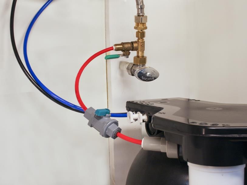
Figure 1: Installation Diagram

4
Section 1

Installation & Start-up Procedures

                5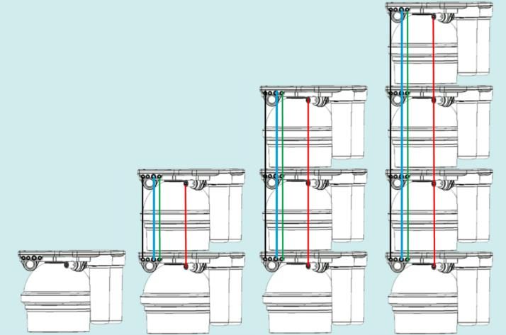
Installation Steps and Start-Up Procedures

                               AVOID COMMON MISTAKES !

Review the most common missed steps made BEFORE starting. This will ensure an easy and
successful installation.
1.     Prepare and install all service components such as RO faucet, drain, and valve before
       installing WOW RO System (Pages 26-28).
2.     Fully pre-load filter cartridges according to Step 3 (Page 11) to remove all air before
       attaching to system.
3.     When installing pre-loaded filters to system, you MUST make sure they are properly
       attached and engaged to the stop tabs per Step 3 (Figure 3, Page 11) instructions.
       Filters are labeled PRE, POST and RO. Ensure each filter matches position on RO unit
       manifold.
4.     If replacing an existing RO unit under the sink, you MUST ensure an independent iso-
       lation valve is used between the WOW RO System and any added outlets. Without an
       isolation valve, the WOW RO System will not start. Refer to Section 2 for connecting
       additional appliances.
5.     Before beginning Start-up Procedures (Step 5, Page 13) make sure all tube connections
       match the Figure 1 diagram on Page 4.
6.     Make sure unit is ONLY connected to a cold water supply (Page 7).
7.     If your connections to and from WOW RO System have a leak (even one drop), the sys-
       tem will not work. Repair leak (see Troubleshooting if necessary) and repeat Start-up
       Procedures (Step 5, Page 13).
8.     To avoid air-gap overflowing onto counter, air-gap return line must never have loops or
       sags in tubing.
9.     If you are not using WOW’s RO installation kit, it is critical that installers use correct
       color coded tubing (See installation kit contents, Page 8) to ensure easy trouble
       shooting or add-on appliance follow-up.
10..   If replacing an existing RO unit, make sure you replace all old tubing with new color
       coded tubing.

                                                 6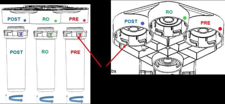
Installation Steps and Start-Up Procedures
Warning: Installation of this appliance must conform with state and local plumbing codes,
laws, regulations, and the instructions provided with this appliance. Failure to install as in-
structed will void the product warranty.
    Step 1   Pre-Installation Checklist
• Look under sink to identify where the unit will rest.
• To identify hot from cold, turn on hot water at the sink until hot water is flowing. Touch
  pipes below and mark cold from hot.
• Identify desired location for new faucet and mark sink for drilled hole, unless hole is pre-
  existing.
• Review tool kit supplies needed (Table 1).
• Open box and confirm 3 filter cartridges (PRE, POST & RO), 1 RO unit (tank & manifold)
  and installation kit (if purchased *).
* If installation kit is not purchased, you will need:
    3— 4’ x 1/4” tubing
    1— 3/8” drain saddle (sized for air-gap or non air-gap)
    1— 3/8” tubing if air-gap is desired
    1— Feed water adapter
    1— 1/4” WOW RO emergency shut-off valve
    1— Faucet with appropriate connector to 1/4” tubing

                      Recommended Tool List                  Professional Installers “Must Have” Tool List
         Relton drill 1-1/4” assembly (HST-20)           2 pressure gauges adapted to 1/4” tube
         (porcelain sinks)

         Greenlee 1/2” to 1-1/4” punch                   Conductivity or TDS meter
         (stainless steel sinks)

         1” to 1-1/4” Carbide drill bit or hole saw      Tubing cutter or sharp knife
         7/16” open-end wrench
         1/2” open-end wrench
         9/16” open-end wrench
         5/8” open-end wrench
         Medium-sized (#2) Phillips screwdriver

                                                    Table 1:
                                              Recommended Tool List
                                                         7
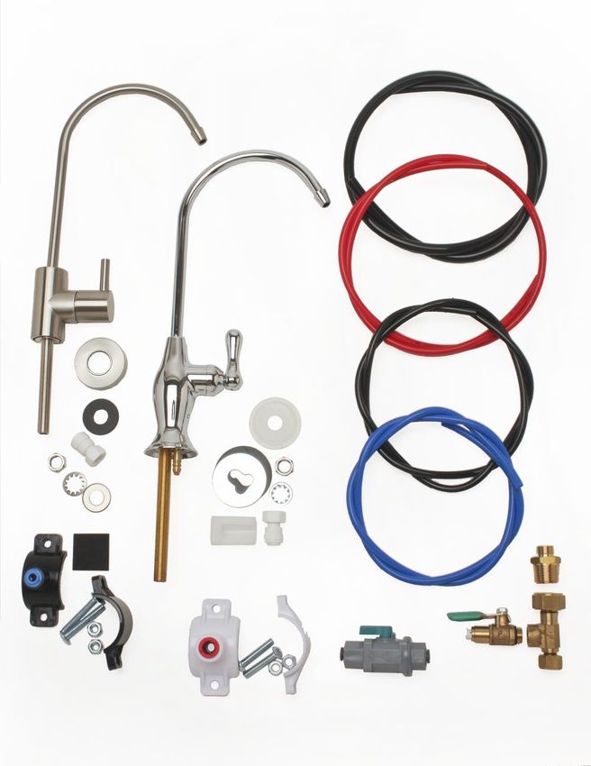
Installation Kit Contents

          A

                       B

                                            I

     C             D

          G

    E

                                    G   H
                            F

                                8
Installation Kit Legend

A. Non air-gap faucet
B. Air-gap faucet
C. Non air-gap faucet hardware
D. Air-gap faucet hardware
E. Drain saddle—(1/4”)
F. Drain saddle—(3/8”)
G. 1/4” WOW RO emergency shut-off valve
H. Feed water adapter
I. Tubing for install connections:
  •   Black 3/8” - Air-gap return line to 3/8”drain saddle
  •   Black 1/4” - Air-gap drain feed to faucet/D port to non air-gap
      drain saddle
  •   Red 1/4”
  •   Blue 1/4”

                                     9
Installation Steps and Start-Up Procedures
 Step 2 Inspect Unit Parts from Box

Cartridge Inspection:
 • Remove red cap on pre-filter and post-filter.
    • Confirm that external large O-Ring is in place.
    • Confirm that 2 smaller O-Rings are in place (located in center).
 • Remove red cap on RO-filter.
    • Confirm that large external O-Ring is in place.
    • Confirm that medium O-Ring is in place.
    • Confirm that 2 small O-Rings are in place (located in center).
• If any O-Rings are missing, please call our service center: (866) 790-8911 ext: 4

 Proper Placement of Filters

                                    Caution:
                         Cartridges must line up with tank
                              cutouts when present
                       Newer systems may not have cutouts

                                        Figure 2:
                                          10
Installation Steps and Start-Up Procedures
Step 3 Install Filtration Cartridges
1. Remove red cap from top of filter cartridge.
2. With a black permanent marker, write the date on each filter to track replacement time. Filters
last up to a year.
3. Pre-fill filter cartridges with bottled water or tap water until it overflows from the top. Wait
3 minutes and top off as cartridges soak up water. Repeat until cartridges are completely
saturated and no air is present at the top.
Figure 3a:
4. Attach post-filter in the labeled POST position, RO-Filter in the labeled RO position and the pre
-filter in the labeled PRE position, with a twisting counter clockwise upward motion until
you feel and hear stop tabs touch and colored dots are aligned (see Figure 3), .
Figure 3b: POST RO PRE POST RO PRE
Figure 3c:
Warning: Check to see if the cartridges are fully engaged. Visually confirm colored dots are lined up and
white cartridge stop tabs are flush with black manifold stop tabs prior and after pressurization of system.
11Installation Steps and Start-Up Procedures
Step 4 Connect the System
WOW RO System port identification markings molded into top of
manifold: (See Figure 4).
• F: Feed (¼” red)
• D: Drain (¼” black)
• FA1: Faucet/Accessory 1 (⅜” blue)
• FA2: Faucet/Accessory 2 (¼” blue)
• PW: Used for testing or additional storage.
• SQ: Used for testing or additional storage.
• RF: Do not touch (pre-connected). Figure 4:
System Connections
NOTE: Ports that are not used require the appropriate sized plug.
(Included).
A. With the WOW RO System in place, remove any port plugs as necessary (push in white collet to
release) and make the following connections:
B. Feed F connection: Take the 1/4” red tubing and snip off a 6” length. Take long end of remain-
ing tubing and attach to feed water adapter (cold water supply). Attach other end to WOW RO
System emergency shut-off valve (in installation kit). With 6” tubing, attach one end to WOW
RO System emergency shut-off valve and the other end to gray “F” port (See Figure 1, Page 4:
Installation Diagram).
C. Drain D connection:
i. Air-Gap Faucet
Route the free end of the 1/4” black tubing attached to the RO faucet air-gap to the connec-
tion marked “D”.
ii. Non Air-Gap Faucet *
Route drain line connection (saddle clamp or other) to the connection marked “D”, using
the 1/4” black tubing.
* Check local plumbing codes for compliance when using non air-gap faucets.
D. RO Faucet connection:
FA1 (3/8”) or FA2 (1/4”) If there are no additional appliances (i.e. icemaker, coffee maker,
cooler, etc.) to hook up then you have the choice of using either port for the RO faucet.
i. If the RO faucet is more than ten feet in distance from the WOW RO System, then the 3/8”
FA1 port is preferred.
ii. Use the 1/4” FA2 port for the RO faucet and the 3/8” FA1 port for the added appliances.
Note: If your installation needs to connect to multiple appliances, such as an icemaker or coffee
maker, go to Section 2, Pages 15-21
12Installation Steps and Start-Up Procedures
Step 5 Start-up Procedure
Before the WOW RO System is operational, it must be properly primed by removing all air from
the unit.
Purging the system:
A. Make sure the RO faucet and all other outlets using an isolation valve are CLOSED.
B. Turn feed valves (a.k.a. supply valves) on. Notice the sound of water filling the system.
C. Within 3-4 minutes, the waste line from the system will open with a noticeable exhaust of
air and water.
D. After waiting another minute, open RO faucet. Notice air/water exhausting from faucet
port. Wait for a steady stream of water and then CLOSE the faucet.
E. Within 2 minutes, the waste port will open again with a shot of air/water exhausting. At
this point, let the tank fill for approximately 45 minutes.
F. After system shuts down (indicated by no audible or visible drain flow), open RO faucet and
empty system to a trickle. At this point, the system should have generated a full gallon and
a half of water. If not, see Note 1 below or refer to Troubleshooting Guide (Page 35).
G. Turn off RO faucet and let water make-up process refill tank (approximately 45 minutes).
H. The unit is operational, but it is recommended to repeat this process (Steps F & G) up to five
times to completely prep and flush filter cartridges and ensure TDS levels are at their mini-
mums. This will guarantee the best tasting water immediately.
I. System is now fully operational! If system does not work, refer to Troubleshooting Guide.
Note 1: If your connections along any FA lines have a leak (even one drop), the system
will not work. Repair leak and repeat Start-up Procedure.
Note 2: See Pages 15-21 if adding any appliances.
Note 3: Unlike traditional air caprive RO systems, the WOW RO System will always have
water in the tank. This fact does not change the need to follow Steps A-F for start-up.
13Section 2
Connecting Additional Appliances to
WOW RO System
There are many reasons why additional storage is required. If the unit is installed in houses with
larger families, cooking needs alone may warrant more storage. If family fills water bottles ex-
ceeding 1½ gallons at same time, additional storage will be required. In addition, devices with
larger storage capacities like coolers will require greater draw down needs. Draw down refers to
amount of water that is released when opening up faucet and emptying tank from start to finish
(single pull). A standard WOW RO System holds 1½ gallons. The WOW RO System has been de-
signed in a modular format to add additional storage tanks as needed.
14Connecting to Multiple Appliances
The WOW RO System is uniquely designed to connect to one or more appliances (Figure 5), includ-
ing refrigerator icemakers/door dispensers, coolers (both gravity fed and pressurized), under-the-
counter hot & cold vented systems, commercial steamers (restaurants), commercial coffee makers
and other appliances that benefit from RO water. This section addresses “Do’s and Don’ts” of con-
necting to one or more appliances. It also addresses how to determine storage and expansion
needs depending on how many appliances are hooked up.
General MUST Do’s for connecting ANY additional appliances:
A. It’s a must that the filter and water lines to any and all added
outlets be clear of air. Note: System will not work with air in
the lines.
B. Close isolation lines to all additional outlets.
C. Charge system to its full status (refer to Start-up, Page 13).
D. Follow the instructions provided from Pages 16-22.
Determining Your Expansion and Storage Needs:
A standard WOW RO System holds 1½ gallons. The WOW RO System has been designed in a mod-
ular format to add additional storage tanks as needed.
Review chart below for each device connected. Add all additional tanks needed from right hand
column to determine complete storage needs.
Device Average Reservoir in Estimated Additional Tanks
Gallons * Needed
Refrigerator / Icemaker 0 gallons None
Commercial Coffee Maker 1 gallon 0-1
Depending on draw down
needs at peak periods (See
Page 14 for draw down defini-
tion). Count glass/cups per
hour to determine if greater
than 1 gallon.
Gravity Cooler Up to 3 gallons 1
Pressurized Cooler Up to 3 gallons 1
Vented Hot Box 2/3 of a gallon or 84 oz. 0
* Check device manual for actual reservoir capacity.
15Adding a Refrigerator/Icemaker
Refrigerator Hook-ups: (Figure 7, Page 17)
Adding a line from the WOW RO System to your refrigerator will provide
you with clean tasting water and clearer, harder ice cubes.
Isolation (shut-off) Valve
Adding a refrigerator hook-up from a new WOW (dry) installation:
a. Remove the 3/8” plug from the FA1 port by pushing on the white
collet, releasing the plug.
b. Connect the 3/8” plastic tubing to the FA1 port that goes to the ice-
maker.
c. Make sure that a 3/8” isolation/shut-off valve is installed at the sys-
tem in the icemaker line and easily accessible under the sink cabinet
(Figure 6).
d. Close isolation valve. Figure 6
e. Go to Start-up Procedures (Page 13) and proceed until fully operational.
f. After start-up, open isolation valve and bleed line to icemaker as described below (Bleeding
Lines).
Adding a refrigerator hook-up from a pre-installed WOW (wet) installation:
a. Close feed water valve.
b. Open faucet to relieve pressure on the FA ports.
c. Remove the 3/8” plug from the FA1 port by pushing on the white collet, releasing the plug.
d. Connect the 3/8” plastic tubing to the FA1 port that goes to the icemaker.
e. Make sure that a 3/8” isolation/shut-off valve is installed at the system in the icemaker line
and easily accessible under the sink cabinet (Figure 6).
f. Close isolation valve.
g. Turn on feed water.
h. Open isolation valve.
i. Bleed line to icemaker as described below (Bleeding Lines).
Bleeding Lines:
• Refrigerator with no door dispenser:
• Open up freezer and clear ice cube tray.
• Push lever down to engage ice-making. This will begin clearing air out of line.
• Refrigerator with door dispenser:
• Use glass to engage water dispensing and wait for a solid stream of water.
16Figure 7
Refrigerator Icemaker
17Adding a Coffee Maker
Commercial Coffee Maker Hook-ups: (Figure 8A, Page 21)
Adding a line from the WOW RO System to a commercial coffee maker
will ensure RO water is always being used to create great tasting coffee
Isolation (shut-off) Valve
and reducing or eliminating scaling.
Adding a coffee maker hook-up from a new WOW (dry) installation:
a. Remove the 3/8” plug from the FA1 port by pushing on the white
collet, releasing the plug.
b. Connect the 3/8” plastic tubing to the FA1 port that goes to the coffee
maker.
c. Make sure that a 3/8” isolation/shut-off valve is installed at the system
in the coffee maker line and easily accessible under the sink cabinet
(Figure 6). Figure 6
d. Close isolation valve.
e. Go to Start-up Procedures (Page 13) and proceed until fully operational.
f. After start-up, open isolation valve and bleed line to coffee maker as described below
(Bleeding Lines).
Adding a coffee maker hook-up from a pre-installed WOW (wet) installation:
a. Close feed water valve.
b. Open faucet to relieve pressure on the FA ports.
c. Remove the 3/8” plug from the FA1 port by pushing on the white collet, releasing the plug.
d. Connect the 3/8” plastic tubing to the FA1 port that goes to the coffee.
e. Make sure that a 3/8” isolation/shut-off valve is
installed at the system in the coffee maker line
and easily accessible under the sink cabinet
(Figure 6).
f. Close isolation valve.
g. Turn on feed water.
h. Open isolation valve.
i. Bleed line to coffee maker as described below
(Bleeding Lines).
Bleeding Lines:
Brew a pot of coffee.
18Adding a Cooler
Water Cooler Hook-ups: (Figure 8A, Page 21)
Adding a line from the WOW RO System to a cooler will ensure RO water is always being used to
create great tasting water. When adding devices with larger storage capacities, like coolers, you
must first determine draw down needs.
Refer to Section 2, Page 14-15, “Determining your Expansion Needs”. Isolation (shut-off) Valve
Adding a cooler hook-up from a new WOW (dry) installation:
a. Remove the 3/8” plug from the FA1 port by pushing on the white
collet, releasing the plug.
b. Connect the 3/8” plastic tubing to the FA1 port that goes to the cooler.
c. Make sure that a 3/8” isolation/shut-off valve is installed at the system
in the cooler line and easily accessible under the sink cabinet (Figure
6).
d. Close isolation valve. Figure 6
e. Go to Start-up Procedures (Page 13) and proceed until fully operational.
f. After start-up, open isolation valve and bleed line to cooler as described below (Bleeding
Lines).
Adding a cooler hook-up from a pre-installed WOW (wet) installation:
a. Close feed water valve.
b. Open faucet to relieve pressure on the FA ports.
c. Remove the 3/8” plug from the FA1 port by pushing on the white collet, releasing the plug.
d. Connect the 3/8” plastic tubing to the FA1 port that goes to the cooler.
e. Make sure that a 3/8” isolation/shut-off valve is installed at the system in the cooler line and
easily accessible under the sink cabinet (Figure 6).
f. Close isolation valve.
g. Turn on feed water.
h. Open isolation valve.
i. Bleed line to cooler as described below (Bleeding Lines).
Bleeding Lines:
Open spigot to dispense water and
wait for a solid stream of water.
Pressurized Cooler Gravity Cooler
19Adding a Hot Tank w/ Vented Faucet
Hot Tank Hook-ups: (Figure 8-B)
Adding a line from the WOW RO System to a hot tank will ensure RO water is always being used to
create great tasting hot water. When adding devices with larger storage capacities, like hot
tanks, you must first determine draw down needs.
Refer to Section 2, Page 14-15, “Determining your Expansion Needs”. Isolation (shut-off) Valve
Adding a hot tank hook-up from a new WOW (dry) installation:
a. Remove the 3/8” plug from the FA1 port by pushing on the white
collet, releasing the plug.
b. Connect the 3/8” plastic tubing to the FA1 port that goes to the hot
tank.
c. Make sure that a 3/8” isolation/shut-off valve is installed at the sys-
tem in the hot tank line and easily accessible under the sink cabinet
(Figure 6).
d. Close isolation valve. Figure 6
e. Go to Start-up Procedures (Page 13) and proceed until fully operational.
f. After start-up, open isolation valve and bleed line to hot tank as described below (Bleeding
Lines).
Adding a hot tank hook-up from a pre-installed WOW (wet) installation:
a. Close feed water valve.
b. Open faucet to relieve pressure on the FA ports.
c. Remove the 3/8” plug from the FA1 port by pushing on the white collet, releasing the plug.
d. Connect the 3/8” plastic tubing to the FA1 port that goes to the hot tank.
e. Make sure that a 3/8” isolation/shut-off valve is installed at the system in the hot tank line
and easily accessible under the sink cabinet (Figure 6).
f. Close isolation valve.
g. Turn on feed water.
h. Open isolation valve.
i. Bleed line to hot tank as described below (Bleeding Lines).
Bleeding Lines:
20Figure 8-A
Ice-maker, Coffee-maker, Water Cooler
Isolation Valve
To Faucet
To Coffee Maker
To Water Cooler
To Icemaker
Figure 8-B
Hot Tank, Vented Faucet Installation
21Section 3
When More Water is Needed
There are many reasons why additional storage is required. If the unit is installed in houses with
larger families, cooking needs alone may warrant more storage. If family fills water bottles ex-
ceeding 1½ gallons at same time, additional storage will be required. In addition, devices with
larger storage capacities like coolers will require greater draw down needs. Draw down refers to
amount of water that is released when opening up faucet and emptying tank from start to finish
(single pull). A standard WOW RO System holds 1½ gallons. The WOW RO System has been de-
signed in a modular format to add additional storage tanks as needed. Review chart below for
each device connected. Add all additional tanks needed from right hand column to determine
complete storage needs.
Device Average Reservoir in Estimated Additional Tanks
Gallons * Needed
Refrigerator / Icemaker 0 gallons None
Commercial Coffee Maker 1 gallon 0-1
Depending on draw down
needs at peak periods (See
Section 3, Page 22 for draw
down definition). Count glass/
cups per hour to determine if
greater than 1 gallon.
Gravity Cooler Up to 3 gallons 1
Pressurized Cooler Up to 3 gallons 1
Vented Hot Box 2/3 of a gallon or 84 oz. 0
* Check device manual for actual reservoir capacity.
22When More Water is Needed / Desired
Steps to determine storage needs: See Section 2, Page 15
Adding extra storage tanks:
a. Open RO faucet and drain off at least a couple cups of water to release pressure on the inter-
nal bladder.
b. Wait until you hear the pressure release from the drain line.
c. Turn the feed valve off.
d. Remove the ¼” plugs from the SQ (Squeeze) and PW (Tank, Product Water) ports by pushing in
white collet to release.
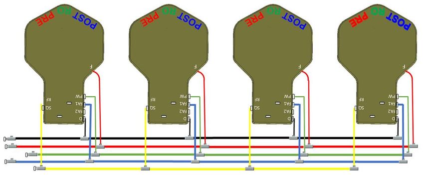
e. Connect ¼” yellow tubing between the matching SQ ports on the WOW RO System manifold
and the spare tank adapter connected to the spare tank (See Figure 9 below for one or multi-
ple tank set-ups).
f. Connect ¼” green tubing between the matching PW ports on the manifold and the adapter
(See Figure 9 below for one or multiple tank set-ups).
g. After connections are completed, slowly turn on feed water and open faucet. You will hear a
combination of air and water eliminated from system. Leave open until a solid stream of water
dispenses.
h. Close the faucet.
i. In less than a minute, control module will activate and system will resume making water with a
noticeable exhaust of air and water down the drain.
j. To expel all air from the newly added tank, it may be necessary to drain water from faucet
several times.
MANIFOLD MANIFOLD
Figure 9: Multiple Tanks
SPARE TANKS
SPARE TANK
23Modular Expandability
Parallel Processing:
24Section 4
Plumbing the Sink
25Install the Drain Saddle Assembly
The drain saddle assembly should be installed above the P-trap on the vertical or horizontal tail-
piece (See Figure 10 below). Use the black 1/4” saddle for the non air-gap RO faucet, or the white
3/8” saddle for the air-gap RO faucet.
A. Position the drain saddle in the desired location, mark the spot to be drilled, and remove the
saddle. (See Figure 10).
B. Drill a 7/16” hole through one side of the drain pipe only.
Figure 10:
Drain Saddle Assembly Mounting
Locations
C. Peel off the paper backing from the drain gasket and apply the gasket to the “port” connection
of the drain saddle (See Figure 11).
D. Make sure to align the drain saddle to the drilled hole (use small screwdriver to check align-
ment).
E. Attach the drain saddle to the drain pipe and tighten the two screws evenly.
F. Cut the 1/4” tube or 3/8” tube to the desired length and connect to the drain saddle with the
provided locking clip.
Note: State and local plumbing codes may prohibit the use of saddle valve connections.
Reminder: Must not have loop or sag in the drain saddle line as this will cause an overflow
through the air-gap.
Figure 11: Drain Saddle Assembly
26Prepare the RO Faucet for Installation
The most convenient installation will allow the use of an existing spray attachment or soap dis-
penser hole. If either hole is not available, then follow the basic procedures outlined below.
Drilling a stainless steel sink:
A. Mark the sink location for the center of the spigot.
B. Impact punch the sink top to provide a starting point for the drill bit.
C. Drill a 1/4” pilot hole in the sink using a high-speed drill bit.
D. Drill a 1/2” diameter hole to accept the bolt of a 1” Greenlee Chassis Punch.
E. Set the punch and turn the nut with a wrench to cut the hole. Follow Greenlee instructions.
Drilling a porcelain clad steel or cast-iron sink:
Caution: Be careful when the drill is about to penetrate the base metal of the sink. Reduce the
speed and support the drill so the drill chuck does not impact the porcelain or enamel.
A. Assemble the faucet with all of the components (See Figure 12, for typical air-gap and non air-
gap faucet) according to the faucet assembly instructions included with the faucet.
B. Feed the assembled faucet and tubing through the hole in the sink and fasten from under the
sink according to the instructions.
C. Position the faucet for customer convenience and then secure the faucet on the sink.
D. Air-Gap return to drain; a 3/8” line must be installed with no loops or sags. It must be a direct
shot to the drain.
Figure 12:
Air Gap and Non-Air Gap Faucets
27Install the Incoming Water Supply Valve
For installation with standard angle stop incoming water supply valve (See Figure 14).
A. Shut off the water at the angle stop valve.
B. Use a wrench to loosen the compression nut on the angle stop riser tube/flex line to upper
faucet.
C. Install the incoming water supply valve onto the angle stop. Use the wrench to tighten the
compression nut on the incoming water supply valve. Do not over -
tighten.
D. Reconnect the riser tube to the other end of the incoming water
supply valve. Do not overtighten.
Caution: A longer riser tube assembly will be required if a gentle
loop cannot be made. (See Figure 13).
E. Fully insert the 1/4” tube into the speedfit/John Guest style con-
nection. The new incoming water valve can be swiveled to position Incorrect Correct
the tubing out of the way.
Figure 13:
F. Make sure the incoming water supply valve is off before turning
the angle stop valve on. Check for leaks. Flexible Hose Positions
Figure 14: Installation with Flexible Hoses
28Section 5
Maintenance
29Changing Filters
Changing the Filter Cartridges (PRE, RO, POST)
(Refer to Installation)
Removal
1. Open RO faucet for a glass of water and close.
2. Turn system feed off and wait for 20 seconds.
3. The system has now been depressurized for a safe removal of the cartridges.
4. Towels should be placed under the system first.
5. Remove cartridges with a clockwise upward twist.
Replacement
1. Remove red cap from top of filter cartridge.
2. With a black permanent marker, write the date on each filter to track replacement time.
Filters last up to a year in most cases.
3. Pre-fill filter cartridges with bottled water or tap water.
4. Attach post-filter in the labeled POST position, RO-Filter in the labeled RO position and
the pre-filter in the labeled PRE position, with a twisting counter clockwise upward
motion until you feel and hear stop tabs touch (see Figure 15).
Note: Make sure your cartridges are inserted completely !
Figure 15: Changing Filters
RO
POST RO PRE POST PRE
POST RO PRE
Stop Tabs
30Recommended Filter Replacement
The frequency in which the membrane and filters should be replaced depends upon the
quality of the water that enters the appliance. Contact your WOW Water specialist or visit
www.wowwater.com for replacement filters and parts.
Note: The installation of the WOW RO System appliance on a pre-treated water supply will
greatly increase the life of its filters.
Note: Any filter that demonstrates reduced water production or a slower rate of flow is
overdue for a change.
Warning: Shut off water to the appliance before beginning any maintenance.
Filter Recommended Replacement
(Months)
Replacement Sediment/Carbon Pre-filter 6-12
(RED) Part# 20-201-001
Replacement Reverse Osmosis Membrane 12-24
(GREEN) Part# 20-250-001
Replacement Carbon Post-filter 6-12
(BLUE) Part# 20-202-001
31WOW RO System Appliance
Figure 16: WOW RO System Appliance
1. Replacement Sediment/Carbon Pre-Filter (RED) - The Sediment/Carbon pre-filter (PRE)
performs important function of protecting the RO membrane from particulate matter
and chlorine in the water supply.
2. Replacement Reverse Osmosis Membrane (GREEN) - The Reverse Osmosis membrane
(RO) is the workhorse of the WOW RO system. This low energy technology significantly
reduces nearly every category of undesirable water contaminants—as small as
1/100,000,000 (one hundred-millionth) of an inch. This includes inorganic mineral salts,
heavy metals, toxic organic chemicals and undesirable microbes.
3. Replacement Carbon Post-Filter (BLUE) - The activated carbon post-filter (POST) re-
moves the smallest organic chemical molecules.
WOW RO System Filter Labels
32Sanitize Water on Water
This can be performed at the time of the filter replacement.
Place a towel down under the system for spills. Also have a small bucket available.
1. With feed supply on, drain down about 20 seconds of water through the faucet, then
close the faucet.
2. Giving it 10 seconds, the system should be de-pressurized by this time. The “PW/SQ”
port will not have any pressure.
3. Turn off supply to the “F” port.
4. Remove the “PW” and the “SQ” pins.
5. Install the sanitizer cannister (available online at www.wowwater.com) to the “PW” port,
using a ¼” tube, making sure the cannister has the sanitizing solution (3% Hydrogen Per-
oxide) inside. (This is important).
6. Place ¼” tubing in the “SQ” port and direct “SQ” exit into a bucket or pot.
7. Using the supply line to pressurize the sanitizer is best, so detach from the “F” port. Place
into the sani-cup and turn on supply for 10 seconds.
8. You are now ready to turn on the feed valve to the sanitizer. Water will immediately em-
anate from the “SQ” port into the bucket. Leave on for about a liter/quart of water. You
have now introduced a sanitizer to the product water bladder.
9. Next, remove sanitizer tube from “PW” port. Disengage feed line from sanitizer unit and
place back into “F” port. Plug the “PW” port. Remove “SQ” exhaust line and place plug
back in “SQ” port.
10. Leave sanitizing solution in the system for about 2 hours, then open faucet and drain sys-
tem until empty. Then let system fill on its own.
33Notes
For comprehensive and detailed information on all aspects of installing POU RO systems we
recommend purchasing Reverse Osmosis—"A Practical Application Manual for Residential
Point-of-Use Systems" by Robert Slovak, one of the members of the TOPPER development
team. This publication can be purchased directly from TOPPER or from the Water Quality Assn.
(www.wqa.org) bookstore.
Refer to Installation Instruction Video for tips.
34Section 6
Troubleshooting
35Troubleshooting
PROBLEM REASON SOLUTION
System will not make water. • Not enough feed water pressure. • House regulator may need to be increased or
add a pump.
• Feed valves are closed. • Feed water adapter, Emergency shut-off valve,
Angle stops.
• Tubing may be connected to wrong • See Page 12 connection.
port.
System has a trickle of water from • Leak down line of FA Ports. • Locate leaks and repair.
faucet and has never initiated to a • System has added outlets with no • Isolation valve needs to be added as de-
high flow volume. isolation valves, causing trapped air. scribed in Section 2, Pages 15-21, and follow
procedure.
• Exceeding storage capacity. Current • Revisit “When more water is needed”, Sec-
storage insufficient. tion 3, Page 22
Water dispensing does not meet • Not enough water pressure. • House regulator may need to be increased or
average flows. add a pump.
• Pre-filter is plugged. • Change filter. See Page 30
Failure to dispense water from a • If RO water is dispensing from the • A combination of long distance from the
remote location such as a spare primary faucet, then either the isola- WOW RO system and inadequate tubing size
RO faucet, refrigerator water dis- tion valve to the remote location is may prevent the control module from acti-
closed or there is some tubing ob- vating. Limit ¼” tubing to runs of 15’ and use
penser or cooler.
struction. ⅜” tubing up to 50’. For even longer runs
consider ½” tubing.
System making noise. • Trapped air. • Close isolation valves and wait until system is
full and shut down. Purge lines until steady
stream and close valve at the end. See Step 5,
Page 13.
36Troubleshooting
PROBLEM REASON SOLUTION
System starts knocking after turning • Air or water leak. • Check for leaks on all FA lines. Close all
faucet off. isolation valves. If problem persists, you
have a leak down the FA line. Repair any
leaks you may find. (SYSTEM WILL NOT
FUNCTION WITH ANY LEAKS IN THE FA
LINES). If that does not correct the prob-
lem, then turn off the feed water valve
and open the RO faucet. Remove the post-
filter cartridge, and inspect and re-
lubricate the O-Rings or change post-filter.
• Pre & Post filters are in wrong loca- • Match filter with proper position on RO
tions. unit.
• Bad Internal check valve in post-filter. • Change post-filter
Water leaking from Air-Gap installa- • Air-gap installation incorrect. • Remove loops or sags from Air-Gap to
tion. drain.
• Clogged drain. • Unclog drain.
Small leaks at plugs. • Internal O-ring is off-set. • Rotate plugs a few times. Check for leaks
after a few minutes.
Small leaks from tube connections. • Old tubing or tubing cut at an angle. • Cut 1” off end of tubing.
Leak at pre/post filter. • Filter cartridge was not inserted cor- • Insert and rotate to the stop tabs. See
rectly. Page 11.
(Filter fell off)
High TDS levels. • WOW RO System not properly flushed • Follow guidelines in Start-up Procedure,
prior to use. Section 1, Step 5.
• Filters needs replacing. • See Page 30
• TDS creep. • Empty and refill tank once a week.
37Owner Information
Safety Instructions
Warning: This appliance must be applied to potable water only. It is recommended that a
water treatment specialist install and maintain this appliance.
Note: The manufacturer reserves the right to make specification and product changes without prior no-
tice.
When installing the appliance into a local water supply, it is recommended to conduct a water analysis.
If the water analysis does not correspond with the requirements, the lifetime of the filtration car-
tridges and membrane unit may be significantly reduced. In this case, it is recommended to use auxilia-
ry water treatment systems (e.g. mechanical filter, de-ionizing filter, and/or water softener). It is recom-
mended to use only microbiological safe water with your WOW RO System appliance.
Caution: Do not use water that is microbiologically unsafe or of unknown quality without adequate disin-
fection before or after the appliance.
We recommend that you have your local treatment specialist service this appliance. Ensure that all items
are checked when servicing the appliance.
For Online instructions, go to www.wowwater.com
OWNERS REGISTRATION CARD
PLEASE fill out this form when installation has been completed and return to
Topper Manufacturing Corp, 23880 Madison St. Torrance CA 90505 (310) 375-5000
Name:
Street Address:
City: State: Zip:
Name of Water Service Company:
Purchased From:
Date of Purchase: Date of Installation:
Serial Number: Model Number:
Installation Company:
Technician: Telephone:
382 Year Limited Warranty
TWO YEAR LIMITED WARRANTY
WOW Water Reverse Osmosis System
For a period of 2 (two) years from date of original installation, we will repair or replace any
part of this Reverse Osmosis unit that we find to be defective in operation because of faulty
material or workmanship. You pay only freight to and from our factory and local labor charges.
Warranty does not include filter cartridges and RO membrane. Available for replacement at
www.wowwater.com.
General Provisions (or Conditions):
This warranty is void should any part of the Reverse Osmosis system be damaged due to mis-
application, neglect, accident, alteration, or installation and operation contrary to our printed
instructions. Damage caused by freezing, flood, fire, or Acts of God are not covered by this
warranty.
We assume no warranty liability in connection with this Reverse Osmosis System other than as
specified herein. This warranty is in lieu of all other warranties, expressed or implied including
warranties of fitness for a particular purpose. We do not authorize any person or representa-
tive to assume for us any other obligations on the use of the Reverse Osmosis unit.
For this warranty to be valid, the following conditions must be met:
1. Microbiologically-safe water supplies.
2. pH cannot be lower than 3 or higher than 11.
3. Water temperature must be between 40°F and 100°F.
4. Total dissolved solids cannot exceed 1500.
5. Supply line pressure min. 20 psi; max. 125 psi.
6. ALL UNITS MUST BE ON COLD WATER LINES ONLY.
Any and all warranties will be immediately void if label or any part of label is removed or if
original WOW RO replacement filters are not used.
23880 Madison Street, Torrance, CA 90505 310-375-5000 www.wowwater.com
39You can also read