Light System Manager
Author, configure, and control intricate LED light shows in multiple zones
←
→
Page content transcription
If your browser does not render page correctly, please read the page content below

Light System Manager Author, configure, and control intricate LED light shows in multiple zones
Light System Manager
Author, configure, and control intricate LED light shows in multiple zones
Optimized for medium and large-scale LED lighting installations, Light System Manager controller (LSM) is
an integrated hardware and software solution comprising Light System Engine (LSE) controller hardware and
Light System Composer (LSC) creative design software. With support for intricately designed installations
containing thousands of LED nodes, Light System Manager offers the versatility to manage wide-ranging
architectural, entertainment, and retail lighting environments.

•		Easy to use — Featuring Ethernet-based control         • Versatile zone usage — Configure and control
   and automatic lighting system discovery, Light           multiple playback zones, each with up to unique
   System Manager dramatically simplifies installation.     light show assignments. Light System Manager
                                                            allows zone control of both indoor and outdoor
• Hardware support for medium and large
                                                            fixtures within a single installation.
  environments — Light System Engine hardware
  processes simultaneous light output data for up         • Simplified control access — Designed for use
  to 15,000 individually controllable LED nodes,            with LSM, Ethernet Controller Keypad is a wall-
  depending on configuration.                               mounted triggering device that controls light
                                                            shows and fixture brightness at the touch of a
• Improved reliability — Solid-state drives reduce
                                                            button. LSM supports up to 10 keypads within
  the number of moving parts to enhance the
                                                            a single lighting installation.
  reliability of the LSE hardware.
                                                          • Automatic playback control — Configure show
• Slimmer profile — Slimmer form factor offers
                                                            scheduling based on a specific date, a day of the
  convenient surface mounting, as well as the ability
                                                            week, weekdays, or weekends.
  to install in server racks and rackmount cases.
                                                          • Support for IntelliWhite lighting fixtures — Light
• Flexible mounting options — Integrated
                                                            System Manager offers visual effects with color
  mounting tabs allow installation overhead, on
                                                            temperature and intensity settings designed
  vertical surfaces, or on moving architectural or
                                                            specifically for IntelliWhite white light fixtures.
  entertainment features.
                                                          • Supports the optional AuxBox expansion device
• Packaged with Light System Composer —
                                                            — AuxBox automatically triggers up to eight light
  Light System Composer software allows you
                                                            shows using any remote triggering device with
  to create and manage dynamic light shows with
                                                            a dry-contact closure. Via the AuxBox, you can
  fully customizable effects, multi-layer editing, and
                                                            trigger light shows by motion sensors, third-party
  unique color palettes. You can design shows with
                                                            control or sensor systems, and more.
  single or multiple color-changing effects, animated
  images, geometric patterns, and more.

                                                                                                           Design and Manage
                                                                                                           Multi-Layered Light Shows
                                                                                                           The Show Designer module in
                                                                                                           Light System Composer provides
                                                                                                           the flexibility to design shows
                                                                                                           based on your creative vision.

                                                                                                           Show Designer allows you
                                                                                                           to incorporate graphics and
                                                                                                           images for eye-catching visual
                                                                                                           presentations.

                                                                                                           Each light show effect is fully
                                                                                                           customizable. For sophisticated
                                                                                                           results, modify effect variables,
                                                                                                           such as color palettes and
                                                                                                           transitions.

2    Light System Manager   Product Guide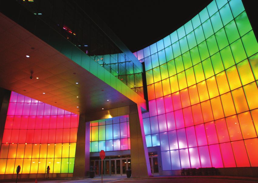
Transform Cityscapes with Energy-Efficient Light

                                                                         CN Tower
                                                                         Toronto, Canada

                                                                                                                       Photography Jerrold Litwinenko

                                                     Transforming the CN Tower
                                                     For nearly a decade, the 1,815 ft (553 m) CN Tower was minimally lit in an effort
                                                     to conserve energy while awaiting a better long-term lighting solution. Following
                                                     extensive evaluation, a Philips Color Kinetics lighting system was chosen to visually
                                                     transform the Tower’s appearance while also reducing energy consumption and
                                                     maintenance requirements. According to the CN Tower’s calculation, the entire LED
                                                     installation consumes 60% less energy than the fully illuminated Tower of the 1990s,
                                                     and 10% less energy than the previous system.

                                                     Lighting Control and Configuration
                                                     With its scalable design, Light System Manager offers the ideal controller solution
                                                     for the CN Tower project. Installed with standard Ethernet cabling and network
                                                     hardware, LSM manages the 1,300 high-performance lighting fixtures mounted within
                                                     the Tower’s elevator shafts and antenna tower.

                                                     What’s in a Light System Manager Light Show?
                                                     A light show is a set of digital instructions orchestrating how and when your lighting
                                                     installation displays effects. The CN Tower lighting design team created mood,
E For full details on using the software modules     interest, and visual impact by customizing the appearance and behavior of standard
to design your lighting installation, refer to the
Light System Manager user guide available at
                                                     Light System Composer effects with unique color palettes, sequences, and playback
www.philipscolorkinetics.com/ls/controllers/lsm/     zones. Additionally, via the show scheduling feature, specifically themed light shows
                                                     display automatically to coincide with national events and holidays.

                                                                                                        Light System Manager   Product Guide            3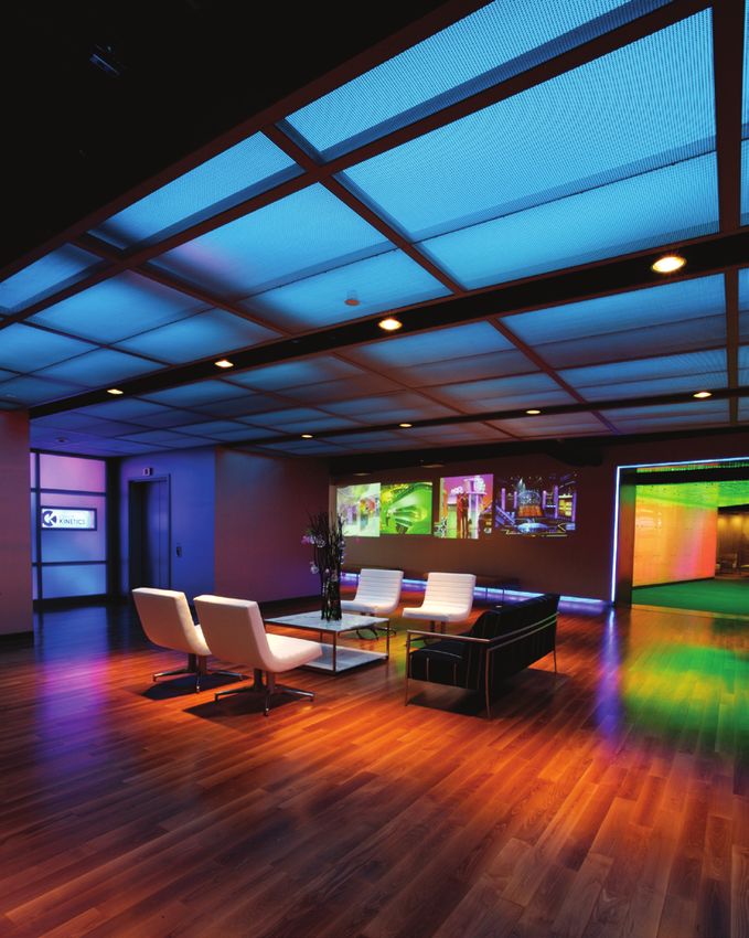
Light System Manager Environments

                                                                                                                        Costa Concordia
                                                                                                                        Genoa, Italy

                                                                                         Photography Piero Comparotto
Multi-zone Installation
Costa Concordia is the largest and most technologically advanced ship among Italy’s
Costa Cruise line fleet. The expansive ship features a visually striking interior with
a series of engaging environments highlighted by LED lighting fixtures from Philips
Color Kinetics.

With custom-designed chandeliers that resemble glowing, colorful sea urchins, the
main atrium dazzles passengers entering the Costa Concordia. The chandeliers are
illuminated by iColor MR g2 lamps, which fit most common MR16 fixtures. Moving
to the main lounge, passengers encounter a curved ceiling with diffused, linear
tubes enclosing flexible strands of iColor Flex SL. Each strand has 50 full-color
LED nodes that are individually controllable. The fixture configuration allows for
graphical patterns and color sequences to chase across the ceiling. Each successive
environment onboard the ship stands out for its unique visual appearance and
physical form.

Costa Cruise line selected Light System Manager as the lighting control solution for
the Costa Concordia. LSM offers a convenient and cost-effective control solution,
with zone control allowing simultaneous display of varied show content in separate
areas of the ship. The ship’s main atrium, main lounge, aft lounge, aft atrium, dance
lounge, “Tavernetta,” creative room, and spa each comprise a separately controlled
zone. Rather than requiring a separate DMX-based controller for each zone, the
entire installation is controlled from a central location by LSM.

For ease of installation, Light System Manager offers an Ethernet-based system
compatible with conventional network hardware. LSM’s support for up to 15,000
individually controllable LED nodes is an important factor for the Costa Concordia,
where each zone contains 1,250 or more LED nodes or fixtures.

4    Light System Manager   Product Guide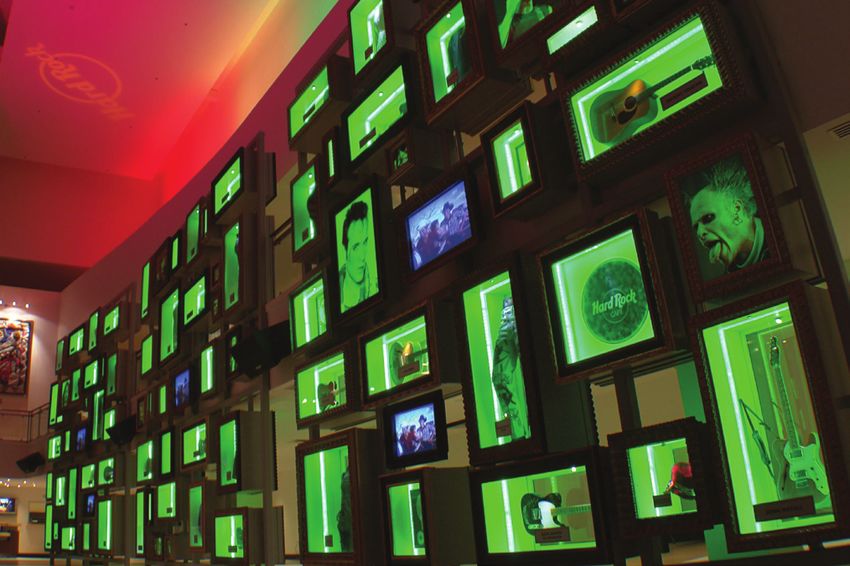
Architectural Exterior
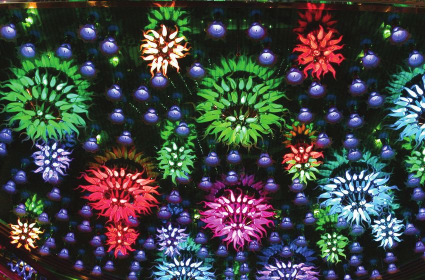
A popular Philadelphia landmark, Boathouse Row comprises twelve
boating clubs in ten architecturally distinct buildings along a half-mile
stretch of the Schuylkill River. The lighting system from Philips Color
Kinetics replaces a 30-year-old incandescent system that required frequent
and costly maintenance.
Like the CN Tower, Boathouse Row uses LED lighting to transform a
well-known but static exterior scene into an expressive canvas. The
lighting design team envisioned a primary display of white light with the
capability to punctuate the boathouses with vibrant color and visual effects
for special occasions. The designers accomplished their goal by creating
shows with the Show Designer module in Light System Composer. The
straightforward and easy-to-use software interface enabled the team to
Boathouse Row Photography Jacques-Jean Tiziou focus on the creative aspects of the project rather than configuration.
Philadelphia, Pennsylvania New users were able to program and submit light shows for conceptual
approval in a matter of minutes, with limited prior experience using Light
System Manager.
Architectural Interior
The restored Hard Rock Hotel & Casino Biloxi opened its doors on lucky
7.7.07 (July 7, 2007) after suffering extensive damage from Hurricane
Katrina. LSM’s scalable, Ethernet-based design proved critical to the
success of the complex project, which features intricate and varied designs
for the thousands of LED nodes and fixtures within the hotel. Light
System Manager’s compatibility with commonly used network components
allowed for reliable and seamless installation.
Light System Manager controls eight separate lighting zones, including
the Hard Rock Biloxi Memorabilia Wall, which pays homage to Rock and
Roll’s greatest influences. The fixtures from Philips Color Kinetics used
in the two story display feature zero ultraviolet and infrared emissions,
preventing damage to the display’s priceless contents.
Hard Rock Hotel & Casino Biloxi Photography Buddy Pope, 4Wall
Entertainment Lighting
Biloxi, Mississippi
Theater and Entertainment
The wave wall installed in the Georgia Aquarium’s central plaza is
150 x 25 ft (45.7 x 7.6 m) and comprises five curving bands of color-
changing light. The wave wall acts as an immersive visual centerpiece to
incoming visitors.
Additionally, the wall doubles as a 75 ft (22.9 m) wide projection surface
for video shows. For video presentation, the fixtures in the center of the
wall turn off, creating a white “video screen”, and the fixtures along the
perimeter of the wall remain on, creating a colorful frame surrounding the
presentation.
Georgia Aquarium Photography Kieran Reynolds Photography
Atlanta, Georgia
Light System Manager Product Guide 5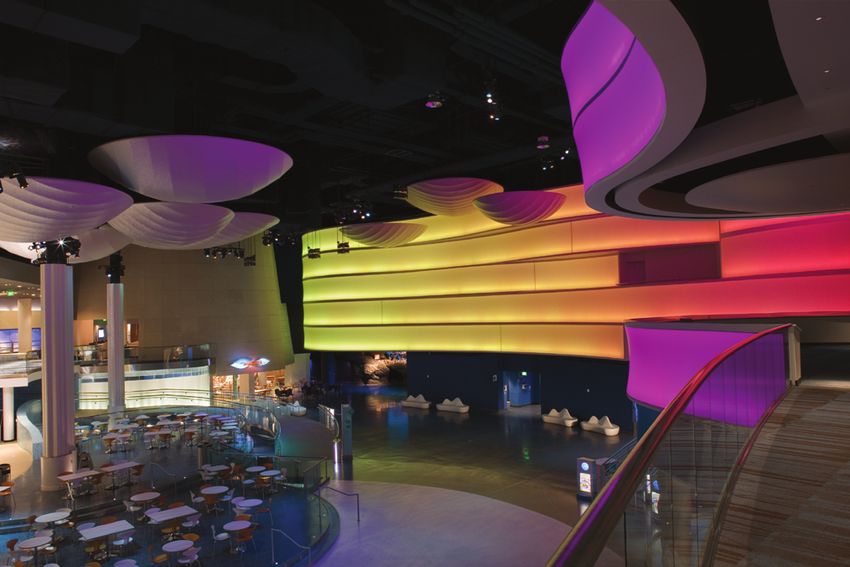
Specifications
Due to continuous improvements and innovations, specifications may change without notice.
Item Specification Details
Input Voltage 100 – 240 VAC, auto-switching
Electrical
9.5 in
Power Consumption 180 W max. 241 mm
Supported LED Nodes Up to 15,000 LED nodes
1.6 in
41 mm
Capability Network Data KiNET Ethernet protocol* via standard Ethernet switch†
11.8 in
Playback Output Light shows containing one or more visual effects 301 mm
Dimensions 10.6 in
9.1 x 11 x 3.5 in (230 x 280 x 88 mm) 270 mm
(Height x Width x Depth)
2.3 in
60 mm
Physical Weight 9.3 lb (4.2 kg)
11.9 in
Operating Temperature 32 – 95° F (0° – 35° C) 303 mm
10.2 in
260 mm
Operating Humidity 0 – 90%, relative humidity, non-condensing
Certification Certification UL / cUL, FCC, CE, C-Tick
and Safety Environment Indoor / Dry location
* KiNET is the Ethernet lighting protocol from Philips Color Kinetics.
† Use PoE (Power-over-Ethernet) switches, or PoE injectors, when installing a
lighting system containing one or more Ethernet Controller Keypads.
Software Requirements
System
Specification PC Mac
Requirements
Software Operating System Vista / Windows 7 Mac OS X 10.9 or greater
Optical Drive CD-ROM or DVD drive CD-ROM or DVD drive Included in the Box
Hardware Memory 256 MB RAM 256 MB RAM Light System Manager
Power cable
Disk space 10 MB free disk space 10 MB free disk space
(2) Mounting brackets and (6) Mounting screws
Software CD
Quick Start Guide
Installation Instructions
Light System Manager and Accessories
Item Item Number Philips 12NC Ethernet Controller Keypad
Light System Manager 103-000015-04 912400130174 Ethernet Controller Keypad is a wall-
mounted triggering device that controls
up to eight light shows and lighting fixture
brightness at the touch of a button.
Ethernet Controller Keypad 103-000023-00 910503700326
PoE Injector (North America Power Cord) 109-000029-00 910503700383 OFF
PoE Injector (Europe Power Cord) 109-000029-01 910503700384
AuxBox 103-000021-01 910503702433
Use Item Number when ordering in North America.
AUX BO
X AuxBox
AuxBox instantly activates up
8
7
6
US 5
STAT
4
3
2
to eight light shows using any
G̃
L PORT
TS SERIA
INPU
24 VDC
+/ -
remote triggering device with
a dry-contact closure.
6 Light System Manager Product Guide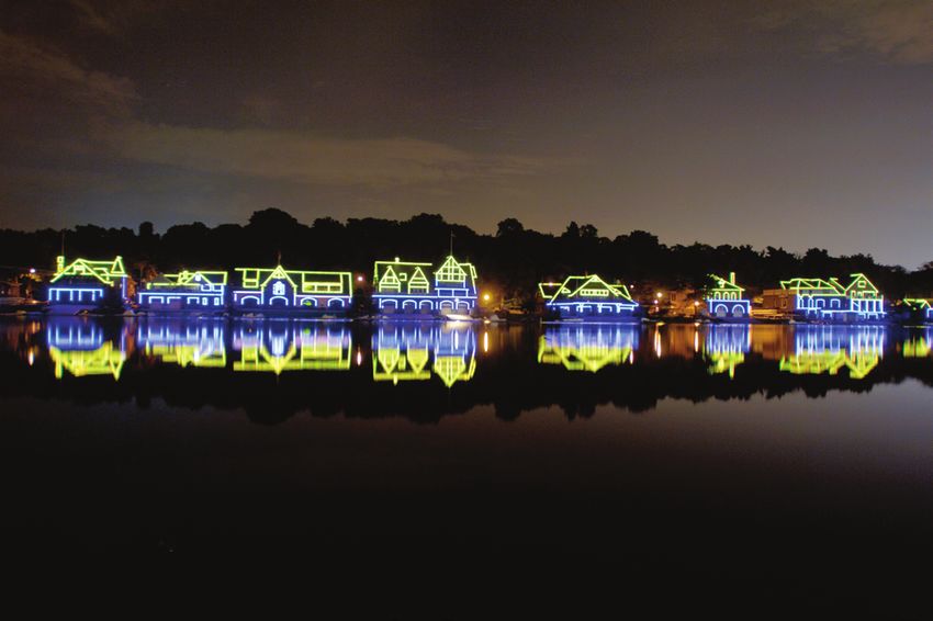
Configuration Overview
                                                                 Light System Manager allows your lighting installation to display of a variety of light show
                                                                 designs and choreographed moving images. LSM comprises Light System Engine, a computer
                                                                 (for initial setup and programming), one or more Ethernet Controller Keypads (optional),
                                                                 network hardware, and lighting components.

                                                    Ethernet
                                                    Controller
                                                     Keypads
                                                    (optional)                               Ethernet Switch

                                PC or
                                                                                      CA
                                 Mac                                                    T5
                                                                                          eC
                                                                                              able
       Light System
         Manager

                                                                                                                    ColorBlast Powercore
                                                                      Data Enabler                                        Fixtures
                                                                          Pro

                                                       100–240 VAC

                                                                 Ethernet Layout
                                                                 Light System Engine hardware communicates with the interfaces in the lighting installation
                                                                 (power / data supplies and Data Enabler Pro devices) via KiNET Ethernet, the network
                                                                 protocol engineered by Philips Color Kinetics for high-performance lighting system control.
                                                                 LSE offers full compatibility with all conventional Ethernet hardware, accommodating
                                                                 network trees up to three switches deep between the LSE and the farthest KiNET interface.
                                                                 Ethernet limits the maximum cable run to 328 ft (100 m). Adding Ethernet optical data
                                                                 cabling and hardware to your layout extends the maximum cable run distance.

E For optical device Ethernet network                            Ethernet Controller Keypads are PoE (Power over Ethernet) devices. U       se PoE-compatible
specifications, refer to your optical device user                Ethernet switches if Ethernet Controller Keypads are installed on the network.
documentation.                                                   Alternatively, if using non-PoE switches, install PoE injectors from Philips Color Kinetics
                                                                 inline between each keypad and switch.

                                                                 Dedicated Local Area Network
                                                                 To achieve optimal display and network connectivity performance, the LSE and all lighting
                                                                 components must be installed on a dedicated Local Area Network. Light System Engine
                                                                 hardware delivers thousands of packets of light output data per second to your lighting
                                                                 installation, requiring uninterrupted data throughput.

                                                                 Automatic Interface Discovery and Creating Maps
                                                                 Light System Engine references a map file when communicating with the lighting components
                                                                 in the network. The map allows the LSE to identify every fixture and interface in the
                                                                 installation as a separate device and route data accordingly. For your convenience, the
                                                                 Management Tool module in Light System Composer automatically discovers all connected
                                                                 Ethernet interfaces and fixtures, including their IP addresses and device names.

                                                                                                                           Light System Manager   Product Guide   7
Prepare for the Installation
Owner / User Responsibilities
It is the responsibility of the contractor, installer, purchaser, owner, and user to
install, maintain, and operate the Light System Manager system in such a manner as
to comply with all applicable codes, state and local laws, ordinances, and regulations.
Consult with an appropriate electrical inspector to ensure compliance.

Planning the Installation
Philips Color Kinetics offers lighting systems suitable for environments ranging
from the simplest to the most complex. A simple LSM installation might use 25
ColorGraze Powercore fixtures installed in a single zone, whereas a larger LSM
installation might use 200 strands of iColor Flex SLX displaying light shows in
multiple zones. Regardless of the size and complexity of your project, the time you
spend up front can help minimize installation and configuration issues. Keep these
suggestions in mind as you plan your installation:

1. Create a lighting design (CAD layout, architectural plan, or other diagram) that
   specifies the locations of all lighting fixtures, power / data supplies, Data Enabler
   Pro devices, Ethernet switches, Ethernet cables, the Light System Engine, and
                                                                                           E Product Guides are available online at
   Ethernet Controller Keypads.                                                            www.philipscolorkinetics.com/support/
2. Use the online Configuration Calculator, and the appropriate Product Guides             productguides/
   and wiring diagrams, to determine the number of fixtures each circuit in your           E The Configuration Calculator is available
   installation can support, based on type of fixture, power source, line voltage,         online at www.philipscolorkinetics.com/support/
                                                                                           install_tool/
   circuit load, and cable lengths.
3. Light System Manager is an Ethernet-based system offering flexible and convenient
                                                                                           E For detailed optical device Ethernet network
   installation options. Note that Ethernet limits maximum individual cable runs to        specifications and installation steps, refer to your
   328 ft (100 m). For larger installations, adding Ethernet optical data cabling and      optical device user documentation.
   hardware to your lighting network extends the maximum cable run distance.
4. As part of the lighting design plan, where possible, make use of a repeated layout
   that specifies the preferred orientation of each fixture. For example, if using
   iColor Tile MX fixtures, install each fixture in a uniform manner so that jumper
   cables plug into the same side of each fixture in a sequence.
5. The Management Tool module in Light System Composer automatically discovers
                                                                                           E The Addressing and Configuration Guide and
   all connected Ethernet power /data supplies, Data Enabler Pro devices, and
                                                                                           QuickPlay Pro software download are available at
   addressable fixtures. As needed, use QuickPlay Pro addressing and configuration         www.philipscolorkinetics.com/support/addressing/
   software to assign unique IP addresses and device names to all power / data
   supplies, Data Enabler Pro devices, and addressable fixtures before using the
   Management Tool to map your installation.
6. To streamline physical installation and future maintenance, affix a weatherproof
   label identifying installation placement, IP address, and device name to an
   inconspicuous location on each power / data supply, Data Enabler Pro, and fixture
   housing.
7. Refer to the Light System Manager User Guide for instructions on using the
   modules in Light System Composer to map your installation, design light shows,          E The Light System Manager User Guide is
   configure and upload files to the LSE, and set playback parameters. The Light           available online at www.philipscolorkinetics.com/
                                                                                           ls/controllers/lsm/
   System Manager User Guide also contains a tutorial section.

8    Light System Manager   Product Guide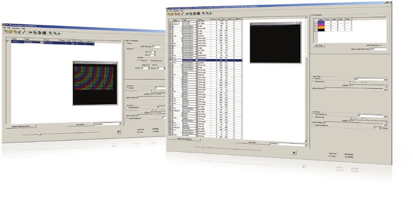
Start the Installation
1. Install all lighting fixtures, power / data supplies, and Data Enabler Pro devices. If
   your installation calls for jumper cables to add space between fixtures, make sure
   they are available.
2. Verify that your LSE is installed on a dedicated LAN using standard Ethernet
   switches.
3. If using one or more Ethernet Controller Keypads, you must use a PoE (Power
   over Ethernet) switch, or install PoE injectors inline between each keypad and the
   switch to which it is connected.

Install Light System Manager
Light System Manager comprises two components: the Light System Engine controller
and Light System Composer software:

LSE Installation Overview
• Install LSE in a convenient, temperature-controlled location. Use the Installation
  Instructions document included in the product packaging for step-by-step
  hardware installation instructions.
• Both LSE and the personal computer hosting LSC must be set up on a dedicated
  local area network.
• LSE automatically assigns an IP address to the personal computer on your
  dedicated network. After connecting the personal computer, verify that the
  computer can connect to the LSE. Note that following light show programming
  and configuration, you can disconnect and remove the personal computer from
  the network.
• Refer to the Light System Manager User Guide for network troubleshooting
  techniques, as needed. The Light System Manager User Guide is available online at
  www.colorkinetics.com/ls/controllers/lsm/.

LSC Installation Overview
• Use the Light System Manager Quick Start Guide included in the product
  packaging for step-by-step software installation instructions.
• Install LSC software from the CD included in the product packaging or by
  downloading it from www.colorkinetics.com/ls/controllers/lsm.

Using the Light System Engine Interface
The LSE has a web-based interface for setting system time (used for accurate
playback scheduling) and obtaining log files. Connect to the LSE interface by entering
10.1.3.100 in a web browser on the computer connected to the dedicated local
area network. To access the System Time screen, enter a login of lse and a password
of lse.

Light show and configuration files are stored on the LSE hard drive, enabling you to
disconnect the personal computer on the lighting network once setup is complete.
However, to perform live light show playback or change the light show files stored on
the LSE, you must reconnect the personal computer. You can store hundreds of light
shows on the LSE hard drive.

                                                     Light System Manager   Product Guide   9
About Light System Composer Software                                                        Management Tool
Light System Composer is a full-featured software package containing the following
modules:

Management Tool — When connected to a lighting network, the Management Tool
module automatically discovers all lighting system components, allowing you to create
a map of the installation. The map identifies all hardware so that the LSE controller
can send accurate light output instructions. Additionally, the map allows you to create
groups of fixtures to simplify playback control.

Show Designer — The Show Designer module enables you to author and refine light
shows using eight fixed color and chasing color effects, two animated image effects, and
two geometric effects. You can apply pre-defined effects to fixtures, and then modify
                                                                                            Show Designer
those effects by modifying their parameters. Show Designer also allows you to simulate
your show via the Live Play simulation feature, which displays the light shows on the
fixtures in your installation.

Config Maker — The Config Maker module provides an interface to program
playback zones, schedule show playback, and set triggers for external triggering devices,
such as the Ethernet Controller Keypad. Once configuration is complete, the Config
Maker module uploads your config file to the LSE for storage and playback.

Playback Control — Use the Playback Control module to trigger light shows
from a computer on the lighting network, or pause and refresh LSE playback. The
Playback Control module also allows you to view scheduled events and access system
information.

                                                                                            Config Maker

Workflow: Creating and Displaying a Light Show
1. Create a Map
The first step in creating a light show is to map the installation. The map links all
lighting fixtures and interfaces (power / data supplies and Data Enablers) to the LSE
controller, and acts as a virtual representation of the installation. The Management Tool
module enables you to automatically discover all lighting system components and build
the map. When new fixtures are added to an existing installation, or when working off
site, the Management Tool module also allows you to manually build a fully functional
virtual map.
2. Create a Light Show
When the map is completed, the next step is to create a light show with one or more
effects. The Show Designer module lets you add effects to each group of fixtures in the     Playback Control
installation and then modify the effect parameters to create unique results. Use the Live
Play feature to test and refine your show.

3. Set Triggers, Create Zones, and Download Files
When you have built a map and designed a light show, the next step is to configure
playback schedules, playback zones, and keypad triggering in the Config Maker module.
Once you have created configurations, associate them with a map file and show file,
then upload to the LSE.

4. Playback Control
Once you have uploaded all files to the LSE, the LSE will automatically play back the
show files based on the scheduling you configured with the Config Maker module. You
can use the Playback Control module to override automated scheduling and trigger
on-demand light shows from a computer on the lighting network.

10   Light System Manager   Product Guide
Light System Manager Effects Palette
Welcome Wall at the Potawatomi Bingo Casino Photography Marty Peck,
Creative Lighting Design & Engineering
Milwaukee, Wisconsin
The Light System Composer Show Designer module offers a palette of fourteen
pre-defined visual effects:
Animation Sparkle
A series of still images appears in When applied to a group of fixtures,
rapid succession, creating an animation flashes of light appears on several
sequence. fixtures in the group, in random order.
Chasing Rainbow Streak
When applied to a group of fixtures, When applied to a group of fixtures,
colors of the rainbow appear to chase a pulse of color races from fixture to
each other from fixture to fixture. fixture.
Color Sweep XY-Burst
When applied to a group of fixtures, Produces multiple expanding concentric
a color advances from fixture to fixture circles of color.
in a sweeping motion.
XY-Spiral
Cross Fade Produces a color-changing wheel
Colors fade gracefully from a solid color revolving around a center point.
to another solid color. White Cross Fade
Custom Rainbow Produces white light that fades between
Custom Rainbow is similar to Chasing a start color temperature and intensity
Rainbow, but allows a choice of colors. and an end color temperature and
intensity (for use with IntelliWhite
Fixed Color fixtures).
Static display of a single color.
White Fixed Color
Image Scroll Produces a static display of a user-
A still image moves across the fixtures in specified fixed color temperature and
a user-defined motion. intensity (for use with IntelliWhite
Random Color fixtures).
At specified intervals, colors jump cut
from one color to the next, in random
order.
Light System Manager Product Guide 11Light System Manager On Display
Headquartered in Burlington, Massachusetts, Philips Color Kinetics is a global LED
lighting innovation and product design center for Philips. The 50,000 square ft (4,645
square m) office, laboratory, and showroom space utilizes LED lighting technology
throughout. Light System Manager manages the LED lighting zones in the building,
including the lobby, conference rooms, work spaces, exterior signage, and product
demonstration areas.
Lighting Zone Details
The lobby space features subtly animated light shows displayed on both RGB and white
LED lighting systems. 20 unique shows ranging in duration from 10 minutes to 12 hours
gently scroll across the ceiling, wall surfaces, and alcoves. Additionally, the fixtures
installed directly above the reception desk are controlled by LSM as a separate region
within the lobby zone, allowing for warm white illumination focused on the receptionist
work space and visitor seating area, as needed.
How it Works
LSM uses two-dimensional maps to identify and control the lighting components in each
lighting zone. The lobby map, for example, contains four rectangular clusters of fixtures,
varying in size. The large rectangular area corresponds to the main ceiling, and the
smaller rectangular areas match the wall adjacent to the elevator, the ceiling adjacent to
the elevator, and the wall behind the reception desk.
Philips Color Kinetics
Headquarters and Showroom
0 seconds 60 120 180 240 300 360 420 480 540 600
Image Scroll Effect
The lobby map allows LSM to accurately display light shows according to the position of
each fixture. Based on a schedule, LSM continuously scrolls images (.BMP, .JPG) across
the lobby map, creating a seamless animated effect. Because each image is configured to
be larger than the map dimensions, only a portion of the image is displayed at any given
time.
Playback Controls
Once set up, the LSM functions as a standalone device that automatically displays one
or more scheduled light shows in each lighting zone. The lobby schedule calls for unique
shows each day of the week and on certain holidays. Additionally, Ethernet Controller
Keypads installed in multiple locations allow users to override a scheduled lobby show at
the touch of a button and select from eight additional choices.
Philips Color Kinetics Copyright © 2009 – 2015 Philips Solid-State Lighting Solutions, Inc. All rights reserved.
Chromacore, Chromasic, CK, the CK logo, Color Kinetics, the Color Kinetics logo, ColorBlast,
3 Burlington Woods Drive ColorBlaze, ColorBurst, eW Fuse, ColorGraze, ColorPlay, ColorReach, iW Reach, eW Reach,
Burlington, Massachusetts 01803 USA DIMand, EssentialWhite, eW, iColor, iColor Cove, IntelliWhite, iW, iPlayer, Optibin, and Powercore
Tel 888.385.5742 are either registered trademarks or trademarks of Philips Solid-State Lighting Solutions, Inc. in
the United States and / or other countries. All other brand or product names are trademarks
Tel 617.423.9999 or registered trademarks of their respective owners. Due to continuous improvements and
Fax 617.423.9998 innovations, specifications may change without notice.
www.philipscolorkinetics.com CN Tower cover photograph by George Fischer DAS-000035-00 R08 05-15You can also read