TCS 037 - 2019 The Supply of Electronic Speed Limit Signs - January 2019 - VicRoads
←
→
Page content transcription
If your browser does not render page correctly, please read the page content below
TCS 037 - 2019

Specification for

The Supply of

Electronic Speed Limit Signs

January 2019
Rev A

 Page 1 of 36

TCS 037 - 2019                                           Rev A

     TCS 037 – 2018

                                                           Foreword

                                                           This specification has been developed by VicRoads. It is
                                                           one of a number of technical specifications, and
                                                           associated standard drawings, which set out the
                                                           requirements for roadside ITS devices, traffic signal
                                                           equipment and other electrical equipment and associated
                                                           devices and control systems.

                                                           This specification is intended for use in all relevant
                                                           works undertaken by or on behalf of VicRoads.

                                                           VicRoads Standard Drawings, Specifications and
                                                           Guidelines are available for downloading from VicRoads
                                                           website at the following address
                                                           https://www.vicroads.vic.gov.au/business-and-
                                                           industry/technical-publications/electrical-and-intelligent-
                                                           transport-systems

     COPYRIGHT
                                                           Specification updates. VicRoads specifications and
     © Road Corporation trading as VicRoads. All           associated standard drawings are subject to periodic
     rights reserved.                                      review. To keep the specifications up to date,
                                                           amendments or new editions are issued as necessary. It
     This document remains the property of VicRoads.       is therefore important for users of VicRoads
     No part of this document may be reproduced or         specifications to ensure that they have the latest version
     copied in any form or by any means, electronic or     and associated amendments.
     mechanical, including photocopying, without the
     written permission of VicRoads
                                                           Smart Journey Systems
                                                           60 Denmark Street Kew 3101

                                                           Email:hercegd@roads.vic.gov.au

Page 2 of 36                                 Electronic Speed Limit Signs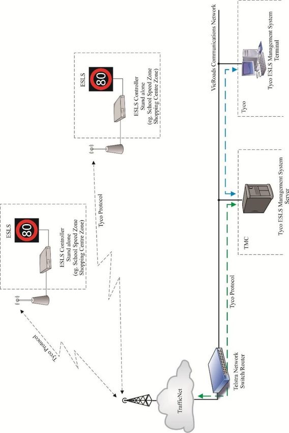
Rev A                                  TCS 037 - 2019

                                    PREFACE

A. TELECOMMUNICATIONS EQUIPMENT

A.1   All telecommunications equipment shall comply with relevant requirements of the Australian
      Communications and Media Authority (ACMA). Such equipment shall be labelled with a
      Regulatory Compliance Mark.

B. CHANGES TO THIS SPECIFICATION

B.1   The main changes to this specification from the previous version are listed below:

      •       Addition of proposed new ESLS Network Monitoring and Control System
      •       Addition of Side Road Activated Speed (SRAS) system

                                      Electronic Speed Limit Signs                         Page 3 of 36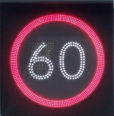
TCS 037 - 2019                                     Rev A

                                            Revision History

Version Revision             Date              Author                         Description
                                                               Amendment to existing specification
                                                               Incorporate Network Monitoring and Control
 2019            A        January 2019            SJS          System
                                                               Incorporate Side Road Activated Speed
                                                               (SRAS) system
                                                               Incorporate AS 5156, AS 4509.2, AS 4086.1 &
 2014            A       December 2014            SJS          AS 4086.2
                                                               Incorporate Tyco ESLS Management System

 2004            7        January 2004      VicRoads ITS       Amendment to existing specification

 2003            6         June 2003        VicRoads ITS       Amendment to existing specification

 2001            5       September 2001     VicRoads ITS       Amendment to existing specification

 2001          2,3 & 4                      VicRoads ITS       Not released

 2001            1         April 2001       VicRoads ITS       New specification

Page 4 of 36                             Electronic Speed Limit Signs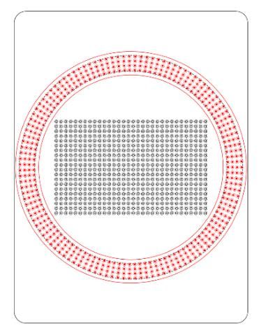
Rev A                                                       TCS 037 - 2019

                                                    Contents
SECTION 1         SCOPE AND GENERAL .............................................................................. 7
 1.1   SCOPE .................................................................................................................................... 7
 1.2   GENERAL .............................................................................................................................. 7
 1.3   INTELLECTUAL PROPERTY ............................................................................................. 8
 1.4   ACRONYMS .......................................................................................................................... 9

SECTION 2         RELATED SPECIFICATIONS AND DRAWINGS ................................ 10
 2.1   AUSTRALIAN STANDARDS ............................................................................................ 10
 2.2   VICROADS SPECIFICATIONS AND DRAWINGS ......................................................... 11
 2.3   ADDITIONAL SPECIFICATIONS AND DRAWINGS ..................................................... 11
 2.4   EXCEPTIONS AND CLARIFICATIONS TO AS 5156–2010 ........................................... 12

SECTION 3         OPERATION AND CONTROL ................................................................. 14
 3.1   GENERAL ............................................................................................................................ 14
 3.2   NETWORK MONITORING AND CONTROL SYSTEM .................................................. 14
 3.3   ESLS NETWORK MANAGEMENT SYSTEM .................................................................. 14
 3.4   SIDE ROAD ACTIVATED SPEED .................................................................................... 15
 3.5   DISPLAY CHANGES DUE TO EXTERNAL SWITCH INPUTS ..................................... 15
 3.6   STREAMS OPERATION..................................................................................................... 15
 3.7   SYNCHRONISATION OF SIGNS ...................................................................................... 15
 3.8   MONITORING ..................................................................................................................... 16
 3.9   LOGGING ............................................................................................................................ 16

SECTION 4         MECHANICAL REQUIREMENTS .......................................................... 17
 4.1   GENERAL ............................................................................................................................ 17
 4.2   SIGN MOUNTING .............................................................................................................. 17
 4.3   FACILITY SWITCH ............................................................................................................ 18

SECTION 5         DISPLAY AND OPTICAL REQUIREMENTS........................................ 19
 5.1   GENERAL ............................................................................................................................ 19
 5.2   OPTICAL REQUIREMENTS .............................................................................................. 20
 5.3   DISPLAY – DISCRETE NUMERALS ................................................................................ 20
 5.4   DISPLAY – MATRIX .......................................................................................................... 21
 5.5   DISPLAY – ANNULUS ....................................................................................................... 21

SECTION 6         ELECTRICAL REQUIREMENTS ........................................................... 23
 6.1   GENERAL ............................................................................................................................ 23
 6.2   SOLAR POWER .................................................................................................................. 23
 6.3   MAINS POWER ................................................................................................................... 24
 6.4   BATTERY BACKUP ........................................................................................................... 24
 6.5   ELECTROMAGNETIC COMPLIANCE (EMC) ................................................................ 25

SECTION 7         MARKINGS AND DOCUMENTATION .................................................. 26
 7.1   MARKINGS ......................................................................................................................... 26
 7.2   DOCUMENTATION ........................................................................................................... 26

APPENDIX A            NETWORK MANAGEMENT SYSTEM .............................................. 27

                                                    Electronic Speed Limit Signs                                                 Page 5 of 36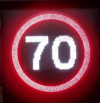
TCS 037 - 2019                                                    Rev A

 A1       GENERAL ............................................................................................................................ 27
 A2       PROTOCOLS ....................................................................................................................... 27

APPENDIX B              NETWORK MONITORING AND CONTROL SYSTEM .................. 28
 B1       GENERAL ............................................................................................................................ 28
 B2       PROTOCOLS ....................................................................................................................... 28

APPENDIX C              VICROADS ITS PLATFORM................................................................ 29
 C1       GENERAL ............................................................................................................................ 29
 C2       FIELD PROCESSOR ........................................................................................................... 29
 C3       COMPLIANCE WITH STREAMS ...................................................................................... 29
 C4       SPECTRUM NETWORK MANAGEMENT SYSTEM ...................................................... 30

APPENDIX D              FAULT NOTIFICATIONS AND LOGGING ....................................... 31
 D1       MINIMUM REQUIRED FAULT NOTIFICATIONS ......................................................... 31
 D2       MINIMUM LOGGING REQUIREMENTS ........................................................................ 32

APPENDIX E              GUIDELINES FOR PURCHASING AND INSTALLATION ............ 34
 E1       DETAILS TO BE INCLUDED WHEN TENDERING ....................................................... 34

APPENDIX F              REQUIREMENTS FOR TYPE APPROVAL ....................................... 35
 F1       GENERAL ............................................................................................................................ 35
 F2       REQUIRED NATA ACCREDITED TESTING .................................................................. 35
 F3       COMPATIBILITY WITH NMCS ........................................................................................ 35
 F4       COMPATIBILITY WITH NMS .......................................................................................... 35
 F5       COMPATIBILITY WITH STREAMS ................................................................................. 36
 F6       OTHER REQUIRED INFORMATION ............................................................................... 36
 F7       ASSESSMENT PROCEDURE ............................................................................................ 36
 F8       TYPE APPROVAL .............................................................................................................. 36

Page 6 of 36                                         Electronic Speed Limit Signs
Rev A                                    TCS 037 - 2019

                   SECTION 1                SCOPE AND GENERAL

1.1     SCOPE

1.1.1   This specification covers the design, manufacture and operation of Electronic Speed Limit
        Signs (ESLS) intended for use as school speed zone, strip shopping centre and Side Road
        Activated Speed (SRAS) treatments.
1.1.2   This specification is not intended to cover the requirements of ESLS used as part of Lane Use
        Management Systems (LUMS). The requirements for Lane Use Signs (LUS) are outside the
        scope of this specification.

1.2     GENERAL

1.2.1   ESLS are used to display a legally enforceable speed limit to be adopted at different times. Any
        reference to “sign” within this document shall be taken to mean “Electronic Speed Limit Sign”.
1.2.2   Typical versions of the ESLS are:
        •   Single Speed – a single speed limit display at specified times and is blank at other times.
            Typically used for time-based school speed zones and Side Road Activated Speed.
        •   Dual Speed – can display two different speed limits. Typically used for time-based
            shopping strip speed zones or school zones that display the default speed limit.
        •   Multiple Speed – capable of displaying three or more speed limits.

1.2.3   The creation of the numeral be by either discrete character or matrix panel. Where supported
        by the operating and control system, the use of a matrix panel shall be used, otherwise a discrete
        panel may be employed and used. See Figures 1.1 and 1.2 below.

                   Annulus                                              Discrete
                                                                        characters

                           Figure 1.1 – Typical discrete character ESLS

                                         Electronic Speed Limit Signs                         Page 7 of 36
TCS 037 - 2019 Rev A
Matrix
panel
Figure 1.2 – Typical matrix ESLS
1.2.4 Individual tender documents shall detail the types of signs required for a specific project.
1.2.5 The sign display shall be made up of point light sources, arranged in accordance with this
specification to comprise a clear and enforceable speed limit sign.
1.2.6 Signs are to be designed and constructed to conform to AS 5156 except where modified to meet
the requirements stated in this document. Details of the exceptions and clarifications from AS
5156 are given in Section 2.4.
1.2.7 Conspicuity devices as described in AS 5156 shall not be used.
1.2.8 All ESLS shall be VicRoads Type Approved as detailed in APPENDIX F.
1.3 INTELLECTUAL PROPERTY
1.3.1 In relation to all Intellectual Property used in/or to operate the system, the contractor grants to
VicRoads non exclusive licence to “use, modify and/or sell” or do anything else that without
the licence, could be breach of the licensors Intellectual Property.
1Intellectual Property shall include, but not be limited to, the following:
• Software.
• Source code(s).
• Schematic diagrams.
• Circuit diagrams.
• Wiring diagrams.
• Listings of components and sub-components.
• Any and all operational and maintenance documentation.
Page 8 of 36 Electronic Speed Limit SignsRev A TCS 037 - 2019
1.4 ACRONYMS
The acronyms used in this document shall be interpreted as follows:
ACMA Australian Communications and Media Authority
AS Australian Standard
CLI Command Line Interface
ELV Extra Low Voltage
EMC Electromagnetic Compatibility
ESLS Electronic Speed Limit Sign
FP Field Processor
GPS Global Positioning System
GNSS Global Navigation Satellite System
HTTPS Hypertext Transfer Protocol Secure
ICMP Internet Control Message Protocol
IP Ingress Protection (degree of protection)
ITS Intelligent Transport System
LED Light Emitting Diode
NMCS Network Management and Control System
NMS Network Management System
NTP Network Time Protocol
NZS New Zealand Standard
RCD Residual Current Device
RMS Roads and Maritime Services (NSW)
SNMP Simple Network Management Protocol
SSH Secure Shell
SSL Secure Sockets Layer
SRAS Side Road Activated Speed
STREAMS An ITS communications/control platform used by VicRoads to
manage traffic operations on freeways
TCP/IP Transmission Control Protocol/Internet Protocol
TLS Transport Layer Security
UTC Coordinated Universal Time
Electronic Speed Limit Signs Page 9 of 36TCS 037 - 2019 Rev A
SECTION 2 RELATED SPECIFICATIONS AND
DRAWINGS
2.1 AUSTRALIAN STANDARDS
2.1.1 The fabrication and supply of all components shall conform to all relevant Australian Standards.
2.1.2 Where no specific reference is made to an Australian Standard, the materials and processes
used shall conform to the relevant Australian Standard or generally accepted practice.
2.1.3 The following related Australian Standards are referenced:
AS 1742.2 Manual of Uniform Traffic Control Devices, Part 2, Traffic
Control Devices for General use
AS 1743 Road signs - Specifications
AS/NZS 3000 Wiring Rules
AS 4086.1 Secondary batteries for use with stand-alone power systems
- General requirements
AS 4086.2 Secondary batteries for use with stand-alone power systems
- Installation and maintenance
AS/NZS 4509.2 Stand-alone power systems - System design
AS 5156 Electronic speed limit signs
AS 60529 Degrees of protection provided by enclosures (IP code).
AS IEC 62619 Secondary cells and batteries containing alkaline or other
non-acid electrolytes — Safety requirements for secondary
lithium cells and batteries, for use in industrial applications
AS/NZS 61000.6.1 General Standards – Immunity for residential, commercial
and light industrial environments
AS/NZS 61000.6.3 General Standards – Emission standard for residential,
commercial and light industrial environments
Page 10 of 36 Electronic Speed Limit SignsRev A TCS 037 - 2019
2.2 VICROADS SPECIFICATIONS AND DRAWINGS
2.2.1 All installation works shall conform to the relevant VicRoads specifications and related
specifications and standards as indicated throughout this document.
2.2.2 The fabrication and supply of all components shall conform to the relevant VicRoads
specifications, and related specifications and standards, as indicated throughout this document.
2.2.3 The following VicRoads documents are referenced:
Standard Contract Traffic Signal installation
Section 730
TCG 016 Product Compliance Process for ITS and Electrical
Products
TCS 060 VicRoads Extensions to RTA Protocol for Roadside
Devices
TCS 071 The Supply of Side Road Activated Speed (SRAS)
2.3 ADDITIONAL SPECIFICATIONS AND DRAWINGS
2.3.1 The fabrication and supply of all components shall conform to the following specifications and
drawings as indicated throughout this document.
Electronic Speed Limit Signs Page 11 of 36TCS 037 - 2019 Rev A
2.4 EXCEPTIONS AND CLARIFICATIONS TO AS 5156–2010
2.4.1 The following changes or clarifications to AS 5156 are summarised in Table 2.1 below:
AS 5156 Description Exception / Clarification
Clause
2.1.1.7 Conspicuity devices Clause does not apply
2.1.2.2 Pixel arrangement - Annulus Refer to this specification Section 5.5
2.1.2.3 Pixel arrangement - Matrix display signs Refer to this specification Section 5.4
2.1.2.4 Pixel arrangement - Discrete character Refer to this specification Section 5.3
signs
2.1.2.5 Pixel arrangement - Annulus display Refer to this specification Section 5.5
3.2.1 Product host control system Refer to this specification Section 3
3.2.2 Facility switch Refer to this specification Section 4.3
3.3 Remote control Refer to this specification Section 3
3.4 Programming Refer to this specification Section 5.4 &
Section 3
3.5 Communication protocol Refer to this specification Section 3
3.6 Monitoring, fault logging and reporting Refer to this specification Section 3
3.7 Fall-back operation Refer to this specification Section 3
4.1.1 Mechanical requirements - General Refer to this specification Section 4.1
4.1.2 Mechanical requirements - Sign Clause (g) does not apply
enclosure
4.1.3 Mechanical requirements - Sign Refer to this specification Section 4.2
mounting facilities
4.1.4.1 Control housing - Construction and Clause does not apply
positioning
4.1.4.2 Control housing - Anti-vandalism Clause does not apply
measures
4.1.4.3 Control housing - Power and Clause does not apply
communication equipment
4.1.5.1 Facility switch - General Refer to this specification Section 4.3
4.1.5.2 Facility switch - Control housing Refer to this specification Section 4.3
4.1.5.3 Facility switch - Type and rating Refer to this specification Section 4.3
4.1.5.4 Facility switch - Mounting Refer to this specification Section 4.3
4.1.5.5 Facility switch - Marking Refer to this specification Section 4.3
4.2.2 Operating voltage Refer to this specification Section 6.1
4.2.3 Battery backup Refer to this specification Section 6.4
4.4 Solar power Refer to this specification Section 6.2
4.6 Real-time clock Refer to this specification Section 3
Appendix B Display changes due to external switch Refer to this specification Section 3.5
- B2.3 inputs
Appendix B Graphics requirements Clause does not apply
- B2.4
Appendix B Graphics requirements Clause does not apply
- B4.1
Appendix B Message numbering for speed displays Refer to VicRoads specification for
- B4.2 extensions to RTA protocol for roadside
devices TCS 060
Appendix B Frame numbering for other displays Clause does not apply
- B4.3
Appendix B Message numbering for other displays Clause does not apply
- B4.4
Appendix B Standard bitmap display images Information only. Alternate image
- B4.5 definitions may be considered.
Page 12 of 36 Electronic Speed Limit SignsRev A TCS 037 - 2019
Appendix B Bitmap definitions for other displays Clause does not apply
- B4.6 .
Appendix D Wireless communications Clause does not apply
Table 2.1 - Exceptions and Clarifications to AS 5156
Electronic Speed Limit Signs Page 13 of 36TCS 037 - 2019 Rev A
SECTION 3 OPERATION AND CONTROL
3.1 GENERAL
3.1.1 Individual ESLS shall typically operate as an autonomous device.
3.1.2 Pairs of adjacent ESLS shall operate as a master/slave arrangement.
3.1.3 The sign operation and management system shall be one of the following:
• VicRoads Network Monitoring and Control System (NMCS). This is still to be specified;
• ESLS Network Management System Version 2 (NMS V2). This system operates speed
changes via a calendar uploaded into the sign;
• Side Road Activated Speed (SRAS). This system is a standalone operation activated by
vehicles approaching from the side road; or
• STREAMS (Possible future application).
3.1.4 The selection of the type of operation and management system shall be defined in individual
tender documents.
3.1.5 In the event of a major system failure the sign shall default to a blank display as specified in
AS 5156 Clause 3.7.
3.1.6 Unless otherwise specified in individual tender documents, communications between the
management system and each sign shall be via a 3/4G mobile data connection.
3.1.7 Master / Slave pairs of signs shall employ a single data connection.
3.1.8 Accuracy of the internal time clock to ensure synchronisation of signs shall be via Global
Navigation Satellite System (GNSS) as specified in Clause 3.7 below.
3.1.9 For signs operating via a calendar, if no calendar is present in the sign, it shall blank in
accordance with Clause 3.1.5 above, this is not applicable for SRAS treatment.
3.2 NETWORK MONITORING AND CONTROL SYSTEM
3.2.1 Where specified in the contract documents, the signs shall be designed for monitoring and
control through the VicRoads Network Monitoring and Control System (NMCS)
3.2.2 Signs connected to the NMCS shall use the protocols detailed in APPENDIX B.
3.2.3 Signs designed to operate on the NMCS shall be fully compliant and compatible, and shall
obtain a compliance certificate prior to supply. See APPENDIX F, Requirements for Type
Approval.
3.3 ESLS NETWORK MANAGEMENT SYSTEM
3.3.1 Where specified in the contract documents, the signs shall be designed for monitoring and
control through the VicRoads Network Management System (NMS) for ESLS.
3.3.2 Signs connected to the NMS shall use the protocols detailed in APPENDIX A.
Page 14 of 36 Electronic Speed Limit SignsRev A TCS 037 - 2019
3.3.3 Signs designed to operate on the NMS shall be fully compliant and compatible, and shall obtain
a compliance certificate prior to supply. See APPENDIX F, Requirements for Type Approval
3.4 SIDE ROAD ACTIVATED SPEED
3.4.1 Where specified in the contract documents, the signs shall be designed for monitoring and
control through a Side Road Activated Speed (SRAS) system.
3.4.2 Control and interfacing of the ESLS shall be as specified in TCS 071.
3.4.3 Monitoring and/or control through SRAS shall not eliminate the option of concurrent
monitoring and/or control through another system listed in clause 3.1.3 above.
3.5 DISPLAY CHANGES DUE TO EXTERNAL SWITCH INPUTS
3.5.1 Where specified in the contract documents, the signs shall be designed for monitoring and
control through external switch inputs. This will typically be for SRAS operation.
3.5.2 Where external switch inputs are used they shall, at minimum, comply with Clause B2.3 of AS
5156.
3.5.3 Where external switch inputs are used, additional open collector outputs shall be provided in
equal number to the inputs.
3.5.4 When an external switch is activated, and the respective message is displayed, the sign shall
activate the corresponding output to notify of successful operation.
3.5.5 Outputs shall remain active while the respective message is being displayed, unless a critical
fault occurs within the sign.
3.6 STREAMS OPERATION
3.6.1 In the future, VicRoads may move to the STREAMS platform for Electronic Speed Limit Signs.
See APPENDIX C for an overview of the STREAMS platform.
3.6.2 Signs designed to operate on the STREAMS platform shall be fully compliant and compatible
with STREAMS.
3.6.3 To ensure compliance with STREAMS, the supplier shall obtain a compliance certificate from
Transmax for operation on their STREAMS system.
3.6.4 A copy of STREAMS certification shall be provided to VicRoads.
3.7 SYNCHRONISATION OF SIGNS
3.7.1 Every sign within a single speed zone or treatment shall be synchronised to ensure all signs
within a single treatment display the same speed at all times.
3.7.2 Where a pair of signs are required on an approach, the pair shall be interlocked as Master/Slave
to ensure synchronisation of displays.
3.7.3 To achieve clock synchronisation, each sign shall obtain a time synchronisation signal from a
Global Navigation Satellite System (GNSS).
Electronic Speed Limit Signs Page 15 of 36TCS 037 - 2019 Rev A
3.7.4 The internal time clock shall remain synchronised with the GNSS clock within ± 1 second at
all times.
3.7.5 The internal time clock shall include calendar functions that enable the sign to operate
independent from the management system and communications carrier for periods of at least
30 days with a time error of no more than one minute at any instant during the 30 days.
3.7.6 An error of more than one minute shall be considered a major system failure and result in a
blank display.
3.7.7 The sign internal time clock shall display local time for the operator (e.g. UTC plus 9 hours).
3.7.8 The internal time clock shall automatically update for daylight saving time.
3.7.9 The internal time clock shall allow a schedule to be programmed at least twelve months in
advance.
3.8 MONITORING
3.8.1 Signs shall provide alarm notification to the monitoring system for all faults as specified in
Clause 3.6 of AS 5156.
3.8.2 The fault notification shall be the same regardless of what monitoring system the signs are
being operated on.
3.8.3 A list of the minimum required alarm notifications is provided in Appendix D1.
3.8.4 The notification and clearance of alarms shall be logged.
3.9 LOGGING
3.9.1 Signs shall provide all fault logging as specified in Clause 3.6 of AS 5156, with a minimum of
500 entries.
3.9.2 In addition, a separate event log will be provided to record all operational, maintenance and
regulatory requirements for a period of 90 days.
3.9.3 Lists of the minimum required details to be recorded in the event log are provided in Appendix
D2.
Page 16 of 36 Electronic Speed Limit SignsRev A TCS 037 - 2019
SECTION 4 MECHANICAL REQUIREMENTS
4.1 GENERAL
4.1.1 Signs shall conform to the requirements of Clause 4.1 of AS 5156, with the following
exceptions:
a) Forced ventilation (i.e. a fan) shall not be used to in the venting and/or air circulation system
specified in Clause 4.1.2 (e)
b) Socket outlets, as specified in Clause 4.1.2 (g), are not to be supplied
4.1.2 In addition to Clause 4.1.2 (d), the door must be capable of being hinged on either the right or
left side to enable the door to always be swung to the footpath side of the sign.
4.1.3 The door shall be fitted with a tamper switch to sense when it is open or incorrectly secured.
4.1.4 All metal seams shall be continuous welded. Spot welding shall not be used.
4.1.5 All external metal sections of the completed housing shall be of powder coat or baked enamel
finish, matt black in colour. Optionally, the rear of the housing can be powder coat or baked
enamel finish, grey in colour.
4.1.6 The height and width dimensions of the sign face shall not exceed 100 mm difference compared
with the equivalent static sign (R4-1).
4.1.7 The height and width of the sign enclosure shall be designed so that no part of the annulus is
closer than 40mm to the outside edge of the enclosure.
4.1.8 The lock shall be as defined in individual tender documents.
4.1.9 A shroud or visor is not required. Signs shall be designed in such a way that a shroud or visor
is not required to achieve the requirements of Section 5.
4.2 SIGN MOUNTING
4.2.1 Unless otherwise specified, each sign shall be designed to be mounted using one of the
following methods:
• Mounted directly onto a 2A traffic signal pedestal (typically for A size signs) or a 2B
pedestal (typically for B and C size signs), and shall be secured from the rear of the sign
enclosure, or
• Mounted on a purpose-built pole designed for the sign enclosure to be secured at the base.
4.2.2 The mounting method shall ensure that the display face of the sign is vertical and has provision
for adjustment of the vertical and horizontal alignment.
4.2.3 Pedestals shall be installed in accordance with the relevant requirements of VicRoads Standard
Section 730 Traffic Signal Installation.
4.2.4 For signs mounted on a 2A or 2B pedestal, access for all power supply, control and
communication cabling shall be through the centre of the pedestal and shall enter the sign
housing through appropriately constructed, sealed entry holes.
Electronic Speed Limit Signs Page 17 of 36TCS 037 - 2019 Rev A
4.2.5 For base mounted signs, access for all power supply, control and communication cabling shall
be through the centre of the pole and shall enter the sign housing through an appropriately
constructed, sealed entry hole in the base on the sign enclosure.
4.3 FACILITY SWITCH
4.3.1 An external facility switch shall not be provided.
4.3.2 Each sign shall incorporate an internal facility switch function or manual override function
(manual switch and/or software switch), accessible from the inside of the housing.
4.3.3 The function shall include the following options:
• For single speed signs the options detailed in Table 4.1 below;
• For dual speed signs the options detailed in Table 4.2 below; and
• For multiple speed signs the options detailed in Table 4.3 below.
Option Function
AUTO Shall allow the sign to operate normally and be controlled via the
management system
OFF Shall switch the sign off and prevent control via the management system
ON Shall switch on the display and prevent control via the management system
Table 4.1 - Single Speed Signs
Option Function
AUTO Shall allow the sign to operate normally and be controlled via the
management system
OFF Shall switch the sign off and prevent control via the management system
SPEED 1 Shall switch on the lowest speed and prevent control via the management
SPEED 2 system
Shall switch on the second speed and prevent control via the management
system Table 4.2 - Dual Speed Signs
Option Function
AUTO Shall allow the sign to operate normally and be manually switched via
the management system
OFF Shall switch the sign off and prevent control via the management system
SPEED 1 Shall switch on the 1st (lowest) speed and prevent control via the management
SPEED 2 Shall switch on the 2nd speed and prevent control via the management system
system
SPEED (n) Shall switch on the nth speed and prevent control via the management system
Table 4.3 – Multiple speed ESLS
4.3.4 The local manual override shall override all commands received from the management system.
Under no circumstances shall the management system be capable of overriding the display,
unless the sign is in AUTO.
Page 18 of 36 Electronic Speed Limit SignsRev A TCS 037 - 2019
SECTION 5 DISPLAY AND OPTICAL REQUIREMENTS
5.1 GENERAL
5.1.1 The display shall conform to the relevant clauses of AS 5156. The speed limit values and sign
sizes to be supplied shall be as specified in individual tender documents.
5.1.2 The display shall be formed from LED pixels to comply with Section 2.1.2 of AS 5156 and this
specification.
5.1.3 Where 3mm LED’s are used, greater pixel spacing may be considered.
5.1.4 In addition to Clause 2.1.1.8.2 of AS 5156, signs shall provide a pixel map report on each
segment with a tag defining the fault position.
5.1.5 If 20% or more of the LEDs in any one element of the display fail, the whole display shall be
shut down and the sign deemed to have failed.
5.1.6 Any single numeral shall be considered a single element. The annulus shall be deemed to be a
single element.
5.1.7 In addition to Clause 2.1.2.1 of AS 5156, the arrangement of LEDs shall be such that a failure
of up to 20% of the LEDs in one numeral or the annulus shall not affect the recognisability of
the display.
5.1.8 When displaying other than the normal speed limit, the red annulus shall be designed so that all
inner rings of the annulus flash on and off. The number of rings of the annulus that flash shall
be in accordance with Table 5.2 below.
5.1.9 With the exception of Clause 5.1.8 above, the sign shall meet the requirements of Clause 2.1.2.5
of AS 5156.
5.1.10 Signs shall incorporate features to provide a completely blank (all pixels inactive) display.
5.1.11 The design of the sign display shall ensure that there is an adequate space between the inner
ring of the annulus and any numeral adjacent to the annulus. This is to prevent ‘bleeding’ of
the LED’s into adjacent LED’s and provide a clear display.
Electronic Speed Limit Signs Page 19 of 36TCS 037 - 2019 Rev A
5.2 OPTICAL REQUIREMENTS
5.2.1 The optical requirements of the display shall conform to the requirements of Section 2.2 of AS
5156.
5.3 DISPLAY – DISCRETE NUMERALS
5.3.1 Where one or two speed values are specified in the tender, the display shall typically comprise
of discrete numerals as shown in Figure 5.1 below.
Figure 5.1 - Example discrete layout (R4-1B)
5.3.2 Numerals shall be configured in accordance with Table 5.1 below, for the respective R4-1 sign
sizes specified in AS 1743:
Sign Size Number of Stroke
pixel rows1 width
A 2 ~25mm
B 2 ~35mm
C (3 digits) ~55mm
(2 digits)
Table 5.1 - Discrete numeral requirements
5.3.3 The total size of the stroke width (i.e. outside to outside of the LED’s) will typically be slightly
less than the requirement of AS 1743 due to flaring of LED’s.
1
Pixel rows are the number of rows of LEDs in the stroke of a character
Page 20 of 36 Electronic Speed Limit SignsRev A TCS 037 - 2019
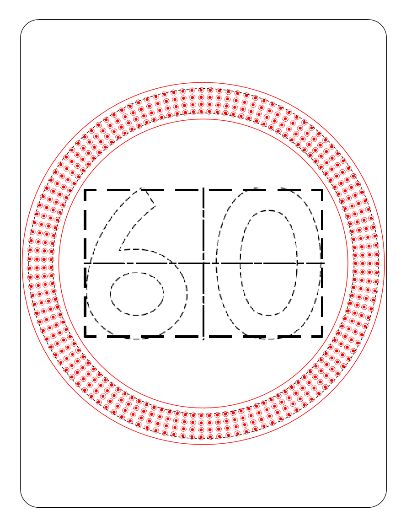
5.4 DISPLAY – MATRIX
5.4.1 Where a matrix display is employed for the numerals the display shall typically consist of an
arrangement as shown in Figure 5.2 below.
Figure 5.2 - Example matrix layout (R4-1B)
5.4.2 Where a matrix display is employed for the numerals the display shall be unable to display
numerals which are not specified in the tender, through exclusion of those frames.
5.4.3 For a matrix display, the pixel pitch shall be equal in the vertical and horizontal direction.
5.4.4 The minimum number of pixels in the vertical direction for a speed numeral shall be 20 as
specified in Clause 2.1.2.3 of AS 5156.
5.4.5 Where the pixel spacing would be greater than 1.5 times the diameter of the pixel, the display
resolution or pixel diameter shall be increased to ensure suitable spacing.
5.5 DISPLAY – ANNULUS
5.5.1 The number of pixel rings used for the annulus shall be as specified in Table 5.2 below.
Sign Number Number Inner Outer Annulus Equivalent
Size of pixel of inner annulus annulus thickness static annulus
rings2 rings to diameter diameter mm thickness
flash mm mm mm
(AS 1743)
A 2 1 ~375 ~425 25 ± 2 45
B 4 3 ~495 ~575 40 ± 3 60
C 5 4 ~730 ~870 70 ± 5 90
Table 5.2 - Annulus size requirements
5.5.2 The total thickness of the annulus (i.e. inside pixel ring to outside pixel ring) will typically be
slightly less than the requirement of AS 1743 due to flaring of the LED’s as shown in Figure
5.3 below.
2
Pixel rings are the number of evenly spaced rings of LEDs which constitute the annulus
Electronic Speed Limit Signs Page 21 of 36TCS 037 - 2019 Rev A
A
B
Figure 5.3 - Example annulus pixel ring spacing
Notes:
A: Equivalent width of annulus for a static sign in accordance with AS 1743 (indicative only).
B: Actual illuminated annulus width using LED pixels (indicative only).
Page 22 of 36 Electronic Speed Limit SignsRev A TCS 037 - 2019
SECTION 6 ELECTRICAL REQUIREMENTS
6.1 GENERAL
6.1.1 All signs shall be designed to operate from a 12Vdc power supply.
6.1.2 Signs shall include an IP65 rated connector to enable the external power supply to be easily
connected and disconnected from the sign.
6.1.3 The LED display modules, displays and associated driver units, monitoring and dimming networks
and the control and communications equipment shall operate at extra low voltage (ELV).
6.1.4 Internal cables shall be laid out and secured to ensure typical maintenance activities, such as
the opening and closing of the door, will not crease or damage cables or components within the
sign.
6.1.5 All equipment shall be internally protected against damage resulting from:
a) lightning strikes at or near the sign
b) electrical transients on power cabling
c) electrical transients on communications wiring
d) radio frequency interference
e) static electrical discharge
6.2 SOLAR POWER
6.2.1 Where specified in individual tender documents, the sign shall be designed for solar operation.
6.2.2 The solar power system shall be designed, constructed and installed in accordance with AS
4509.2, AS 4086.1 and AS 4086.2 as specified in Clause 4.4 of AS 5156.
6.2.3 Where solar power is specified, the contractor shall design a suitable standalone solar power
system, which shall be designed by an accredited or suitably qualified designer.
6.2.4 When designing the standalone solar power system consideration must be given to the power
consumption, the hours of operation, the surrounding environment and the average amount of
sunlight available.
6.2.5 The solar panel shall be installed in a position that minimises the possibility of vandalism and
theft.
6.2.6 The support post shall be suitable for carrying the load associated with the sign, including
battery, and solar panel.
6.2.7 The proposed support post shall be proof engineered by a VicRoads approved consultant.
6.2.8 The solar panel shall be designed for ease of cleaning and equipped with deterrents to bird
roosting.
Electronic Speed Limit Signs Page 23 of 36TCS 037 - 2019 Rev A
6.3 MAINS POWER
6.3.1 The mains supply voltage shall be deemed to be 230Vac +10%, -6% in accordance with AS
60038, Section 2. The system and or sub-elements of the system shall be capable of operating
satisfactorily from the same within ±15%.
6.3.2 For mains power operation, an external 230Vac/12Vdc power supply shall be used to provide
the sign with the required 12Vdc power.
6.3.3 The external power supply to the sign shall incorporate an easily accessible circuit breaker (D-
Curve), as a means to isolate power.
6.3.4 The external power supply and associated electrical installation shall comply with all applicable
requirements of AS/NZS 3000 and AS/NZS 3100.
6.3.5 The sign shall be securely bonded for earthing to the mounting pedestal.
6.3.6 All external joints used for bonding purposes shall be protected from the environment (by
painting or similar method).
6.3.7 All cables and wires shall be insulated with a material with a degree of protection not inferior
to V-90 grade PVC and shall be suitably labelled.
6.3.8 Inrush current at switch on shall be not more than 20% of normal peak operational current.
6.3.9 The supplier shall submit the following details of the power load of each individual sign:
a) Normal peak operation;
b) Dimmed operation;
c) In rush current at switch on.
6.4 BATTERY BACKUP
6.4.1 The sign shall include a battery backup as specified in Clause 4.2.3 of AS 5156 and detailed
below.
6.4.2 Unless otherwise specified in tender documents, the battery system shall be capable of
maintaining normal operation for a minimum period of 48 hours.
6.4.3 In the case of school speed zone signs, the battery system shall be capable of maintaining
normal operation for a minimum period of 1 week, operating for 3 hours per day.
6.4.4 Suitable deep discharge, gel or AGM type batteries shall be used in the backup system.
6.4.5 The service life of the battery shall be not less than three (3) years.
6.4.6 In general, batteries shall comply with AS 4086.1. Additionally, lithium batteries shall comply
with AS IEC 62619.
6.4.7 The installation of batteries shall comply with AS 4086.2.
Page 24 of 36 Electronic Speed Limit SignsRev A TCS 037 - 2019
6.5 ELECTROMAGNETIC COMPLIANCE (EMC)
6.5.1 All signs covered by this specification shall comply with:
• AS/NZS 61000.6.1 for immunity; and
• AS/NZS 61000.6.3 for emissions.
6.5.2 Signs shall also comply with the relevant requirements of the Australian Communications and
Media Authority (ACMA) and shall be labelled with a RCM label as shown in Figure 6.1
Figure 6.1 - RCM Compliance Label
Electronic Speed Limit Signs Page 25 of 36TCS 037 - 2019 Rev A
SECTION 7 MARKINGS AND DOCUMENTATION
7.1 MARKINGS
7.1.1 In addition to the markings and labels identified in AS 5156 Section 4.7, each individual sign
shall be legibly and durably marked on the rear or interior surfaces with:
a) the VicRoads Sign ID
7.1.2 In addition to the markings and labels identified in AS 5156 Section 4.7, each individual module
within the sign shall be legibly and durably marked with:
a) the name, trade name or trademark of the manufacturer;
b) the equipment code or model number;
c) date of manufacture;
d) batch code, serial number, or other marking to provide traceability under the
manufacturer’s quality management system;
e) the type approval number of the relevant Certificate of Suitability (if applicable);
f) RCM certification (as applicable);
g) the rated supply voltage, power and/or current;
7.2 DOCUMENTATION
7.2.1 The manufacturer shall provide the following documentation:
a) Technical and operation manual
b) Field manual
c) Fault finding and diagnostic guide
d) Recommended maintenance requirements
e) List of all recommended spare components to enable fault and maintenance repairs
Page 26 of 36 Electronic Speed Limit SignsRev A TCS 037 - 2019
APPENDIX A NETWORK MANAGEMENT SYSTEM
(Normative)
A1 GENERAL
A1.1 The ESLS Network Management System (NMS) is a monitoring/management system used to
monitor ESLS devices connected to the VicRoads communication network. See Figure B.1
below.
A1.2 A large number of ESLS at school speed zones and strip shopping centres currently use the
ESLS Network Management System (NMS).
Figure B.1 – NMS communication/control schematic
A2 PROTOCOLS
A2.1 Copies of the NMS compatible sign protocol specifications are available upon request from the
Smart Journey Systems group.
Electronic Speed Limit Signs Page 27 of 36TCS 037 - 2019 Rev A
APPENDIX B NETWORK MONITORING AND
CONTROL SYSTEM
(Informative)
B1 GENERAL
B1.1 VicRoads proposes to develop and/or implement a new ESLS Network Monitoring and Control
System (NMCS) in the future.
B1.2 The proposed system is expected to include, as a minimum, the following capability.
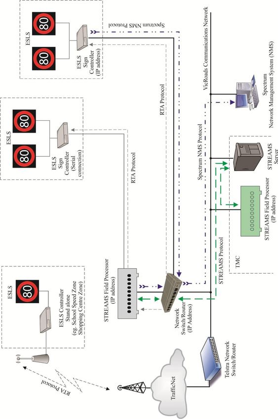
B1.3 The new NMCS will be a monitoring/management system used to monitor ESLS devices
connected to the VicRoads communication network. See Figure A.1 below.
B1.4 In future ESLS at school speed zones and strip shopping centres shall use the Network
Monitoring and Control System (NMCS).
Figure A.1 – Example of possible Network Monitoring and Control System
B2 PROTOCOLS
B2.1 This has been included for possible future use.
Page 28 of 36 Electronic Speed Limit SignsRev A TCS 037 - 2019
APPENDIX C VICROADS ITS PLATFORM
(Informative)
C1 GENERAL
C1.1 VicRoads ITS platform currently uses the STREAMS system.
C1.2 STREAMS is owned and maintained by Transmax Pty Ltd, a Queensland based company
which is part of Queensland Main Roads.
C1.3 STREAMS is an integrated control system which is being used by VicRoads to operate its ITS
Freeway Management Devices on Melbourne’s freeway network.
C1.4 All ITS field devices must be compatible with STREAMS.
C1.5 Typical ITS field devices connected to and operated by STREAMS include:
• Variable Message Signs (VMS)
• Freeway Data Stations (FDS)
• Ramp metering/control signs (RC)
• Lane Control Signs (LCS)
• Lane Use Signs (LUS)
• Travel Time Signs (TTS)
C1.6 The above devices are typically connected to STREAMS via a Field Processor (FP).
C2 FIELD PROCESSOR
C2.1 The FP is used to interface internet protocol (IP) and serially connected field devices to
STREAMS.
C2.2 Communications between the FP and the ITS Field Device is typically RMS protocol.
C2.3 The FP is typically installed within an ITS Field Cabinet.
C2.4 The ITS Field Cabinet is typically located adjacent to the freeway.
C2.5 In some situations, the FP may be located in VicRoads building at Kew.
C2.6 A typical STREAMS connection schematic is shown in Figure C.1.
C3 COMPLIANCE WITH STREAMS
C3.1 Where requested, ESLS must be fully compliant and compatible with STREAMS.
C3.2 To ensure compliance with STREAMS, the supplier shall obtain a compliance certificate from
Transmax Pty Ltd for operation on VicRoads system.
C3.3 A copy of Transmax Pty Ltd certification shall be provided to VicRoads.
Electronic Speed Limit Signs Page 29 of 36TCS 037 - 2019 Rev A
C4 SPECTRUM NETWORK MANAGEMENT SYSTEM
C4.1 The Spectrum Network Management System (Spectrum NMS) is a communications
monitoring/management system used to monitor/manage IP addressable devices connected to
the VicRoads communication network.
C4.2 Spectrum NMS can be used to monitor/manage any device that has an IP address without any
modification required by the device.
Figure C.1 - STREAMS communications/control schematic
Page 30 of 36 Electronic Speed Limit SignsRev A TCS 037 - 2019
APPENDIX D FAULT NOTIFICATIONS AND
LOGGING
(Normative)
D1 MINIMUM REQUIRED FAULT NOTIFICATIONS
D1.1 Each ESLS shall provide to the control system, as a minimum, the alarm notifications detailed
in Table D.1.
Alarm Description Classification Required System
Response
GPS Invalid The sign has failed to obtain a valid Critical Display Alarm & raise a
data string from the GPS network to fault.
synchronise its internal time clock for
the past 24 hours.
GPS Fail The sign has failed to obtain any Critical Display Alarm & raise a
data from the GPS network for the fault.
past 24 hours.
Processor Watchdog The sign processor has flagged a Critical Display Alarm & raise a
watchdog alarm. fault.
Processor or The sign processor or system has Critical Display Alarm & raise a
System Failure failed. fault.
Communications Failure The sign has stopped Critical Display Alarm & raise a
communicating with the fault.
management system.
Power Supply Failure The sign has lost internal power. Critical Display Alarm & raise a
fault.
Mains Failure The external power source to the Critical Display Alarm & raise a
sign has failed. fault.
Solar Panel Failure The solar panel has stopped Critical Display Alarm & raise a
operating. fault.
Solar panel tamper The solar panel has been moved. Critical Display Alarm & raise a
fault.
Battery Level Warning 1 The battery has 24 hours of charge Critical Display Alarm & raise a
left. fault.
Battery Level Warning 2 The battery has less than 6 hours Critical Display Alarm & raise a
charge left. fault.
Battery Failure The battery has failed. Critical Display Alarm & raise a
fault.
Battery Overcharge The battery is overcharged or Critical Display Alarm & raise a
exceeded maximum operating fault.
temperature.
Excessive The internal temperature of the sign Critical Display Alarm & raise a
Internal has exceeded the maximum safe level fault.
Temperature for the internal components.
Display shut 20% of the LED’s in a numeral Critical Display Alarm & raise a
down - have failed and the sign has fault.
Numerals shutdown.
Display shut 20% of the LED’s in the annulus Critical Display Alarm & raise a
down - have failed and the sign has fault.
Numerals shutdown.
Facility Switch Facility switch has been set to a Critical Display Alarm & raise a
– Not in AUTO set speed. fault.
position
Electronic Speed Limit Signs Page 31 of 36TCS 037 - 2019 Rev A
Facility Switch Facility switch has been turned to Critical Display Alarm & raise a
– OFF the ‘OFF’ position. fault.
Door The sign door is open Critical Display Alarm & raise a
fault.
Tilt The sign is no longer vertical Critical Display Alarm & raise a
fault.
Surge Surge Protection device is low Minor Display Alarm & raise a
Protection fault.
Table D.1 - Minimum required fault notifications
D2 MINIMUM LOGGING REQUIREMENTS
D2.1 Each ESLS shall provide store, as a minimum, the log entries detailed in Table D.2 below.
Entry Description Classification
Battery Overcharge The battery is overcharged or exceeded Battery fault/status
maximum operating temperature.
Battery low status level 3 Battery low status level 3 - critical Battery status
(shutdown).
Battery low status level 2 Battery low status level 2 - 6 hours of charge left. Battery status
Battery low status level 1 Battery low status level 1 - 24 hours of charge left. Battery status
Mains Failure The external power source to the sign has failed. Mains fault/status
Surge Protection Surge Protection device is low Sign fault/status
Solar Panel Failure The sign has lost internal power. Sign fault/status
Solar panel tamper The solar panel has been moved. Sign fault/status
10% LED failure - 10% of the LED’s in annulus have failed. Sign display
Annulus fault/status
20% LED failure - 20% of the LED’s in annulus have failed. Sign display
Annulus fault/status
LED failure – Annulus Annulus has failed. Sign display
Failed fault/status
20% LED failure - 20% of the LED’s in any numeral have failed Sign display
Digits fault/status
LED failure – Annulus Digits have failed. Sign display
Digits fault/status
Dimming mode Automatic or manual dimming mode Sign status
Luminance level Current luminance level Sign status
Luminance controller Sign luminance controller failure Sign fault/status
failure
Tilt Sign tilt error Sign fault/status
Page 32 of 36 Electronic Speed Limit SignsRev A TCS 037 - 2019
Sign time Current sign time in seconds Sign status
Firmware version Current sign firmware of the sign Sign status
Sign manufacturer Sign manufacturer Sign status
Sign model Sign model Sign status
Critical error The sign is disabled due to a critical error and Sign status/error
hasn’t been overridden or cleared to run
automatically by an operator or technician
Sign up time The time/duration of continuous operation of the Sign status
sign
Sign rings Number of rings of in the annulus to flash Sign status
Control mode Manual or automatic sign operation mode Sign status
Door Sign open door alarm Sign status/alarm
GPS status Current status of GPS Sign status
Site ID Site ID of the sign Sign status
Sign ID ID allocated to the sign Sign status
Temperature Current temperature of the sign Sign status
Phone number Phone number of the sign’s sim card Sign status
Number of signs in Number of signs in Group Sign status
Group
Solar current Solar current measurement Sign status
Battery status Current battery measurement Sign status
Voltage level Current battery voltage measurement Sign status
Internal Internal communications failure Sign status/error
communication error
Display time-out Sign display time-out Sign status/error
Master/Slave comms Master/Slave comms failure Sign status/error
failure
Watchdog The sign processor has flagged a watchdog alarm. Sign status/error
Table D.2 - Minimum logging requirements
Electronic Speed Limit Signs Page 33 of 36TCS 037 - 2019 Rev A
APPENDIX E GUIDELINES FOR PURCHASING AND
INSTALLATION
(Informative)
E1 DETAILS TO BE INCLUDED WHEN TENDERING
E1.1 Installation requirements will be site specific and detailed in individual tender documents.
E1.2 The following details should be considered when preparing tender documents:
a) The size of the proposed signs, i.e. whether A, B or C size;
b) Whether single speed, dual speed or multiple speed;
c) Whether the proposed signs are mains or solar powered;
d) Requirements for battery backup;
e) Whether the display is discrete or a matrix;
f) The numbers of signs and speed values to be provided;
g) The proposed activation mode;
h) The method of monitoring and control system (NMCS, NMS, STREAMS, SCATS,
SRAS) the signs are to be operated on,
i) The mounting arrangements for the signs;
Page 34 of 36 Electronic Speed Limit SignsRev A TCS 037 - 2019
APPENDIX F REQUIREMENTS FOR TYPE
APPROVAL
(Normative)
F1 GENERAL
F1.1 Electronic Speed Limit signs for use on VicRoads projects are required to hold current
VicRoads Type Approval.
F1.2 The Product Compliance evaluation process shall be carried out in accordance with VicRoads
Guideline TCG 016.
F1.3 To enable assessment for the purpose of granting Type Approval, the manufacturer/supplier is
to submit a formal request for Type Approval, for each sign type submitted, accompanied by
the following:
• A complete working sample of the sign.
• An outline drawing showing the general presentation and overall dimensions of the
complete sign.
• Documentation to demonstrate that the sign has been manufactured and supplied under an
approved quality assurance system.
• Documentation to demonstrate that the sign conforms to the requirements of VicRoads
Specification. This may be by means of submitting test results from approved and
appropriately qualified independent testing organisations, or providing the manufacturer’s
assurance that the product complies with each paragraph of the specification, as
appropriate.
F2 REQUIRED NATA ACCREDITED TESTING
F2.1 Notwithstanding F1 above, the manufacturer/supplier shall submit test results from a NATA
accredited testing organisation to demonstrate compliance with the following:
Requirements
Evidence
(in accordance with AS 5156)
Temperature and humidity Test Report
Enclosure protection Test Report
EMC Compliance Test Report
Photometric Test Report
Colorimetric Test Report
F3 COMPATIBILITY WITH NMCS
F3.1 Where applicable, the supplier shall provide evidence of compatibility with the NMCS.
F4 COMPATIBILITY WITH NMS
F4.1 ESLS intended to be connected to the NMS must be fully compliant and compatible.
Electronic Speed Limit Signs Page 35 of 36TCS 037 - 2019 Rev A
F4.2 To ensure compliance the supplier shall obtain a compliance certificate prior to operation on
the NMS.
F4.3 A copy of this certification shall be provided to VicRoads.
F5 COMPATIBILITY WITH STREAMS
F5.1 Where applicable, the supplier shall provide evidence of compatibility with STREAMS.
F6 OTHER REQUIRED INFORMATION
F6.1 Confirmation that the manufacturer is on the VicRoads Register for the Pre-qualification for
Supply of On-Road Electronic Devices.
F6.2 Copy of LED manufacturer’s specification for each LED type used.
F7 ASSESSMENT PROCEDURE
F7.1 The assessment procedure for an ESLS may include, but not limited to, the following:
a) Assessment of construction, workmanship and critical dimensions;
b) Preliminary assessment of the sign under continuous burning at the VicRoads Test Rack
for a period of not less than three months; and
c) Evaluation of the submitted data against the requirements of the specification.
F7.2 Where some of these procedures have been completed prior to formal submission, the results
will be considered in the evaluation, provided there is no relevant change in the design of the
sign.
F7.3 The supplier is to state whether tests carried out prior to formal submission were carried out on
an identical sample of the sign.
F7.4 VicRoads may require a trial installation of the sign to be undertaken.
F8 TYPE APPROVAL
F8.1 The decision to grant a Certificate of Type Approval is at the sole discretion of VicRoads.
F8.2 VicRoads may require additional information or testing to be carried out as part of its evaluation
of the product.
F8.3 If the product is approved, a Certificate of Type Approval will be provided to the supplier.
Until such time as this Certificate is issued, the product is not to be used for VicRoads works.
Page 36 of 36 Electronic Speed Limit SignsYou can also read