TCS 037:2021 Electronic Speed Limit Signs - Supply and Installation Version: 2021 Revision: A - VicRoads
←
→
Page content transcription
If your browser does not render page correctly, please read the page content below
TCS 037:2021

Specification

Electronic Speed Limit Signs
Supply and Installation

Version: 2021
Revision: A
Department of Transport (Roads)

      TCS 037:2021

                                                            Foreword

                                                            This specification has been developed by Department of
                                                            Transport (DoT). It is one of a number of technical
                                                            specifications, and associated standard drawings, which
                                                            set out the requirements for roadside ITS devices, traffic
                                                            signal equipment and other electrical equipment and
                                                            associated devices and control systems.

                                                            This specification is intended for use in all relevant
                                                            works undertaken by or on behalf of DoT (Roads).

                                                            Dot (Roads) Standard Drawings, Specifications and
                                                            Guidelines are available for downloading from the
                                                            VicRoads website:
                                                            https://www.vicroads.vic.gov.au/business-and-
                                                            industry/technical-publications/electrical-and-intelligent-
                                                            transport-systems

      COPYRIGHT                                             Specification updates. DoT (Roads) specifications and
                                                            associated standard drawings are subject to periodic
      © Department of Transport. All rights reserved.       review. To keep the specifications up to date,
                                                            amendments or new editions are issued as necessary. It
      This document remains the property of DoT             is therefore important for users of DoT (Roads)
      (Roads). No part of this document may be              specifications to ensure that they have the latest version
      reproduced or copied in any form or by any means,     and associated amendments.
      electronic or mechanical, including photocopying,
      without the written permission of DoT (Roads)

                                                            Intelligent Transport Systems
                                                            60 Denmark Street Kew 3101

                                                            ITS_Improvements_and_standards@roads.vic.gov.au

                                                       TCS 037:2021
 Page 2 of 34                                   Electronic Speed Limit Signs                                         Rev. A
Department of Transport (Roads)

                                              Revision History

Version         Revision            Date       Author                          Description

   2001            1                April         ITS                        New specification

   2001         2,3 & 4                           ITS                          Not released

   2001            5              September       ITS                          Amendment

   2003            6                June          ITS                          Amendment

   2004            7               January        ITS                          Amendment

                                                             Incorporate AS 5156, AS 4509.2, AS 4086.1 &
   2014            A              December        SJS        AS 4086.2
                                                             Incorporate Tyco ESLS Management System
                                                             Amendment to existing specification
                                                             Incorporate Network Monitoring and Control
   2019            A               January        SJS        System
                                                             Incorporate Side Road Activated Speed (SRAS)
                                                             system
                                                             Updated to reflect changes and content order of
                                                             AS 5156:2020
   2021            A                May           ITS        Confirmed NMS as host control system
                                                             Updated to DoT template
                                                             Expanded installation section

                                                     TCS 037:2021
 Page 3 of 34                                 Electronic Speed Limit Signs                            Rev. A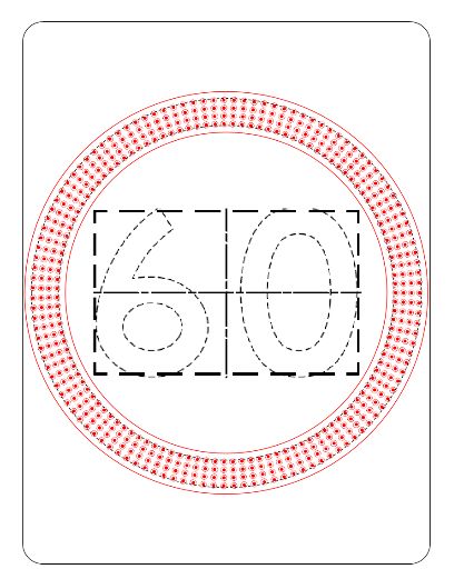
Department of Transport (Roads)

                                                        Contents

SECTION 1             SCOPE AND GENERAL ........................................................................... 6
  1.1       SCOPE .............................................................................................................................. 6
  1.2       GENERAL ........................................................................................................................ 6
  1.3       INTELLECTUAL PROPERTY ......................................................................................... 6
  1.4       ACRONYMS..................................................................................................................... 7

SECTION 2             RELATED SPECIFICATIONS AND DRAWINGS ................................. 8
  2.1       AUSTRALIAN STANDARDS .......................................................................................... 8
  2.2       DOT (ROADS) SPECIFICATIONS AND DRAWINGS .................................................... 8
  2.3       EXCEPTIONS AND CLARIFICATIONS TO AS 5156:2020 ............................................ 9

SECTION 3             MECHANICAL REQUIREMENTS ....................................................... 10
  3.1       GENERAL ...................................................................................................................... 10
  3.2       SIGN MOUNTING FACILITIES .................................................................................... 10
  3.3       ROADSIDE CABINET ................................................................................................... 11
  3.4       FACILITY SWITCH ....................................................................................................... 11

SECTION 4              ELECTRICAL REQUIREMENTS ........................................................ 13
  4.1    GENERAL ...................................................................................................................... 13
  4.2    OPERATING VOLTAGE................................................................................................ 13
  4.3    BATTERY BACKUP ...................................................................................................... 14
    4.3.1   General..................................................................................................................... 14
    4.3.2   Battery Enclosure ..................................................................................................... 14
  4.4    SOLAR POWER ............................................................................................................. 14
  4.5    ELECTROMAGNETIC COMPLIANCE (EMC) ............................................................. 15

SECTION 5             DISPLAY AND OPTICAL ...................................................................... 16
  5.1    GENERAL ...................................................................................................................... 16
  5.2    DISPLAY CHARACTERISTICS .................................................................................... 16
    5.2.1    General..................................................................................................................... 16
    5.2.2    Matrix Numerals ...................................................................................................... 17
    5.2.3    Discrete Numerals .................................................................................................... 17
  5.3    ANNULUS DISPLAY ..................................................................................................... 18
  5.4    SYNCHRONISATION OF NUMERIC DISPLAY CHANGES........................................ 18
  5.5    CONSPICUITY DEVICES .............................................................................................. 18
  5.6    FLASHING ANNULUS .................................................................................................. 19

SECTION 6             OPERATION AND CONTROL .............................................................. 20
  6.1       GENERAL ...................................................................................................................... 20
  6.2       ESLS NETWORK MANAGEMENT SYSTEM ............................................................... 20

                                                                TCS 037:2021
 Page 4 of 34                                            Electronic Speed Limit Signs                                                   Rev. A
Department of Transport (Roads)
6.3 SIGN ACTIVATION ....................................................................................................... 21
6.4 SYNCHONISATION OF SIGNS REAL-TIME CLOCK ................................................. 21
6.5 LOCAL CONTROL......................................................................................................... 21
6.6 REMOTE CONTROL...................................................................................................... 21
6.7 COMMUNICATIONS EQUIPMENT .............................................................................. 22
6.8 MONITORING ................................................................................................................ 22
6.9 LOGGING ....................................................................................................................... 22
6.10 FALL-BACK OPERATION ............................................................................................ 22
6.11 PROGRAMMING AND MAINTENANCE ..................................................................... 23
6.11.1 General..................................................................................................................... 23
6.11.2 Maintenance Requirements ....................................................................................... 23
6.11.3 Replacement Components ........................................................................................ 23
6.12 SIDE ROAD ACTIVATED SPEED................................................................................. 23
SECTION 7 MARKINGS AND DOCUMENTATION............................................... 24
7.1 MARKINGS .................................................................................................................... 24
7.2 DOCUMENTATION ....................................................................................................... 24
SECTION 8 INSTALLATION AND COMMISSIONING ......................................... 25
8.1 GENERAL ...................................................................................................................... 25
8.2 PRE-INSTALLATION TESTING ................................................................................... 25
8.3 INSTALLATION............................................................................................................. 25
8.4 SUPPORT POSTS ........................................................................................................... 26
8.5 MAINS POWER SUPPLY .............................................................................................. 26
8.6 COMMUNICATIONS ..................................................................................................... 26
8.7 COMMISSIONNG .......................................................................................................... 26
APPENDIX A NETWORK MANAGEMENT SYSTEM ............................................... 27
APPENDIX B FAULT NOTIFICATIONS AND LOGGING......................................... 29
APPENDIX C GUIDELINES FOR PURCHASING AND INSTALLATION ............... 32
APPENDIX D REQUIREMENTS FOR TYPE APPROVAL......................................... 33
TCS 037:2021
Page 5 of 34 Electronic Speed Limit Signs Rev. ADepartment of Transport (Roads)
SECTION 1 SCOPE AND GENERAL
1.1 SCOPE
1.1.1 This specification covers the design, manufacture, installation, and operation of Electronic
Speed Limit Signs (ESLS) intended for use as school speed zone, strip shopping centre zone
and Side Road Activated Speed (SRAS) treatments.
1.1.2 This specification is not intended to cover the requirements of ESLS used as part of Lane Use
Management Systems (LUMS). The requirements for Lane Use Signs (LUS) are outside the
scope of this specification.
1.1.3 This specification is based on the use of LED’s as the light-emitting elements. Other
technologies that meet the performance requirements of this specification may be considered.
1.2 GENERAL
1.2.1 ESLS are used to display a legally enforceable speed limit to be adopted at different times
though-out the day. Any reference to “sign” within this document shall be taken to mean
“Electronic Speed Limit Sign”.
1.2.2 Only DoT (Roads) type approved ESLS shall be used for any DoT (Roads) project.
1.2.3 Individual tender documents shall detail the types of signs required for a specific project.
1.2.4 The sign display shall be made up of point light sources, arranged in accordance with this
specification to comprise a clear and enforceable speed limit sign.
1.2.5 This specification should be read in conjunction with AS 5156.
1.2.6 Signs are to be designed and constructed to conform to AS 5156 except where modified to
meet the requirements stated in this document. Details of the exceptions and clarifications
from AS 5156 are given in Section 2.4.
1.2.7 All ESLS shall be DoT (Roads) Type Approved as detailed in APPENDIX C.
1.3 INTELLECTUAL PROPERTY
1.3.1 In relation to all Intellectual Property used in/or to operate the system, the manufacturer shall
grant to DoT non-exclusive licence to use or provide to DoT authorised contractors any and
all software, firmware or programs required to operate and maintain the ESLS and
components that without the licence, could be in breach of the licensors Intellectual Property.
1.3.2 Intellectual Property shall include, but not be limited to, the following:
• Software required to program and configure individual signs.
• Software required to enable maintenance and fault finding of signs
TCS 037:2021
Page 6 of 34 Electronic Speed Limit Signs Rev. ADepartment of Transport (Roads)
• Schematic diagrams.
• Circuit diagrams.
• Wiring diagrams.
• Listings of replaceable components and sub-components.
• Any and all operational and maintenance documentation.
1.4 ACRONYMS
The acronyms used in this document shall be interpreted as follows:
ACMA Australian Communications and Media Authority
AS Australian Standard
DoT (Roads) Department of Transport (Roads) (formerly VicRoads)
ELV Extra Low Voltage
EMC Electromagnetic Compatibility
ESLS Electronic Speed Limit Sign
GPS Global Positioning System
GNSS Global Navigation Satellite System
IP Ingress Protection (degree of protection)
ITS Intelligent Transport System
LED Light Emitting Diode
NMCS Network Management and Control System
NMS Network Management System
NZS New Zealand Standard
RCD Residual Current Device
RCM Regulatory Compliance Mark
SNMP Simple Network Management Protocol
SRAS Side Road Activated Speed
TCP/IP Transmission Control Protocol/Internet Protocol
UTC Coordinated Universal Time
TCS 037:2021
Page 7 of 34 Electronic Speed Limit Signs Rev. ADepartment of Transport (Roads)
SECTION 2 RELATED SPECIFICATIONS AND
DRAWINGS
2.1 AUSTRALIAN STANDARDS
2.1.1 Subject to the following clauses, the fabrication and supply of all components for ESLS shall
fully comply with the most recent issue of the Australian Standards listed below, together
with any amendments to these standards.
2.1.2 The following related Australian Standards are referenced:
AS 1742.2 Manual of Uniform Traffic Control Devices, Part 2, Traffic
Control Devices for General use
AS 1743 Road signs – Specifications
AS/NZS 3000 Wiring Rules
AS 4086.2 Secondary batteries for use with stand-alone power systems -
Installation and maintenance
AS/NZS 4509.1:2019 Stand-alone power systems – Safety and installation
(reconfirmed 2017)
AS 5156:2020 Electronic speed limit signs
AS 60529 Degrees of protection provided by enclosures (IP code).
AS IEC 62619 Secondary cells and batteries containing alkaline or other non-acid
electrolytes — Safety requirements for secondary lithium cells and
batteries, for use in industrial applications
AS/NZS 61000.6.1 Electromagnetic compatibility (EMC), General Standards –
Immunity for residential, commercial and light industrial
environments
AS/NZS 61000.6.3 Electromagnetic compatibility (EMC), General Standards –
Emission standard for residential, commercial and light industrial
environments
2.2 DOT (ROADS) SPECIFICATIONS AND DRAWINGS
2.2.1 The fabrication and supply of all components shall conform to the relevant DoT (Roads)
specifications, and related specifications and standards, as indicated throughout this
document.
2.2.2 All installation works shall conform to the relevant DoT (Roads) specifications and related
specifications and standards.
2.2.3 The following DoT (Roads) Contract Standard Section Specifications are referenced:
TCS 037:2021
Page 8 of 34 Electronic Speed Limit Signs Rev. ADepartment of Transport (Roads)
Standard Section 730 Traffic signal installation
Standard Section 732 ITS Devices installation
Standard Section 736 ITS Device testing and integration
2.2.4 The following DoT (Roads) specifications and guidelines are defined:
TCG 016 Product Compliance Process for ITS and Electrical Products
TCG 018 Register of ITS Approved Products
TCN 011 Modems for ITS Devices
TCS 060 VicRoads Extensions to RTA Protocol for Roadside Devices
TCS 071 Side Road Activated Speed (SRAS)
2.3 EXCEPTIONS AND CLARIFICATIONS TO AS 5156:2020
Changes or clarifications to AS 5156 are summarised in Table 2.1 below.
AS 5156
Description TCS 037 Exception / Clarification
Clause
3.1 (a) Sign enclosure – viewing window Refer to clauses 4.1.1 and 4.1.2.
3.1 (b) Sign enclosure –doors Refer to Clause 4.1.4
3.2 Sign Mounting facilities Refer to Clause 4.2
3.3 Roadside cabinet Refer to Clause 4.3
3.4 Facility switch Refer to Clause 4.4
4.2.1 Operating voltage - General Refer to Clause 5.2
4.2.2 Battery backup Refer to Clause 5.3
4.3 Solar power Refer to Clause 5.4
4.4 Communications equipment Refer to Clause 6.7
4.5 Real-time clock Refer to Clause 6.4
4.6 EMC Refer to Clause 4.5
5.1.1.1 Display characteristics Refer to Clause 5.2
5.1.2.6 Annulus display Refer to Clause 5.3
5.7.7 Conspicuity devices Refer to Clause 5.5
5.2.5 Flashing annulus Refer to Clause 5.6
6 Operation and control Refer to Section 6
TABLE 2.1 – Changes and clarifications to AS 5156
TCS 037:2021
Page 9 of 34 Electronic Speed Limit Signs Rev. ADepartment of Transport (Roads)
SECTION 3 MECHANICAL REQUIREMENTS
3.1 GENERAL
3.1.1 Signs shall conform to the requirements of Section 3 of AS 5156.
3.1.2 The rear of the sign enclosure shall be matt grey.
3.1.3 Where a viewing window is provided, it shall comply with the requirements of AS5156,
Clause 3.1(a).
3.1.4 Where a viewing window is not provided, it shall comply with the requirements of AS5156,
Clause 3.1(b).
3.1.5 Signs shall include a front opening door.
3.1.6 The sign shall be capable of having the door hinged on either the right or left side to enable
the door to always be swung to the footpath side of the sign. The required hinge side shall be
specified in individual contract documents.
3.1.7 The door shall be fitted with a tamper switch to sense when it is open or incorrectly secured.
3.1.8 The sign enclosure shall include an internal battery enclosure as specified in Clause 4.3.2.
3.1.9 All metal seams shall be continuous welded. Spot welding shall not be used.
3.1.10 The height and width dimensions of the sign face shall not exceed 100 mm difference
compared with the equivalent static sign (R4-1).
3.1.11 The height and width of the sign enclosure shall be designed so that no part of the annulus is
closer than 40mm to the outside edge of the enclosure.
3.1.12 Each door shall be securely closed using two locks. The locks shall be “Southco”, key
lockable, Link Lock™, Rotary Action Latches (Code 801). All locks shall be keyed alike and
shall ensure that the door is securely fastened.
3.1.13 Alternative rotary action latches may be considered, provided they use the same key as
detailed in 3.1.12 above
3.1.14 A shroud or visor is not required. Signs shall be designed in such a way that a shroud or visor
is not required to achieve the requirements of Section 6 of this specification.
3.2 SIGN MOUNTING FACILITIES
3.2.1 Unless otherwise specified in individual contract documents, signs shall be designed to be
mounted from the rear of the enclosure.
3.2.2 Unless otherwise specified, each sign shall be designed to be mounted directly onto a 2A
traffic signal pedestal (typically for A size signs) or a 2B pedestal (typically for B and C size
signs).
TCS 037:2021
Page 10 of 34 Electronic Speed Limit Signs Rev. ADepartment of Transport (Roads)
3.2.3 Attachment to the pedestal may be facilitated using standard traffic signal mounting straps
that comply with AS 2339, Section 6.1. Specifically, the lantern straps shall conform to ‘size
designation 3’ of Figure 6.3 and be 300mm in length with 260mm ‘hole-centres’.
3.2.4 Other mounting methods may be considered.
3.2.5 Where specified in individual contract documents, signs may be required to be mounted on a
purpose-built pole designed for the sign enclosure to be secured at the base.
3.2.6 The mounting method shall ensure that the display face of the sign is vertical and has provision
for adjustment of the vertical and horizontal alignment.
3.2.7 2A and 2B pedestals shall be installed in accordance with the relevant requirements of
VicRoads Standard Section 730 Traffic Signal Installation.
3.2.8 For signs mounted on a 2A or 2B pedestal, access for all power supply, control and
communication cabling shall be through the centre of the pedestal and shall enter the sign
housing through appropriately constructed, sealed entry holes.
3.2.9 For base mounted signs, access for all power supply, control and communication cabling shall
be through the centre of the pole and shall enter the sign housing through an appropriately
constructed, sealed entry hole in the base on the sign enclosure.
3.3 ROADSIDE CABINET
3.3.1 For ESLS at school and strip shopping centre speed zones, a roadside cabinet shall not be
used.
3.3.2 All equipment such as the sign controller, modem, batteries, etc shall be housed within the
sign enclosure.
3.3.3 For ESLS as part of a SRAS system, a roadside cabinet shall be used in accordance with TCS
071.
3.4 FACILITY SWITCH
3.4.1 An external facility switch on the sign enclosure shall not be provided.
3.4.2 Each sign shall incorporate an internal facility switch function or manual override function
(manual switch and/or software switch), accessible from the inside of the housing.
3.4.3 The function shall include the following options:
(a) For single speed signs the options detailed in Table 3.1 below.
(b) For dual speed signs the options detailed in Table 3.2 below.
(c) For multiple speed signs the options detailed in Table 3.3 below.
TCS 037:2021
Page 11 of 34 Electronic Speed Limit Signs Rev. ADepartment of Transport (Roads)
Option Function
AUTO Shall allow the sign to operate normally and be controlled via the
management system
OFF Shall switch the sign off and prevent control via the management system
ON Shall switch on the display and prevent control via the management system
Table 3.1 - Single Speed Signs
Option Function
AUTO Shall allow the sign to operate normally and be controlled via the
management system
OFF Shall switch the sign off and prevent control via the management system
SPEED 1 Shall switch on the lowest speed and prevent control via the management
SPEED 2 Shall switch on the second speed and prevent control via the management
Table 3.2 - Dual Speed Signs
Option Function
AUTO Shall allow the sign to operate normally and be manually switched via
the management system
OFF Shall switch the sign off and prevent control via the management system
SPEED 1 Shall switch on the 1st (lowest) speed and prevent control via the management
SPEED 2 Shall switch on the 2nd speed and prevent control via the management system
SPEED (n) Shall switch on the nth speed and prevent control via the management system
Table 3.3 – Multiple speed ESLS
3.4.4 The local manual override shall override all commands received from the management
system. Under no circumstances shall the management system be capable of overriding the
display, unless the sign is in AUTO.
TCS 037:2021
Page 12 of 34 Electronic Speed Limit Signs Rev. ADepartment of Transport (Roads)
SECTION 4 ELECTRICAL REQUIREMENTS
4.1 GENERAL
4.1.1 The mains supply voltage shall be deemed to be 230Vac +10%, -6% in accordance with AS
60038, Section 2. The system and or sub-elements of the system shall be capable of operating
satisfactorily from the same within ±15%.
4.1.2 All LV works shall comply with the requirements of AS/NZS 3000.
4.1.3 Signs shall include an IP65 rated connector to enable the external power supply to be easily
connected and disconnected from the sign.
4.1.4 All cables and wires shall be insulated with a material with a degree of protection not inferior
to V-90 grade PVC and shall be suitably labelled.
4.1.5 Internal cables shall be laid out and secured to ensure typical maintenance activities, such as
the opening and closing of the door, will not crease or damage cables or components within
the sign.
4.1.6 All equipment shall be internally protected against damage resulting from:
a) lightning strikes at or near the sign
b) electrical transients on power cabling
c) electrical transients on communications wiring
d) radio frequency interference
e) static electrical discharge
4.1.7 Inrush current at switch on shall be not more than 20% of normal peak operational current.
4.1.8 The supplier shall submit the following details of the power load of each individual sign:
a) Normal peak operation.
b) Dimmed operation.
c) In rush current at switch on.
4.2 OPERATING VOLTAGE
4.2.1 All signs shall be designed to operate from a nominal 12volt DC power supply.
4.2.2 Where specified in individual contract documents, signs shall be powered from mains power
via a 240Vac/12Vdc power supply mounted on the support post external to the sign enclosure.
4.2.3 The external power supply to the sign shall incorporate an easily accessible circuit breaker
(D-Curve), as a means to isolate power.
4.2.4 The enclosure used for the external, 12volt DC power supply shall be rated at not less than IP
65 and be UV stabilised for outdoor applications.
4.2.5 Under no circumstances, shall LV be present internally in the sign.
4.2.6 Signs powered from solar shall comply with Clause 4.4.
TCS 037:2021
Page 13 of 34 Electronic Speed Limit Signs Rev. ADepartment of Transport (Roads)
4.3 BATTERY BACKUP
4.3.1 General
4.3.1.1 Battery backup shall be provided for each sign.
4.3.1.2 The installation of batteries shall comply with relevant requirements of AS 4086.1.
4.3.1.3 Typically, the capacity of the battery backup shall be capable of maintaining normal operation
for a minimum period of 48 hours.
4.3.1.4 In the case of school speed zone signs, the backup battery system shall be capable of
maintaining normal operation for a minimum period of 1 week, operating for 3 hours per day.
4.3.1.5 The service life of the battery shall be not less than three years.
4.3.2 Battery Enclosure
4.3.2.1 Batteries installed as an integral part of the sign enclosure shall be located within a battery
enclosure as specified in AS 4509.1, Clause 7.2(a).
4.3.2.2 The battery enclosure shall be:
a) Only accessible internally in the sign through the front opening door.
b) Accessible by removing a front access panel.
c) Sealed on the front access panel to prevent any gases from leaking into the sign enclosure.
d) Vented through the exterior of the sign enclosure to prevent the build-up of gas.
e) Be rated at not less than IP45.
4.3.2.3 Venting of the battery enclosure shall not reduce the IP rating of the rest of the sign enclosure.
4.4 SOLAR POWER
4.4.1 Where specified in individual tender documents, the sign shall be designed for solar operation.
4.4.2 The solar power system shall be designed, constructed and installed in accordance with AS
4509.2, AS 4086.1 and AS 4086.2 as specified in Clause 4.3 of AS 5156:2020.
4.4.3 Where solar power is specified, the contractor shall be responsible for the design of a suitable
standalone solar power system. All solar system calculations shall be checked by a suitably
qualified or experienced solar power expert.
4.4.4 When designing the standalone solar power system consideration must be given to the power
consumption, the hours of operation, the surrounding environment and the average amount of
sunlight available.
4.4.5 The solar panel shall be installed in a position that minimises the possibility of vandalism and
theft.
4.4.6 The support post shall be suitable for carrying the load associated with the solar panel, storage
batteries and the sign.
4.4.7 The proposed support post and associated foundation shall be proof engineered by a DoT
(Roads) approved consultant.
TCS 037:2021
Page 14 of 34 Electronic Speed Limit Signs Rev. ADepartment of Transport (Roads)
4.4.8 Standard Type 2 pedestals shall not be used for the of mounting solar panels.
4.4.9 The solar panel shall be designed for ease of cleaning and equipped with deterrents to bird
roosting.
4.5 ELECTROMAGNETIC COMPLIANCE (EMC)
In addition to the requirements of AS 5156, Clause 4.6, signs shall be labelled with a RCM label as
required by ACMA. See Figure 4.1
Figure 4.1 - RCM Compliance Label
TCS 037:2021
Page 15 of 34 Electronic Speed Limit Signs Rev. ADepartment of Transport (Roads)
SECTION 5 DISPLAY AND OPTICAL
5.1 GENERAL
5.1.1 The display shall conform to the relevant requirements of AS 5156.
5.1.2 The speed limit values and sign sizes to be supplied shall be as specified in individual contract
documents.
5.1.3 The display shall be formed from LED pixels to comply with Section 5 of AS 5156 and this
specification.
5.1.4 Where 3mm LED’s are used, greater pixel spacing may be considered.
5.1.5 If 20% or more of the LEDs in any one element of the display fail, the whole display shall be
shut down and the sign deemed to have failed.
5.1.6 Any single numeral shall be considered a single element. The annulus shall be deemed to be
a single element.
5.1.7 When displaying other than the normal speed limit, the red annulus shall be designed so that
all inner rings of the annulus flash on and off. The number of rings of the annulus that flash
shall be in accordance with Clause 5.6 below.
5.1.8 Signs shall incorporate features to provide a completely blank (all pixels inactive) display.
5.1.9 The design of the sign display shall ensure that there is an adequate space between the inner
ring of the annulus and any numeral adjacent to the annulus. This is to prevent ‘bleeding’ of
the LED’s into adjacent LED’s and provide a clear display.
5.2 DISPLAY CHARACTERISTICS
5.2.1 General
5.2.1.1 Further to Clause 5.1.1.1 of AS 5156, the numeral display types shown in Table 5.1 shall be
used.
Number of Speed Displays Approved Sign Display Type
Discrete character
Single speed or
Matrix (where protocol allows)
Discrete character
Dual speed or
Matrix (where protocol allows)
Three or more speed Matrix (only)
Table 5.1 – Approved ESLS versions
TCS 037:2021
Page 16 of 34 Electronic Speed Limit Signs Rev. ADepartment of Transport (Roads)
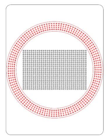
5.2.2 Matrix Numerals
5.2.2.1 Where a matrix display is employed for the numerals the display shall be unable to display
numerals which are not specified in the tender, through exclusion of those frames.
5.2.2.2 The pixel pitch shall be equal in the vertical and horizontal direction.
5.2.2.3 Figure 5.1 shows a typical layout for a matrix display.
Figure 5.1 - Example matrix layout (R4-1B)
5.2.3 Discrete Numerals
5.2.3.1 Numerals shall be configured in accordance with Table 5.2 below, for the respective R4-1
sign sizes specified in AS 1743:
Sign Size Number of Stroke
pixel rows width
A 2 ~25mm
B 2 ~35mm
C 2 ~45mm
Table 5.2 - Discrete numeral requirements
5.2.3.2 The total size of the stroke width (i.e. outside to outside of the LED’s) shall be designed to
compensate for the flaring of the LED’s and will typically be narrower than the requirement
of AS 1743.
5.2.3.3 Figures 5.2 and 5.3 show typical layouts for a discrete numeral sign.
TCS 037:2021
Page 17 of 34 Electronic Speed Limit Signs Rev. ADepartment of Transport (Roads)
Figure 5.2 - Example discrete numeral layout (R4-1B)
Annulus Discrete
characters
Figure 5.3 – Example of B-size discrete numeral ESLS
5.3 ANNULUS DISPLAY
The annulus display shall comply with the requirements of AS 5156, Clause 5.1.2.2 and Clause 5.1.2.6
5.4 SYNCHRONISATION OF NUMERIC DISPLAY CHANGES
ESLS used for school speed zones and shopping centre speed zones shall be synchronised using GNSS
timing.
5.5 CONSPICUITY DEVICES
Conspicuity devices shall not be used.
TCS 037:2021
Page 18 of 34 Electronic Speed Limit Signs Rev. ADepartment of Transport (Roads)
5.6 FLASHING ANNULUS
5.6.1 The sign shall be designed to flash the inner rings of the annulus when displaying a speed
other than the default speed limit.
5.6.2 Further to AS 5156, Clause 5.2.5, the default number of annulus rings programmed to flash
shall be all inner rings.
TCS 037:2021
Page 19 of 34 Electronic Speed Limit Signs Rev. ADepartment of Transport (Roads)
SECTION 6 OPERATION AND CONTROL
6.1 GENERAL
6.1.1 The operation and control of the sign shall comply with the general requirements of AS
5156:2020, Section 6.
6.1.2 Where this specification differs from AS 5156:2021, this specification shall take precedence.
6.1.3 The host control system used by DoT (Roads) to operate and control ESLS, used for school
and strip shopping centre speed zones, is NMS as detailed in Clause 6.2.
6.1.4 Individual ESLS shall typically operate as autonomous signs.
6.1.5 ESLS as part of a SRAS installation shall operate on the SRAS system as detailed in TCS
071.
6.2 ESLS NETWORK MANAGEMENT SYSTEM
6.2.1 Signs shall be fully compliant and compatible with the NMS platform as detailed in Appendix
A.
6.2.2 Manufacturers shall obtain a compliance certificate or other evidence of compliance as part
of the product evaluation process (See Appendix B).
6.2.3 There are two versions of NMS in use by DoT (Roads), the original version or NMS1 and the
later version or NMS2.
6.2.4 For all new ESLS installations or replacement of all signs on an existing installation, the signs
shall operate on NMS 2.
6.2.5 For the replacement of individual signs on existing sites currently operating on NMS1, the
replacement sign shall operate on NMS1. See Table 6.1.
NMS Version Where used
1 For replacement of individual legacy signs on a site
already operating on NMS1
2 All new ESLS installations and where all legacy
signs are being replaced on an existing site.
Table 6.1 – NMS versions and use
TCS 037:2021
Page 20 of 34 Electronic Speed Limit Signs Rev. ADepartment of Transport (Roads)
6.3 SIGN ACTIVATION
6.3.1 Signs operating as part of a school or strip shopping centre speed zone shall be activated via
a time-based schedule.
6.3.2 Programming of the time-based schedule shall be achieved by downloading of a pre-
programmed calendar into each autonomous sign, or Master sign, using NMS.
6.3.3 If no calendar is present in the sign, it shall blank in accordance with Clause 6.7.
6.4 SYNCHONISATION OF SIGNS REAL-TIME CLOCK
6.4.1 Every sign within a single speed zone or treatment shall be synchronised to ensure all signs
within a single treatment display the same speed at all times.
6.4.2 To achieve clock synchronisation, each sign shall obtain its own time synchronisation signal
from the Global Navigation Satellite System (GNSS).
6.4.3 The internal time clock shall remain synchronised with the GNSS clock within ±1 second at
all times.
6.4.4 The internal time clock shall include calendar functions that enables the sign to operate
independent from the management system and communications carrier for periods of at least
30 days with a time error of no more than one minute at any instant during the 30 days.
6.4.5 An error of more than one minute shall be considered a major system failure and result in a
blank display.
6.4.6 The sign internal time clock shall display local time for the operator (e.g. UTC plus 10 hours).
6.4.7 The internal time clock shall automatically update for daylight saving time.
6.4.8 The internal time clock shall allow a schedule to be programmed at least twelve months in
advance.
6.5 LOCAL CONTROL
Signs shall be capable of being controlled locally using the PHCS via a communications port as
specified in AS 5156, Clause 6.2.
6.6 REMOTE CONTROL
Signs shall be capable of being controlled remotely via NMS.
TCS 037:2021
Page 21 of 34 Electronic Speed Limit Signs Rev. ADepartment of Transport (Roads)
6.7 COMMUNICATIONS EQUIPMENT
6.7.1 Unless otherwise specified in individual tender documents, communications between NMS
and each sign shall be via a 4G mobile data connection.
6.7.2 Modems shall comply with the relevant requirements specified in TCN 011.
6.7.3 Modems shall be accepted for use and included in the list of accepted modems in TCG 018.
6.8 MONITORING
6.8.1 Signs shall provide alarm notification to the monitoring system for all faults as specified in
Clause 6.6 of AS 5156:2021.
6.8.2 A list of the minimum required alarm notifications is provided in Appendix D1.
6.8.3 The notification and clearance of alarms shall be logged.
6.9 LOGGING
6.9.1 Signs shall provide all fault logging as specified in Clause 3.6 of AS 5156, with a minimum
of 500 entries.
6.9.2 In addition, a separate event log will be provided to record all operational, maintenance and
regulatory requirements for a period of 90 days.
6.9.3 Lists of the minimum required details to be recorded in the event log are provided in Appendix
D2.
6.10 FALL-BACK OPERATION
6.10.1 Under the following conditions, the sign shall default to a blank display:
a) If no calendar is present in the sign.
b) In the event a major system failure.
c) Where battery power has less than 2 hours charge left (see Table B1). The sign shall also
send an alarm notification via NMS.
d) When there is a ‘Device State Conflict’ alarm.
e) Where the internal time clock has not synchronised with the GNSS for more than 24
hours.
6.10.2 When operating from a mains power supply, where primary power is lost, the sign shall
continue to operate on battery power.
TCS 037:2021
Page 22 of 34 Electronic Speed Limit Signs Rev. ADepartment of Transport (Roads)
6.11 PROGRAMMING AND MAINTENANCE
6.11.1 General
6.11.1.1 In addition to Clause 6.9 of AS 5156, the manufacturer shall provide:
a) Copies of all software tools required for the programming, operation and maintenance of
the signs to DoT.
b) Permission in writing to DoT to allow such programming, operation and maintenance
tools to be provided to DoT authorised contractors to enable the programming, operating
or maintenance of signs.
6.11.1.2 Such tools shall include, but not be limited to, the following:
• Software required to program and configure individual signs.
• Software required to enable maintenance and fault finding of signs.
6.11.2 Maintenance Requirements
6.11.2.1 Field manuals, technical manuals, schematic diagrams, fault finding, and diagnostic guide
shall be provided to enable routine and non-routine maintenance of signs.
6.11.2.2 The manufacturer shall provide details of recommended routine maintenance requirements.
6.11.3 Replacement Components
6.11.3.1 Signs shall be designed to allow for faulty components to be replaced within the sign.
6.11.3.2 Signs should be designed such that it is possible to replace main components in the field for
maintenance purposes. Typical replaceable components should include such things as:
(a) Sign door.
(b) Sign controller.
(c) Modem.
(d) Internal power supply.
(e) External power supply.
(f) Solar management module (where installed).
6.11.3.3 Details of all replaceable sign components shall be provided.
6.11.3.4 Details of what components are as spare parts shall be provided including what parts are
available as replacement parts and what parts are available as changeover parts.
6.11.3.5 The manufacturer shall provide a change-over or replacement service to maintenance
contractors for all replaceable components.
6.12 SIDE ROAD ACTIVATED SPEED
6.12.1 Where specified in the contract documents, the signs shall be designed for monitoring and
control through a Side Road Activated Speed (SRAS) system.
6.12.2 Control and interfacing of the ESLS shall be as specified in TCS 071.
TCS 037:2021
Page 23 of 34 Electronic Speed Limit Signs Rev. ADepartment of Transport (Roads)
SECTION 7 MARKINGS AND DOCUMENTATION
7.1 MARKINGS
7.1.1 In addition to the markings and labels identified in AS 5156 Section 4.7, each individual sign
shall be legibly and durably marked on the rear or interior surfaces with:
a) the DoT (Roads) Sign ID.
b) the DoT (Roads) site number.
7.1.2 In addition to the markings and labels identified in AS 5156 Section 4.7, each individual
module within the sign shall be legibly and durably marked with:
a) the name, trade name or trademark of the manufacturer.
b) the equipment code or model number.
c) date of manufacture.
d) batch code, serial number, or other marking to provide traceability under the
manufacturer’s quality management system.
e) the type approval number of the relevant Certificate of Suitability (if applicable).
f) RCM certification (as applicable).
g) the rated supply voltage, power and/or current.
7.2 DOCUMENTATION
The manufacturer shall provide the following documentation:
a) Programming manual, including any required programming software or tools (see Clause
6.11.1).
b) Technical and operation manual (see Clause 6.11.2).
c) Field manual (see Clause 6.11.2).
d) Fault finding and diagnostic guide, including any required diagnostic software or tools (see
Clause 6.11.2).
e) Recommended maintenance requirements (see Clause 6.11).
f) Schematic diagrams.
g) Circuit diagrams.
h) List of all recommended spare components to enable fault and maintenance repairs (see
Clause 6.11.3).
TCS 037:2021
Page 24 of 34 Electronic Speed Limit Signs Rev. ADepartment of Transport (Roads)
SECTION 8 INSTALLATION AND COMMISSIONING
8.1 GENERAL
8.1.1 The contractor shall carry out all works associated with pre-installation testing, installation
and commissioning of the ESLS.
8.1.2 All works necessary for the proper installation and operation of the ESLS shall be carried out
in accordance with individual contract documents, this specification and Standard Section
732, including communication with the DoT (Roads) NMS.
8.2 PRE-INSTALLATION TESTING
8.2.1 Prior to installation of ESLS in the field, all required testing shall be carried out in accordance
with Standard Section 736.
8.2.2 Pre-installation testing shall be conducted on a sample of not less than 10% of the total
number of signs being supplied for each individual site in accordance with individual
contracts.
8.2.3 Pre-installation tests shall include the following:
(a) Factory acceptance test (FAT) in accordance with 736.07(b).
(b) Off-site Proof of Performance Testing (Pre-POP) in accordance with 736.07(c).
(c) Off-site Subsystem Integration Testing (Pre-SIT) in accordance with 736.07(d).
8.3 INSTALLATION
8.3.1 The Contractor shall carry out all works necessary for the proper installation and operation of
the ESLS in accordance with individual contract documents, this specification and Standard
Section 732, including communication with the DoT (Roads) NMS.
8.3.2 All Type 2 pedestals and foundations shall be installed in accordance with Standard Section
730.
8.3.3 Where other support posts are proposed, details of the post and foundation shall be provided
for approval.
8.3.4 Where other support posts and foundations are approved, proof engineering by a DoT (Roads)
they shall be proof engineered to ensure they are suitable All Type 2 pedestal foundations
TCS 037:2021
Page 25 of 34 Electronic Speed Limit Signs Rev. ADepartment of Transport (Roads)
8.4 SUPPORT POSTS
8.4.1 Where Type 2 pedestals and associated foundations are used, they shall be installed in
accordance with Standard Section 730.
8.4.2 Where solar panels and additional battery enclosures are used, a suitable support post and
associated foundation shall be designed and installed. For this type of installation, a standard
Type 2 pedestal shall not be used.
8.4.3 Where alternative support posts and foundations are supplied, they shall be proof engineered
by a pre-qualified DoT (Roads) engineering consultant.
8.5 MAINS POWER SUPPLY
The contractor shall submit all necessary paperwork to the appropriate electrical distribution company
and provide copies to DoT (Roads).
8.6 COMMUNICATIONS
The contractor shall install the DoT (Roads) provided SIM into the modem and ensure correct
communications is established with NMS.
8.7 COMMISSIONNG
8.7.1 Following the installation of the ESLS in the field, commissioning and all required testing
shall be carried out in accordance with Standard Section 736.
8.7.2 The commissioning and post-installation tests shall include the following:
(a) Proof of Performance Testing (POP) in accordance with 736.07(f).
(b) Subsystem Integration Testing (SIT) in accordance with 736.07(g).
(c) System Acceptance Testing (SAT) in accordance with 736.07(h).
(d) Integration Testing in accordance with 736.09.
(e) Operational Performance Testing (OPT) in accordance with 736.07(i).
8.7.3 The contractor shall apply the post label with the site number to each post.
TCS 037:2021
Page 26 of 34 Electronic Speed Limit Signs Rev. ADepartment of Transport (Roads)
APPENDIX A NETWORK MANAGEMENT SYSTEM
(Normative)
A1 GENERAL
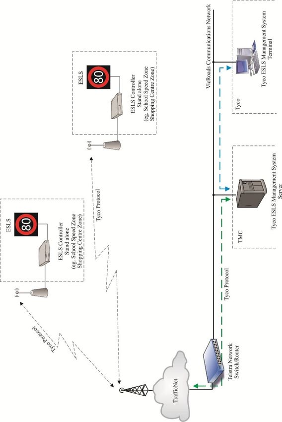
A1.1 The ESLS Network Management System (NMS) is a monitoring/management system
developed by Johnson Controls (formerly Tyco) used to monitor ESLS devices connected to
the VicRoads communication network. See Figure A.1 below.
A1.2 A large number of ESLS at school speed zones and strip shopping centres currently use the
ESLS Network Management System (NMS).
Figure A.1 – NMS communication/control schematic
TCS 037:2021
Page 27 of 34 Electronic Speed Limit Signs Rev. ADepartment of Transport (Roads)
A2 NMS PROTOCOLS
A2.1 There are two versions of NMS protocol currently in use. These are:
a) NMS (version 1), typically used for older legacy signs; and
b) NMS (version 2), used for all new installations and major upgrades to existing sites.
Details are available from Tyco’s document IM0002-D-0018, TSLS Protocol
Specification, VicRoads ESLS NMS.
A2.2 Copies of the NMS sign protocol specifications are available upon request from the DoT
(Roads).
TCS 037:2021
Page 28 of 34 Electronic Speed Limit Signs Rev. ADepartment of Transport (Roads)
APPENDIX B FAULT NOTIFICATIONS AND LOGGING
(Normative)
B1 MINIMUM REQUIRED FAULT NOTIFICATIONS
Each ESLS shall provide to NMS, as a minimum, the alarm notifications detailed in Table B.1.
Alarm Description Classification Required System
Response
GPS Invalid The sign has failed to obtain a valid Critical Display Alarm & raise a
data string from the GPS network to fault.
synchronise its internal time clock for
the past 24 hours.
GPS Fail The sign has failed to obtain any Critical Display Alarm & raise a
data from the GPS network for the fault.
past 24 hours.
Calendar No calendar present in the sign Critical Display Alarm & raise a
fault.
Processor Watchdog The sign processor has flagged a Critical Display Alarm & raise a
watchdog alarm. fault.
Processor or The sign processor or system has Critical Display Alarm & raise a
System Failure failed. fault.
Communications Failure The sign has stopped Critical Display Alarm & raise a
communicating with the fault.
management system.
Power Supply Failure The sign has lost internal power. Critical Display Alarm & raise a
fault.
Mains Failure The external power source to the Critical Display Alarm & raise a
sign has failed. fault.
Solar Panel Failure The solar panel has stopped Critical Display Alarm & raise a
operating. fault.
Solar panel tamper The solar panel has been moved. Critical Display Alarm & raise a
fault.
Battery Level Warning 1 The battery has 24 hours of charge Critical Display Alarm & raise a
left. fault.
Battery Level Warning 2 The battery has less than 6 hours Critical Display Alarm & raise a
charge left. fault.
Battery Failure The battery has failed or has less than 2 Critical Display Alarm & raise a
hours charge left. fault.
Battery Overcharge The battery is overcharged or Critical Display Alarm & raise a
exceeded maximum operating fault.
temperature.
Excessive The internal temperature of the sign Critical Display Alarm & raise a
Internal has exceeded the maximum safe level fault.
Temperature for the internal components.
Display shut 20% of the LED’s in a numeral Critical Display Alarm & raise a
down - have failed and the sign has fault.
Numerals shutdown.
Table B.1 - Minimum required fault notifications
TCS 037:2021
Page 29 of 34 Electronic Speed Limit Signs Rev. ADepartment of Transport (Roads)
Alarm Description Classification Required System
Response
Display shut 20% of the LED’s in the annulus Critical Display Alarm & raise a
down - Annulus have failed and the sign has fault.
shutdown.
Facility Switch Facility switch has been set to a Critical Display Alarm & raise a
– Not in AUTO set speed. fault.
position
Facility Switch Facility switch has been turned to Critical Display Alarm & raise a
– OFF the ‘OFF’ position. fault.
Door The sign door is open Critical Display Alarm & raise a
fault.
Tilt The sign is no longer vertical Critical Display Alarm & raise a
fault.
Surge Surge Protection device is low or Minor Display Alarm & raise a
Protection failed fault.
Table B.1 (continued) - Minimum required fault notifications
B2 MINIMUM LOGGING REQUIREMENTS
B2.1 Each Sign shall provide internal fault logging for all fault events detailed in Table B1, with a
minimum history of 500 entries.
B2.2 In addition, each Sign shall provide internal event logging for all events detailed in Table B2
with a minimum history of 500 events.
Entry Description Classification
10% LED failure - 10% of the LED’s in annulus have failed. Sign display
Annulus fault/status
Dimming mode Automatic or manual dimming mode Sign status
Luminance level Current luminance level Sign status
Luminance controller Sign luminance controller failure Sign fault/status
failure
Sign time Current sign time in seconds Sign status
Firmware version Current sign firmware of the sign Sign status
Sign manufacturer Sign manufacturer Sign status
Sign model Sign model Sign status
Critical error The sign is disabled due to a critical error and Sign status/error
hasn’t been overridden or cleared to run
automatically by an operator or technician
Table B.2 - Minimum logging requirements
TCS 037:2021
Page 30 of 34 Electronic Speed Limit Signs Rev. ADepartment of Transport (Roads)
Entry Description Classification
Sign up time The time/duration of continuous operation of the Sign status
sign
Sign rings Number of rings of in the annulus to flash Sign status
Control mode Manual or automatic sign operation mode Sign status
Door Sign open door alarm Sign status/alarm
GPS status Current status of GPS Sign status
Site ID Site ID of the sign Sign status
Sign ID ID allocated to the sign Sign status
Temperature Current temperature of the sign Sign status
Phone number Phone number of the sign’s sim card Sign status
Number of signs in Number of signs in Group Sign status
Group
Solar current Solar current measurement Sign status
Battery status Current battery measurement Sign status
Voltage level Current battery voltage measurement Sign status
Internal Internal communications failure Sign status/error
communication error
Display time-out Sign display time-out Sign status/error
Master/Slave comms Master/Slave comms failure Sign status/error
failure
Watchdog The sign processor has flagged a watchdog alarm. Sign status/error
Table B.2 (continued) - Minimum logging requirements
TCS 037:2021
Page 31 of 34 Electronic Speed Limit Signs Rev. ADepartment of Transport (Roads)
APPENDIX C GUIDELINES FOR PURCHASING AND
INSTALLATION
(Informative)
DETAILS TO BE INCLUDED WHEN TENDERING
C1 Installation requirements will be site specific and detailed in individual tender documents.
C2 The following details should be considered when preparing tender documents:
a) The size of the proposed signs, i.e. whether A, B or C size.
b) Whether single speed, dual speed or multiple speed.
c) Which side the door is required to hinge from.
d) Whether the proposed signs are mains or solar powered.
e) Requirements for battery backup.
f) Whether the display is discrete or a matrix.
g) The numbers of signs and speed values to be provided.
h) The mounting arrangements for the signs;
TCS 037:2021
Page 32 of 34 Electronic Speed Limit Signs Rev. ADepartment of Transport (Roads)
APPENDIX D REQUIREMENTS FOR TYPE APPROVAL
(Normative)
D.1 GENERAL
D1.1 Electronic Speed Limit signs for use on VicRoads projects are required to hold current
VicRoads Type Approval.
D1.2 The Product Compliance evaluation process shall be carried out in accordance with VicRoads
Guideline TCG 016.
D1.3 To enable assessment for the purpose of granting Type Approval, the manufacturer/supplier
is to submit a formal request for Type Approval, for each sign type submitted, accompanied
by the following:
• A complete working sample of the sign.
• An outline drawing showing the general presentation and overall dimensions of the
complete sign.
• Documentation to demonstrate that the sign has been manufactured and supplied under
an approved quality assurance system.
• Documentation to demonstrate that the sign conforms to the requirements of VicRoads
Specification. This may be by means of submitting test results from approved and
appropriately qualified independent testing organisations, or providing the manufacturer’s
assurance that the product complies with each paragraph of the specification, as
appropriate.
D2 REQUIRED NATA ACCREDITED TESTING
Notwithstanding F1 above, the manufacturer/supplier shall submit test results from a NATA accredited
(or equivalent), testing organisation to demonstrate compliance with the following.
AS 5156 Clause Requirement
4.6.1 EMC Immunity
4.6.2 EMC Emissions
5.2.1 Luminance and luminance ratio
5.2.2 Luminance matching of colours
5.2.3 Luminance intensity uniformity
5.2.4 Colours (chromaticity)
7.1 Temperature and humidity
7.2 Enclosure protection for sign enclosure
7.4 Vibration
D3 COMPATIBILITY WITH NMS
D3.1 ESLS intended to be connected to the NMS must be fully compliant and compatible.
D3.2 To ensure compliance the supplier shall obtain a compliance certificate prior to operation on
the NMS.
TCS 037:2021
Page 33 of 34 Electronic Speed Limit Signs Rev. ADepartment of Transport (Roads)
D3.3 A copy of this certification shall be provided to VicRoads.
D4 OTHER REQUIRED INFORMATION
D4.1 Confirmation that the manufacturer is on the VicRoads Register for the Pre-qualification for
Supply of On-Road Electronic Devices.
D4.2 Copy of LED manufacturer’s specification for each LED type used.
D5 ASSESSMENT PROCEDURE
D5.1 The assessment procedure for an ESLS may include, but not limited to, the following:
a) Assessment of construction, workmanship and critical dimensions.
b) Evaluation of the submitted data against the requirements of the specification.
c) Review of test reports.
d) Testing on NMS.
e) Continuous sign operation connected to NMS at the manufacturer’s premises (or other
agreed location) for a period of not less than 3 months.
D5.2 Where some of these procedures have been completed prior to formal submission, the results
will be considered in the evaluation, provided there is no relevant change in the design of the
sign.
D5.3 The supplier is to state whether tests carried out prior to formal submission were carried out
on an identical sample of the sign.
D5.4 DoT (Roads) may require a field trial of the sign to be undertaken.
D6 TYPE APPROVAL
D6.1 The decision to grant a Certificate of Type Approval is at the sole discretion of VicRoads.
D6.2 VicRoads may require additional information or testing to be carried out as part of its
evaluation of the product.
D6.3 If the product is approved, a Certificate of Type Approval will be provided to the supplier.
Until such time as this Certificate is issued, the product is not to be used for VicRoads works.
TCS 037:2021
Page 34 of 34 Electronic Speed Limit Signs Rev. AYou can also read