Alphatron SSRS Sound Reception System Installation and Operation Manual - www.jrc.am
←
→
Page content transcription
If your browser does not render page correctly, please read the page content below
Alphatron SSRS
     Sound Reception System
Installation and Operation Manual
           www.jrc.am
Contents

I Preface.......................................................................................................... 4
   I.1 Revision History........................................................................................................................................................ 4
   I.2 Glossary.................................................................................................................................................................... 4
       I.2.1 Abbreviations.................................................................................................................................................... 4
       I.2.2 Standards......................................................................................................................................................... 5

II Cautions...................................................................................................... 7

III Introduction................................................................................................ 8
   III.1 Product Description................................................................................................................................................. 8
   III.2 System Description................................................................................................................................................. 8

1 Installation................................................................................................. 10
   1.1 Microphone Unit..................................................................................................................................................... 10
   1.2 Display Unit............................................................................................................................................................ 12

2 Operation................................................................................................... 14
   2.1 Operational Modes................................................................................................................................................. 14
       2.1.1 Normal Mode.................................................................................................................................................14
       2.1.2 Manual Listening Mode.................................................................................................................................15
       2.1.3 Calibration Detection Mode...........................................................................................................................16
       2.1.4 LED Test Mode............................................................................................................................................. 16
   2.2 Network Operations................................................................................................................................................17
       2.2.1 PJTR Sentence............................................................................................................................................. 17
           2.2.1.1 SRS Proprietary Sentence................................................................................................................... 18
           2.2.1.2 VOL Proprietary Sentence................................................................................................................... 18
           2.2.1.3 HBT Sentence...................................................................................................................................... 19
       2.2.2 DDC Sentence.............................................................................................................................................. 19
       2.2.3 Maximum Data Rates................................................................................................................................... 20
   2.3 Syslog Messages................................................................................................................................................... 20
   2.4 Audio Packet Stream............................................................................................................................................. 20
   2.5 Error Indicator........................................................................................................................................................ 21
   2.6 Detecting a Sound Signal...................................................................................................................................... 22
   2.7 Detecting Multiple Sound Signals.......................................................................................................................... 23
   2.8 Adjusting Volume and Lighting.............................................................................................................................. 24
   2.9 Web Interface.........................................................................................................................................................24
       2.9.1 Home Screen................................................................................................................................................ 25
       2.9.2 Network Settings........................................................................................................................................... 27
       2.9.3 Audio Settings............................................................................................................................................... 29
       2.9.4 System Log................................................................................................................................................... 30
       2.9.5 Additional Options......................................................................................................................................... 32
   2.10 Testing..................................................................................................................................................................33
       2.10.1 Calibration and Testing............................................................................................................................... 33

3 Specifications............................................................................................34

  2 | Contents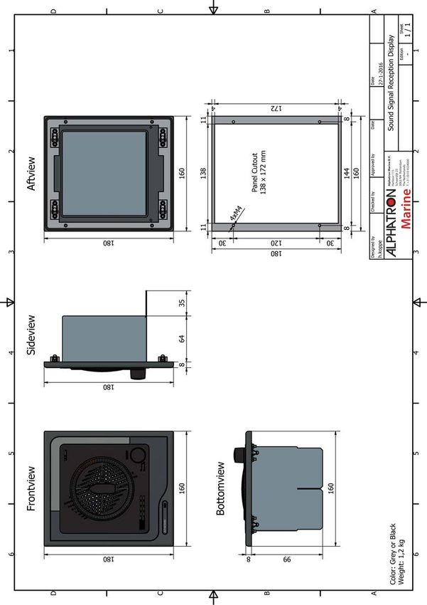
4 Maintenance.............................................................................................. 35
   4.1 Troubleshooting...................................................................................................................................................... 35
       4.1.1 Microphone Surveillance Failure...................................................................................................................35
       4.1.2 LED Surveillance Failure.............................................................................................................................. 36
       4.1.3 Fog Horn Detection Failure.......................................................................................................................... 36
       4.1.4 Display Device Boot Failure..........................................................................................................................36
   4.2 Service....................................................................................................................................................................36
   4.3 Spare Parts............................................................................................................................................................ 37
   4.4 Recycling and Disposal..........................................................................................................................................37
   4.5 Test and Maintenance Records.............................................................................................................................38

5 Drawings....................................................................................................39
   5.1   SSRA Microphone Unit.......................................................................................................................................... 39
   5.2   SSRD Display........................................................................................................................................................ 40
   5.3   Connection Diagram Microphone Unit...................................................................................................................41
   5.4   Connection Diagram Display................................................................................................................................. 42
   5.5   Cable Diagram....................................................................................................................................................... 43

  3 | Contents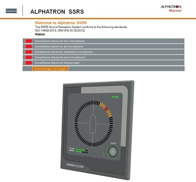
I Preface
The Alphatron SSRS sound reception system has been designed to make sound signals from other ships audible by
personnel whilst they are in the fully enclosed bridge space. The system complies with all the latest applicable standards
and has been tested with the most modern test instrumentation and detailed test procedures ensuring a top quality
product.
All information contained in this manual has been verified for correctness however, no responsibility is assumed by
Alphatron for inaccuracies. Alphatron does not assume any liability arising out of the application or use of the described
product.

I.1 Revision History
Revision No.          Description                                                Date
V0.9                  Preliminary                                                17 March 2016
V1.0                  First Issue                                                28 April 2016
V1.1                  Changed article nr.'s Cable Diagram                        10 may 2016
V1.2                  Changed Connection diagram                                 17 January 2020

I.2 Glossary
The Glossary contains a list of commonly used abbreviations and a list of applicable standards.

I.2.1 Abbreviations

Abbreviation          Meaning
CMOS                  Complementary Metal-Oxide Semi conductor
ESD                   Electrostatic Discharge
DDC                   Display Dimming Control (sentence)
DHCP                  Dynamic Host Configuration Protocol
HBT                   Heartbeat (sentence)
HTTP                  Hypertext Transfer Protocol
Hz                    Hertz (unit of frequency)
IC                    Integrated Circuit (system)
IEC                   International Electrotechnical Commission
IMO                   International Maritime Organization
IP                    Internet Protocol (address)
ISO                   International Organization for Standardization
kB/s                  Kilobytes per second
kHz                   Kilohertz
LED                   Light-Emitting Diode
PCM                   Pulse Code Modulation
PJTR                  Jotron Proprietary Sentence
RMA                   Return Material Authorization number

  4 | Preface
Abbreviation          Meaning
RTCP                  Real-time Transport Control Protocol
RTP                   Real-time Transport Protocol
SFI                   System Function ID
SOLAS                 Safety of Life at Sea
SPL                   Sound Pressure Level
SRS                   Sound Reception Signal (proprietary sentence)
VDC                   Voltage Direct Current
VOL                   Volume (proprietary sentence)

Table 1: Abbreviations

I.2.2 Standards
The Alphatron SSRS Display Unit has been verified, tested and meets the product standards as listed in Table 2:
Standards on page 5

Standard                 Description
ISO 14859:2012           Ships and marine technology - Sound reception systems:
IEC 60945:2002           Maritime navigation and radio communication equipment and systems - General
                         requirements - Methods of testing and required test results.
IEC 61162:2010-1         Maritime navigation and radio communication equipment and systems – Digital interfaces -
                         Part 1: Single talker and multiple listeners.
IEC 61162:2011-450       Maritime navigation and radio communication equipment and systems - Digital interfaces -
                         Part 450: Multiple talkers and multiple listeners - Ethernet interconnection.
IEC 62288 Edition        Maritime navigation and radio communication equipment and systems – Presentation of
2:2014                   navigation-related information on shipborne navigational displays – General requirements,
                         methods of testing and required test results.

Table 2: Standards

The Alphatron SSRS Display Unit also fulfills the requirements as listed in Table 3: Requirements on page 5

Requirement           Description
SOLAS Chapter         Carriage requirements for shipborne navigational systems and equipment.
V - Safety of
navigation -
Regulation 19
IMO Res.              General requirements for shipborne radio equipment forming part of the Global Maritime
A.694(17)             Distress and Safety System (GMDSS) and for electronic navigational aids.
IMO Res.              Adoption of the international code of safety for high speed craft (1994).
MSC.36(63)
IMO Res.              Adoption of new and amended performance standards for navigational equipment.
MSC.86(70)

  5 | Preface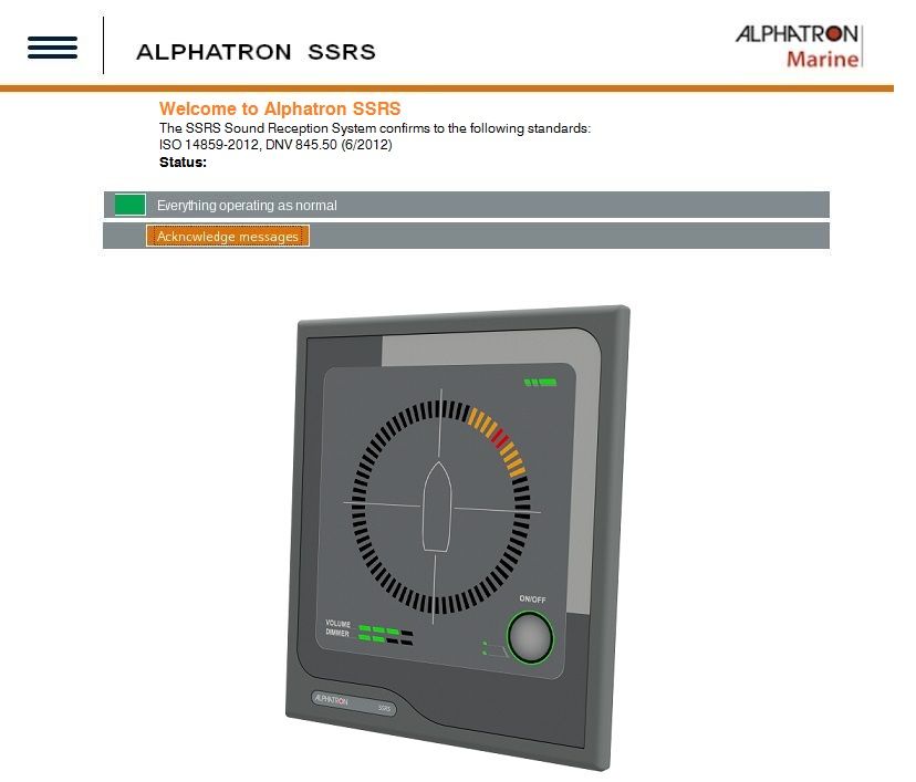
Requirement        Description
IMO Res.           Adoption of the international code of safety for high speed craft (2000).
MSC.97(73)
IMO Res.           Performance standards for the presentation of navigation-related information on the shipborne
MSC.191(79)        navigational displays.

Table 3: Requirements

      Note This product is also ship wheel-mark and type approval of marine products certified in accordance with
      Marine Equipment Directive (MED).

  6 | Preface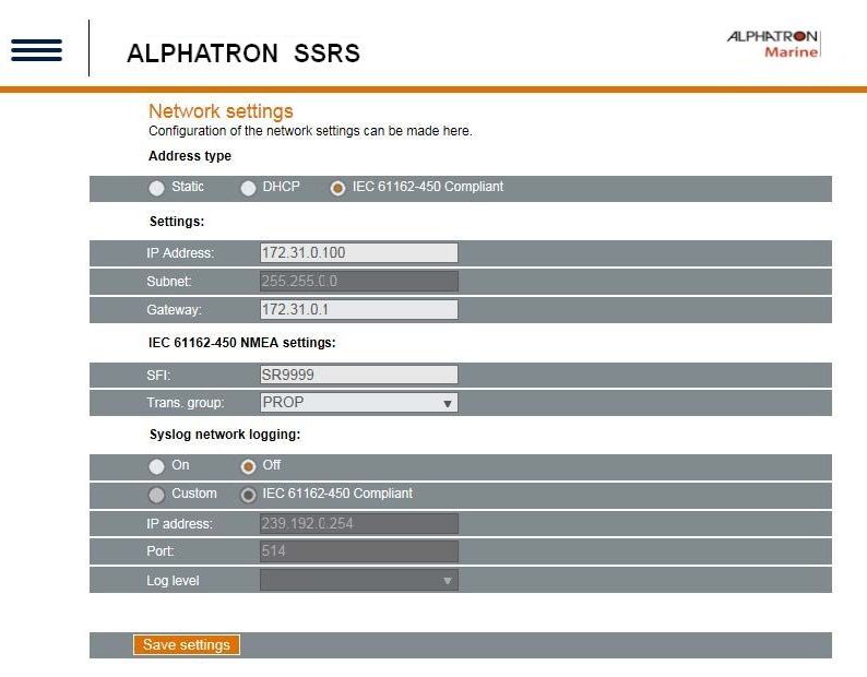
II Cautions
The following symbols are used in this manual regarding safety:
       •   Caution damage.
       •   This symbol is used to highlight information that if not followed can result in damage to a product or
           equipment.
       •   Warning injury / death
       •   This symbol is used to highlight information that if not followed can result in personal injury or death.

  7 | Cautions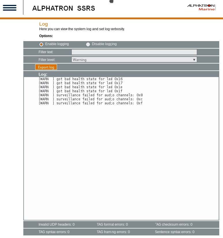
III Introduction
III.1 Product Description
The Alphatron SSRS sound reception system has been designed to:
•   Receive and detect fog horn sounds from other vessels and pinpoint the direction of the signal source.
•   Detect signals with a fundamental frequency ranging from 70 Hz to 820 Hz.

Detected horns are amplified and played through the speaker on the display unit and the direction of the signal source
appears on the display, with an accuracy of +/- 10 degrees. The Alphatron SSRS has adaptive background noise
canceling to filter out unwanted sounds through advanced digital signal processing. Multiple display units can share the
same microphone unit through an Ethernet connection.
Part Numbers
For part numbers refer to Spare Parts on page 37
        •   Caution: Electrostatic Devices
        •   This equipment contains CMOS integrated circuits. Observe precautions for handling electrostatic sensitive
            devices. Electrostatic discharge (ESD) may damage this equipment.

Figure 1: Product Image Display                              Figure 2: Product Image Microphone

III.2 System Description
A sound reception system is an acoustical electronic navigational aid that enables an individual to hear sound signals
from other ships like fog horns when standing inside a totally enclosed bridge space. This is to perform the look-out
function as required according to the International Regulations for Preventing Collisions at Sea, 1972.
The system works by listening and detecting the direction of a fog horn. The Alphatron SSRS system is always listening
for sounds on the outside of the ship and will only playback and display sounds once a horn has been detected. The
ship's own horn can be suppressed by closing a closing contact on the Alphatron SSRS system, which will disable
detection for the duration it is held closed.

    8 | Introduction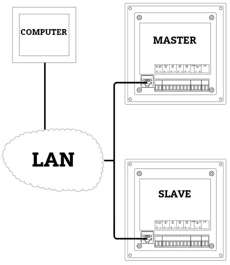
Figure 3: Sound Reception System

 9 | Introduction

1 Installation
1.1 Microphone Unit

Figure 4: Top Mounted                                          Figure 5: Side Mounted

1. Fasten the microphone with the attached mounting bracket to the ship, or remove the bracket and attach the steel
   tube by other means.

           Note The mounting bracket can be mounted to a ship by the top or the side.

           Note The "Fore" direction of the microphone unit is marked with an arrow and should be pointing towards the
           bow of the ship when installed.
           •   Caution: Install the Microphone Unit in an appropriate location and ensure the following:
           •   Install in a location far away from noise and any mechanical vibration sources.
           •   Do not install the microphone next to a sound reflective source or obstacle that may block sound from
               entering the microphone unit in a straight line.
           •   Install the microphone unit in a typical lookout position.
2. Wire the cables from the microphone unit to a junction box suited to the environment it is placed in.

           Note The cables are 3 meters long with flying leads.

3. Lay a cable from the junction box to the display unit. See Figure 38: Cable Diagram on page 43.
4. Terminate the cable in the 11 pin microphone connector at the back of the display unit when connecting the
   microphone to the display unit. See Figure 36: Connection Diagram SSRA on page 41

  10 | Installation
The cable must be shielded and contain at least 5 twisted pairs made of bare copper and have a lead core size of 0.25mm2 or larger when the cable length is up to 100m. If a longer stretch of cable is required (up to a maximum of 200 m), use a lead core size of 0.5mm2 or larger. Figure 6: Wiring Schematic WH White Port + BN Brown Port - GN Green Aft + YE Yellow Aft - GY Grey Strb + PK Pink Strb - BU Blue Fore + RD Red Fore - BK Black GND VT Violet Vinn 11 | Installation
Note Clarification of the notes in Connection Diagram: (Figure 6: Wiring Schematic on page 11).
        1. Refer Cable and Connection Diagrams regarding supply of cables. The cable must be shielded with individual
           pairs and have a minimum 0.25mm2 core size.
        2. A junction box is optional and can be supplied by Alphatron.
        3. To comply with EMC requirements, all cable screens must be safely connected to chassis as shown in Figure
           6: Wiring Schematic on page 11.
        4. To mute signal to the Alphatron SSRA. A closing contact (NO) will mute the sound reception system while
           closed. Generally, this input is used by the ship's Typhoon system.

Figure 7: Ethernet Electrical Connections

The set up for the master/slave, web interface via a computer or connection to an IEC 61161-450 network is as shown
above.
        Note The cable must be a minimum of Cat. 5 S/UTP quality. Master/Slave can be connected directly together or
        via a LAN switch.

1.2 Display Unit
Install the display unit in such manner that incoming sounds signals and incoming sounds can be heard at all positions
inside the bridge and are visible from the conning position.
        Note Prior to fastening the unit to a console the power and microphone unit connectors must be connected,
        unless the device is used as a slave device to another display unit.

  12 | Installation
Figure 8: Place Frame on Cutout Figure 9: Screw Fix Frame
Figure 10: Place Display Unit Figure 11: In Place
1. Mount the display unit in a bridge console, or similar structure.
Note Plug in the Ethernet cable, if the network features of the display unit will be used.
2. Screw fix the frame with four screws to the cutout where the Display Unit is to be placed.
Note Screws are provided.
3. Place the Display Unit into the cutout and firmly press down on the four corners.
Note Snap-on clips are located on the back of the Display Unit, which fit exactly into the four holes provided
in the mounting plate. See Figure 35: SSRD Display on page 40.
To remove the display firmly grip the panel with the tops of the fingers and pull backwards and up at the same time. Do
not use screwdrivers as these will damage the display cover and paint work of the console.
The display unit has a mute closing contact, this can also be attached to the fog horn system on the ship. This contact
suppresses detection when the contact is closed and begins again when it is open.
Advanced configuration options can be performed using the web interface.
13 | Installation2 Operation
2.1 Operational Modes
The Alphatron SSRS display unit has four different operational modes.
Figure 12: Normal Mode, Idle.
Press and hold the CONTROL rotary button for 5 seconds, to switch between modes.
Note Keep the button depressed to advance to the next mode. The mode will change every 5 seconds.
2.1.1 Normal Mode
When the Alphatron SSRS is first started it will start in the normal mode. When in this mode the unit will idle until a horn
signal is detected. Detected horns are audible from the speaker and indicate the direction of the source of the signal.
Within the first 3 seconds of detection an 80 degree arch will light up in orange, while the center of the arch is lit in red.
After having been on for 3 seconds the red light remains active. Multiple indications can be active at once. The indication
pointer will remain for a configurable amount of time (7 seconds by default), after the detection is finished. The indication
pointer configuration time can be altered within the web interface.
The light behind the CONTROL button is off when the unit is in this mode.
The volume and lighting can be adjusted. To adjust the volume or lighting, perform the following actions:
1. Press the CONTROL button until the option you wish to adjust is orange.
2. Rotate the CONTROL button to observe the volume or dimmer changes.
Note The active adjustment line is lit up orange and the inactive line is lit up green. This is also indicated by
the lights on the left of the control button.
14 | Operation2.1.2 Manual Listening Mode
Figure 13: Selecting the Fore Microphone Figure 14: Selecting the Aft Microphone
In the manual mode each of the four microphones can be listened to individually. In this mode the sound from the active
microphone is audible through the speaker at all times.
To activate the manual listening mode, perform the following actions:
1. Press and hold the CONTROL button for 5 seconds when in the normal mode.
When active the light around the CONTROL button appears green.
2. Rotate the CONTROL button to select the Fore microphone.
Note Neither the volume nor dimmer row is lit orange when the microphone is selected.
3. Rotate the CONTROL button to select the Aft microphone.
Note When the device first enters the manual listening mode it activates the 'Fore' microphone. The current
active microphone is displayed on the indication ring with the active LEDs indicating the direction of the
microphone that is active.
15 | Operation2.1.3 Calibration Detection Mode
Figure 15: No Offset (0°) Figure 16: Offset 30°
Use the calibration detection mode to adjust the offset display. For example to adjust the offset of an incorrectly mounted
microphone unit.
1. Press and hold the CONTROL button for 10 seconds.
When the calibration mode is activated the light behind the CONTROL rotary button changes to orange.
Note If the unit is in the manual listening mode, the CONTROL button only has to be pressed and held for 5
seconds.
2. Rotate the CONTROL button to calibrate the position, to add (right) or subtract (left) the offset for all detections.
The current offset is indicated by the indication LEDs. A more precise offset can be set in the web interface.
Note The default is a zero degree offset and a single tick with the CONTROL button will adjust the offset by
10 degrees.
2.1.4 LED Test Mode
To enter the LED test mode, perform the following actions:
1. Press and hold the CONTROL button for 15 seconds, when in normal mode.
All LEDs on the display unit will light up when enabled, making any failed LEDs visible.
Note If the manual listening mode is active, press and hold the CONTROL button for 10 seconds.
Note If the calibration detection mode is active, press and hold the CONTROL button for 5 seconds.
2. Hold the CONTROL button depressed for another 5 seconds to return to normal operation..
Note The LED test mode will automatically return to normal mode if the CONTROL button is not pressed or
rotated for 30 seconds.
16 | Operation2.2 Network Operations
The Alphatron SSRS performs multiple network operations according to part 450 of the IEC 61162 standard. This
includes inter-device communication and logging.
The transmission groups are mapped to the following multicast addresses and ports:
Transmission group Address port combo:
MISC 239.192.0.1:60001
PROP 239.192.0.8:60008
USR1 239.192.0.9.60009
USR2 239.192.0.10.60010
USR3 239.192.0.11.60011
USR4 239.192.0.12.60012
USR5 239.192.0.13.60013
USR6 239.192.0.14.60014
USR7 239.192.0.15.60015
USR8 239.192.0.16.60016
Table 4: Transmission Groups
Note These transmission groups are defined in part 450 of the IEC 61162 standard.
Multiple IE 61162-450 sentences are sent and received by the Alphatron SSRS display device.
List of the applicable sentences:
• PJTR sentences (SRS proprietary sentences and VOL proprietary sentences)
• HBT sentences
• DDC sentences
Note For more information or clarification regarding these sentences, refer to IEC 61162-450.
2.2.1 PJTR Sentence
The PJTR sentence is a proprietary sentence that is used for communication between the master and slave Alphatron
SSRS display units.
The first parameter of this sentence is the sentence code for our proprietary sentences. The remaining parameters
depend on the sentence code that is sent.
The Alphatron SSRS has the following three proprietary sentences:
• Sound Reception Signal (SRS)
• Volume (VOL)
• Heartbeat (HBT)
17 | Operation2.2.1.1 SRS Proprietary Sentence When a sentence code of the PJTR sentence is sound reception signal (SRS), the sentence is a detection notification. This sentence is sent from master units to the configured transmission group such that slaves can receive them. The SRS sentence has three additional parameters: Description Type Direction of the detection An integer between 0° and 359° inclusive. Score of the detection Score with decimal point if needed. Base frequency of the detected signal Frequency with decimal point if needed. Figure 17: Example, SRS proprietary sentence 2.2.1.2 VOL Proprietary Sentence When a sentence code of the PJTR sentence is volume (VOL), the sentence is a volume adjustment notification. This sentence is sent from both the master and the slave units when the volume is adjusted using the CONTROL button on the display unit. The sentence is sent on the configured transmission group. When an Alphatron SSRS display unit receives such a message it will automatically adjust the volume to match the volume of the device that sent the sentence. The VOL sentence has one additional parameter: Description Type New volume setting An integer between 0 and 99 inclusive. Figure 18: Example, VOL proprietary sentence 18 | Operation
2.2.1.3 HBT Sentence
The Alphatron SSRS sends a heartbeat (HBT) sentence once every 60 seconds. This sentence is sent to the MISC
transmission group. It is equal to the standard HBT sentence, except that it is sent as a parameter to the PJTR sentence.
        Note Refer to IEC 61162-1 standard for more information regarding heartbeat sentence.

Figure 19: Example, HBT sentence

2.2.2 DDC Sentence
The Alphatron SSRS display unit listens for display dimming control (DDC) sentences sent from any other unit on the
network, that sends on the MISC channel, or uses the same transmission group as configured in the web interface
network settings.
When a DDC sentence is received, the display device will adjust the brightness to the new level received.
Two variants of the DDC messages are supported; one with and one without the sentence status parameter at the end of
the sentence.
        Note Refer to IEC 61162-1 standard for more information regarding the two variants and the DDC sentence.

Figure 20: Example, DCC sentence

        Note The two dashes before the DDC message represents the sender and can be any two upper case
        characters from A-Z.

  19 | Operation
2.2.3 Maximum Data Rates
These are the maximum data rates as required by 61162-450, section 4.3.2:
Description Amount
Maximum received per second, intended for target 50/sec
Maximum received per second, not intended for target 2000/sec
Maximum received per second, not intended for target at 50% of the maximum load. 1000/sec
Table 5: Maximum Data Rates
2.3 Syslog Messages
When Syslog network logging is enabled, Syslog messages are sent to the network address specified in the web
interface (seeTable 6: Syslog Messages on page 20. Refer to the network settings for more information.
Message ID Message text Additional information
SURV_AUDIO_FAILURE Surveillance failed for audio is replaced with a bitmask in hex of the
channels: channels that have failed audio surveillance. Available
channels:
• 0x1 Fore
• 0x2 Aft
• 0x4 Starboard
• 0x8 Port
For example, 0xC indicates a failure of port and
starboard microphones.
SURV_LED_FAIL Bad health state of LED
SURV_WDOG_NOT_ Not feeding watchdog Message informing that the unit will restart due to
FEEDING because all required tests a failing watchdog test. is replaced with a
have not been passed: bitmask in hex that identifies the failing test. Tests
include:
• 0x1 Audio surveillance test
• 0x2 DSP surveillance test
• 0x4 Display response surveillance test
Table 6: Syslog Messages
2.4 Audio Packet Stream
A proprietary audio packet stream is sent together with all other network traffic.
This stream contains the audio data from a detected fog horn signal. A master device sends the data to the multicast
group at 239.192.0.65 on port 5004 and 5005. This audio packet stream is an RTP stream with RTP data on port 5004
and RTCP data on port 5005. The audio is sent as a single channel 24 bit signed PCM at a 24 kHz sampling rate. The
RTP stream uses a packet size of 20 ms.
An audio stream is only sent when a fog horn is detected and stops when the detection ends.
The maximum bandwidth used by this stream is 96 kB/s, with approximately 50 packets per second.
20 | Operation2.5 Error Indicator
When an error is detected, the status LED on the Phontech 8300 MkII will light up orange.
Figure 21: Indicating an error has been detected.
Note For more information regarding potential failures or issues, refer to the tips explained under
Troubleshooting. (Troubleshooting on page 35)
21 | Operation2.6 Detecting a Sound Signal
Figure 22: Sound Signal as it is Detected Figure 23: Sound Signal 3 sec. after Detection
When the Alphatron SSRS detects a sound signal and determines the direction of the signal, the direction will appear on
the display unit.
After 3 seconds the orange LEDs disappear and the red LEDs remain. The red LED indicator remains by default for 7
seconds or the configured amount of time.
Note The display timing (in seconds) can be adjusted from the web interface.
22 | Operation2.7 Detecting Multiple Sound Signals The Alphatron SSRS is able to detect multiple sound signals simultaneous. One detection at 0˚ and another at 310˚. Figure 24: Detecting Multiple Sound Signals, 0° and Figure 25: Detecting Multiple Sound Signals 3sec. 310° after Detection 23 | Operation
2.8 Adjusting Volume and Lighting
Both the volume and display lighting (LED’s) of the Alphatron SSRS are adjustable.
        Note An orange LED displays the active state. This is also indicated by the lights on the left of the control
        button.

Figure 26: Volume Adjusting Mode                                Figure 27: Dimming Adjusting Mode

To adjust the volume, perform the following actions:
1. Press and release the CONTROL button to select the volume adjust mode.
2. Rotate the knob clockwise to increase and counterclockwise to decrease the volume.

   INFO: To adjust the LED light intensity, do the following:
3. Press and release the control button to select the dimming adjust mode.
4. Rotate the knob clockwise to increase and counterclockwise to decrease the LED intensity.

           Note The nominal viewing and listening distance is 0,8m.

2.9 Web Interface
The Alphatron SSRS has a web interface for logging and configuring the unit, this web interface also supplies information
regarding the state of the unit.
1. Enter the Alphatron SSRS IP address into any web browser to access the web interface.

           Note The default IP address is: 172.31.0.100, with a netmask of 255.255.255.0.

   A prompt appears to enter user name and password the first time the web interface is accessed. The default user
   name and password are: admin / admin.
2. Click or hover with the mouse over the striped button to navigate between pages.

  24 | Operation
Note This button activates the navigation menu where you can access the pages. The active page is marked
orange with a white arrow pointing to it.
Note Some changes require a reboot of the device, in this case, the web interface will display a message
indicating that a reboot is necessary. This is done in Additional options and is explained under Maintenance.
2.9.1 Home Screen
The home screen is the first page shown when the web interface is accessed on the Alphatron SSRS. This screen
displays the status of the unit.
Figure 28: Home Screen Status OK
The following information appears in the Status section of the screen:
Status Notification colour Text description
Normal Green Everything operating as normal
Error detected Red A message describing the error
Note If an error has been observed and attended to, then the ACKNOWLEDGE MESSAGES button can be
pressed to clear the status led on the display (Figure 29: Home Screen, Status Failed - Acknowledge Messages
on page 26).
25 | OperationFigure 29: Home Screen, Status Failed - Acknowledge Messages 26 | Operation
2.9.2 Network Settings
The following network settings can be configured:

Configurable             Description:
network settings
Network address of       1. Static - this option allows any static network address to be configured along with the
the device (3 options)      applicable netmask and gateway.
                         2. DHCP - this option will request the DHCP server for an address, either when the unit is
                            started, or when a network cable is plugged in.
                         3. IEC 61162-450 complaint static address - this option restricts the address to an
                            address within the range of: 172.16.0.0 - 172.31.255.255. In this mode netmask is
                            not configurable and forces the 255.255.255.0 configuration. The gateway is freely
                            configurable with this option.

IEC 61162-450            Configure the transmission group used for sending and receiving messages by selecting
settings                 from the PROP or USR1-USR8 groups.
Syslog settings          The device logging over network can be enabled through the Syslog protocol. By enabling
                         the Syslog network logging, the Alphatron SSRS will send information and error messages
                         over the Ethernet network. Syslog messages can either be sent to the IEC 61162-450
                         compliant address (239.192.0.254:514), or a user can configure a custom server address
                         by changing the IP address and port fields in the Syslog section. To change the messages
                         that are logged, ensure the log level setting is changed in the same section. The options
                         range from Debug to Emergency priority. When this is set, all messages at the selected
                         level or higher will be sent to the Syslog server.

       Note The default is an IEC 61162-450 complaint address of 172.31.0.100.

       Note Prior to using the Alphatron SSRS on a IEC 61162-450 network to send sentences to other units, an SFI
       address must be configured. The configuration value for the address must start with SR and be followed by 4
       digits, for example SR9999.

  27 | Operation
Figure 30: Network settings - overall configuration To configure the network settings, perform the following actions: 1. Select the address type. 2. Enter the applicable settings. 3. Enter the applicable IEC settings. 4. Select the Syslog network options. 5. Click the Save settings button. 28 | Operation
2.9.3 Audio Settings
The audio settings of the Alphatron SSRS allows the signal to noise ratio required to be adjusted, prior to a fog horn
being detected. The default value is 2.25 is calibrated to handle a fog horn where the bulk of the energy lies between
700-2100 Hz from 0.5 nautical miles when a horn creates a 115 dB SPL sound level.
The signal to noise ratio configuration ranges from 2 to 6. The higher the values the stricter the Alphatron SSRS will be in
detecting horns. Lower values will detect more horns, but are more susceptible to false detections.
To configure the signal to noise ratio, perform the following actions:

Figure 31: Audio settings - signal to noise ratio.

1. Use the slider, or manually type in a value.
2. Click the SAVE SETTINGS button.

  29 | Operation
2.9.4 System Log
The Alphatron SSRS has a logging feature that enables logging in several levels. The system log page displays a real
time log of the system, in addition to previously generated messages.
To view logs, perform the following actions:

Figure 32: Event Logging

•   To view logs click the Enable logging radio button.
    Log messages will appear in the Event Logging window.
•   To search or filter a log use the Filter text or Filter level settings.
    Displays only log lines that contain a phrase or are as important as the given log level.
    There are counters recording the number of IEC 61162-450 sentence errors received. There are six different types:

    30 | Operation
Error types Description
Invalid UDP headers Packets that have been received but are lacking the required IEC 61162-450 UDP
header.
TAG format Format or structural error in the TAG block
TAG checksum Checksum errors in the TAG block.
TAG syntax Syntax error in the TAG block, such as illegal characters or fields.
TAG framing Framing errors in the TAB block, such as missing begin and/or end characters.
Sentence syntax Syntax errors in IEC 61162-450 sentences.
Note For more information regarding sentences and error types, refer to part 450 of the IEC 61162 standard.
• To export the log click the Export log button.
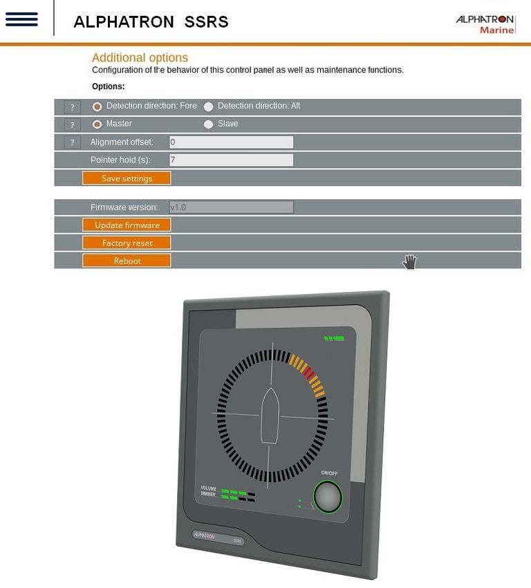
31 | Operation2.9.5 Additional Options The additional options page contains configuration options that do not fall under any of the other categories. Figure 33: Additional options To adjust any of these options, perform the following actions: 1. Select the applicable option. 2. Enter the applicable information. 3. Click the SAVE SETTINGS button. 32 | Operation
Options                            Description
    Detection direction: Fore          This is the default setting. If fore is selected, horns detected to the fore of the
                                       microphone unit will be displayed at the fore of the display unit.
    Detection direction: Aft           If aft is selected, all horns detected will be offset by 180˚ in the display unit. Horns
                                       detected to the fore of the microphone. unit will be displayed at the aft of the display
                                       unit.
    Master                             This is the default setting. The master unit must be connected to the microphone
                                       unit. The master unit will transmit all detected signals to any slave units over
                                       Ethernet.
    Slave                              The slave unit can not be connected to the microphone unit, but will receive
                                       detections and sound from the master unit over Ethernet. There may be multiple
                                       slave units in an installation.
    Alignment offset                   Use this setting to add an offset to all detections in case the microphone unit has
                                       not been mounted accurately in the fore direction.
    Pointer hold                       Use this setting to adjust the length of time a detection is displayed, after the
                                       detection has ended. The default value is 7 seconds.

             Note When working with a Master or Slave setup, all units must be:
             1. Connected to the same network.
             2. Configured with different IP addresses.
             3. Use the same transmission group.
             Note More information about the options may be viewed by clicking on the (?) question mark buttons next to the
             individual options.
The additional options page also offers the possibility to do the following maintenance:
•     Firmware updates.
•     Restore the unit to the factory defaults.
•     Reboot the system.

To complete any of the additional maintenance options, do one of the following:
•     To complete a Firmware update, click Update firmware.
•     To restore the factory defaults, click Factory reset.
•     To reboot the system, click Reboot.

2.10 Testing
Testing should be done as required.

2.10.1 Calibration and Testing
Testing of the operational functionality of the Alphatron SSRS is done using a fog horn.
             Note The Alphatron SSRS automatically and continuously tests both the display and microphone unit. In the
             event there is an error, the error will be displayed by the LED's, in the web interface or in the syslog server (if
             configured).
Horn activity should be in 3 second bursts with at least 10 seconds between each burst.
             Note If the microphone unit is not mounted correctly, the display unit can compensate for this by adding an
             offset to the detections. Check the calibration mode or additional options.

      33 | Operation
3 Specifications
Supply voltages Nominal 24VDC
Maximum power consumption 8W
System power 4W
Dimensions (W/H/D) 160mm x 180 mm x 99mm. Refer drawing:
Figure 35: SSRD Display on page 40
Weight 1.2 kg
Temperature operating -15 to +55°C
Temperature storage -15 to +55°C
Humidity 93% @ +40°C
Interfaces 100 Mbit Ethernet, Mute closing contact, Alphatron SSRS interface
Table 7: Product Specification Display Unit
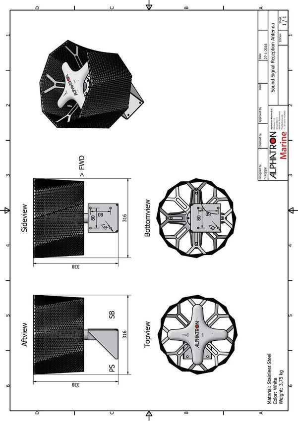
Supply voltages Powered by Alphatron SSRS+5VDC
Dimensions (W/H/D) 316mm x 338 mm x 316mm. Refer drawing:
Figure 34: SSRA Microphone Unit on page 39
Weight 3.75 kg
Temperature operating -25 to +55°C
Temperature storage -25 to +70°C
Humidity 93% @ +40°C
Table 8: Product Specification Microphone Unit
34 | Specifications4 Maintenance
All maintenance options for the Alphatron SSRS are completed in the Additional options page, web interface. The
maintenance options are as follows:
• Upgrade or view the current version of Firmware.
• Perform a factory reset.
To upgrade Firmware, do the following:
1. Click the UPDATE FIRMWARE button.
2. Select the Firmware upgrade package in the dialog box.
When the Firmware upgrade is complete, the device will automatically restart.
To perform a factory reset, do the following:
1. Click the FACTORY RESET button.
2. Click Yes in the dialog box.
Note All configuration options will be reset to the factory default, including the network IP address setting. The
default network IP address (172.31.0.100) must be entered manually in a web browser to regain access to the
web interface.
If the original default address was not changed, the web interface will refresh automatically.
When the reset is complete, the device will automatically restart.
To reboot click the REBOOT button. The device will automatically restart.
4.1 Troubleshooting
When the Alphatron SSRS device detects a problem, the front status LED will switch from green to orange.
To get an indication of what may be wrong, do one of the following:
• Check the Syslog server if Syslog network logging is enabled.
• Check the web interface of the device.
Below are tips for solving the following potential failures or issues:
• Microphone surveillance failure.
• Led surveillance failure.
• Fog horn detection problems.
• Display device boot failure.
4.1.1 Microphone Surveillance Failure
If the signal coming from one or more of the microphones on the Alphatron SSRS microphone unit is malfunctioning,
perform the following actions:
1. Check the cabling.
Note The power leads should be connected to the display unit, left side of the Mute connection. A
description of all the connectors is displayed on the back of the unit.
If the web interface indicates that all microphones are down, then the problem may be with the power cable
going to the microphone unit.
2. Check the individual microphone cabling.
Note Do this when only 1 microphone has failed.
35 | MaintenanceAfter checking restart or acknowledging the error message in the web interface. This should remove the
current error indication.
3. Inspect the unit for physical obstruction of the failing microphone.
Note If no visible obstruction of the microphone can be found, consider the unit damaged. In this case,
contact Alphatron support.
4.1.2 LED Surveillance Failure
When a LED failure is indicated start the LED test mode (LED Test Mode on page 16).
Note This should indicate which LED is failing.
If any of the red indicator LEDs have stopped working a fog horn detection might not be visible to the user, in this
event contact Alphatron support.
Refer to the additional information under LED test mode.
4.1.3 Fog Horn Detection Failure
If the unit fails to detect a fog horn, perform the following actions:
1. Check to see if there are any microphone surveillance failure messages in the web interface.
Note Refer to the additional information under Microphone surveillance failure (Microphone Surveillance
Failure on page 35).
2. Adjust the signal to the noise ration setting in the web interface.
Note Refer to the additional information under Microphone surveillance failure.
3. Do a factory reset.
Note Refer to the additional information under Microphone surveillance failure.
4.1.4 Display Device Boot Failure
If the Alphatron SSRS display unit fails to start when power is connected, press and hold the reset button on the back of
the display unit for 10 seconds.
Note Power must be connected to the unit to recover the Firmware.
• Caution - corruption.
• If the Firmware starts the device properly, do a Firmware upgrade to ensure the primary Firmware is not
corrupt.
• After upgrade, the device will restart with the primary Firmware loaded. The recovery Firmware can always
be accessed by performing this step again.
• Refer to the additional information under Additional options (Additional Options on page 32).
4.2 Service
All services such as installation, maintenance or replacement must by done by an authorized Alphatron service agent.
Note Alphatron does not accept any responsibility for the dismantling or reassembling of an Alphatron SSRS
that occurs externally from an Alphatron authorized facility and/or is handled by someone other than an
authorized, trained and certified person.
36 | Maintenance4.3 Spare Parts
Keep the original packaging. If the Alphatron SSRS needs to be shipped for servicing, it is required to be shipped in the
same packaging as when the product was first received.
Name Description Part Number
Alphatron SSRS BK Complete SSRS system - Black Color Scheme 3299.0070
Alphatron SSRS GY Complete SSRS system - Grey Color Scheme 3299.0072
Alphatron SSRD BK Display SSRS - Black Color Scheme 3299.0074
Alphatron SSRD GY Display SSRS - Grey Color Scheme 3299.0076
Alphatron SSRA Separate Microphone Antenna 3299.0078
Table 9: Part Numbers
Note Ensure that all spare parts being fitted to the Alphatron SSRS are original spare parts manufactured or
approved by Alphatron.
Any use of counterfeit spare parts will deviate from the product type approval certificates and will void the
warranty.
4.4 Recycling and Disposal
The Alphatron SSRS is not to be disposed off as normal waste and must be handled in accordance with the applicable
waste disposal regulations in the country where the equipment is used.
37 | Maintenance4.5 Test and Maintenance Records
Below is an overview of all test and maintenance activities.
Date M/T* Signature Inspection
.
.
.
.
.
.
.
.
.
.
.
.
.
.
.
.
.
.
.
.
Table 10: Test and Maintenance records
*M=Maintenance, T=Test
38 | Maintenance5 Drawings 5.1 SSRA Microphone Unit Figure 34: SSRA Microphone Unit 39 | Drawings
5.2 SSRD Display

Figure 35: SSRD Display

  40 | Drawings
5.3 Connection Diagram Microphone Unit

Figure 36: Connection Diagram SSRA

  41 | Drawings
0 1 2 3 4 5 6 7 8 9
=181A
UNIT PWR 24VD+
UNIT PWR 24VD-
PORT mic+
PORT mic-
AFT mic+
AFT mic-
STBD mic+
STBD mic-
FORE mic+
FORE mic-
PWR OUT mic-
PWR OUT mic+
MUTE
MUTE
42 | Drawings
-1P1
Display
Alphatron SSRD
1.1
2
3
4
5
6
7
8
9
10
1
2
1
1
2
Figure 37: Connection Diagram SSRD
-WA181A101
2x1.5
-WA181A121
5x2x0.75
-WA181A141
1x2x0.75
1
2
2
xx
xx
xx
+
-
1
2
3
4
5
6
7
8
9
10
shld
5.4 Connection Diagram Display
( OPTION )
101.1
101.1
101.1
101.1
101.1
101.1
101.2
101.2
101.2
101.2
101.2
Breaker SSRS muted
Mast JB
24VDC 8W when HORN
2A contact closed
SHIPS HORN
1.1 Shipyard
Folder: Date: 10-03-2016 Project No.: Function: =181A
Alphatron SSRD
Drawn: M.Sliwinski Sheet: Total: 3 Page: 102
Alphatron SSRS Project:
A 06-12-19 JRI power supply +/- switched
Rev Revision Date Name Revision Description Sound Signal Reception System Alphatron Sound Signal Reception Signal5.5 Cable Diagram Figure 38: Cable Diagram 43 | Drawings
All over the world,
close to the customer

JRC/Alphatron Marine B.V.
Schaardijk 23 (harbor 115)             The information in this document is subject to change without notice and
3063 NH Rotterdam                      does not represent a commitment on the part of Alphatron Marine B.V.
The Netherlands
T +31 10 453 4000                      Document name : Alphatron SSRS
F +31 10 453 4010                      Document nr.       : 1005
service@jrc.am                         Version            : V1.2
www.jrc.am                             © All rights reserved Alphatron Marine B.V.

Centers of Excellence
Houston, Rotterdam, Singapore, Tokyo
You can also read