AIR-COOLED SCREW CHILLER - TASD FORM NO.B12818G01 - TICA
←
→
Page content transcription
If your browser does not render page correctly, please read the page content below

FORM NO.B12818G01

                                          TASD
                                                                             www.tica.pro

                                                              AIR-COOLED SCREW CHILLER
«TICA SNG» LLC
tel: +7 495 127 79 00, +7 915 650 85 85
e-mail: info@tica.pro
www.tica.pro
DIRECTORY

                                                                                                                                FEATURES                              1

                                                                                                                                PRODUCT NOMENCLATURE                  5

                                                                                                                                SPECIFICATIONS                        6

                                                                                                                                UNITS OPERATION CONDITION RANGE       7
 www.ticachina.com
                                                                                                                                WATER PRESSURE DROP DIAGRAM           7

        TICA is a hi-tech enterprise specialized in R&D, manufacturing, sales and                                               DIAGRAM OF EXTERNAL UNIT DIMENSIONS   8
services of air-conditioning and refrigeration products. Established in 1991, it has
developed into one of the top four Chinese air-conditioning brands, with factories in
Nanjing, Tianjin and Guangzhou,and a network of over 70 sales and service filiales
                                                                                                                                INSTALLATION SKETCH                   10
around the world.
      TICA has invested up to RMB 600 million in the first phase to build the top                                               UNIT LIFTING AND PLACEMENT DIAGRAMS   11
notchcentral air-conditioning R&D and production base,credited as the state                              Nanjing 南京总部基地
                                                                                                                 Headquarter
enterprise R&D center. Certified by CNAS, it serves as a national R&D public service                                            UNIT INSTALLATION SPACE DIAGRAMS      11
platform.
      TICA produces over 30 series of products,covering AHUs, VRFs, screw chillers
and centrifugal chillers,diverse enough to meet various requirements with regards to                                            ON-SITE WIRING DIAGRAM                12
comfort andmanufacturing processing application.
      TICA is a strong competitor in chillers and commercial air conditioning products.                                         INSTALLATION AND COMMISSIONING        13
It is the largest producer of AHUs in China for five consecutive years and covers over
40% of the market share as the supplier to such industries as micro-electronics,                                 Tianjin
                                                                                                                    天津基地 Base
surgery operation room equipment and biopharmaceuticals.                                                                        SCHEMATIC OF EXTERNAL WATER PIPE      15
      TICA has established a global strategic joint venture with United Technologies
Corporation (UTC) whose businesses include the world’s most advanced Pratt &                                                    SELECTION OF WATER SYSTEM PARTS       16
Whitney Aircraft Engines, the largest air-conditioning company Carrier and the
biggest elevator company Otis.
      The giant UTC transfers such global cutting-edge core technologies as large
centrifugal chillers, screw chillers, and ORC systems to TICA, thrusting TICA 20 years                      Guangzhou
                                                                                                                    广州基地 Base
ahead of its Chinese counterparts in terms of centrifuge technology and 30 years ahead in cryogenic power generation
technology. Meanwhile, TICA and UTC will integrate global resources to create a brand-new international market pattern.
      Meanwhile, the company has also provided energy-saving air-conditioning system integration solutions to both domestic
and foreign users like Zhongnanhai, the Great Hall of the People, Beijing Bird’s Nest stadium, the Water Cube, the
Wukesong Indoor Stadium, Petro China, Sinopec, State Grid, Nanjing Panda, Hangzhou Xiaoshan Airport, Hainan Airlines
Group, Shangri-La Hotel, Manila Ocean Park, Abu Dhabi Al Muneera, SM City in Philippines and Unilever, etc.
AIR-COOLED SCREW CHILLER

FEATURES                                                                                                                                       MODULAR DESIGN

      The TASD series air-cooled screw chiller adopts the modular design to provide cold water to air side products of central air                ●The unit adopts the modular design. Each microcomputer controller of the unit reserves the interface for connecting the
 conditioners. Selective cooling parts and control components provided by world-famous manufacturers, together with the most                      combined control module. Networking control between units can be implemented by cable connection and simple master-slave
 cutting-edge intelligent control system, contribute to the high efficiency, energy conservation, stability and reliability of this               settings. A maximum of 8 main units can be controlled in a combined manner, which means that the unit capacity can be easily
 air-conditioning. The standard multi-unit control function supports the control over up to 8 units at the same time; and an optional
                                                                                                                                                  expanded to meet various air-conditioning requirements in different places.
 build-in hydraulic module can be configured as required. The unit can also be connected to the building automation system (BAS)
                                                                                                                                                  ●The main unit can be used to manage all modules in a centralized manner, select the number of modules, and monitor the
 to easily meet various air-conditioning requirements in different places. The unit can be applied to various situations for comfortableness
                                                                                                                                                  operating data and status.
 and arts and crafts, such as, hotel, hospital, office building, shopping mall, apartment, and factory.
                                                                                                                                                  ●Modules are independent of each other. A single failure of a module in a unit does not affect the operation of the other
                                                                                                                                                  modules.
                                                                                                                                                  ●The unit is provided with standard RS485 interface and supports the MODBUS-RTU protocol. It can implement centralized
                                                                                                                                                  control and remote monitoring of the unit, and regulate other chiller auxiliaries as required by the BAS.

STABLE AND RELIABLE OPERATION
                                                                                                                                               CONVENIENT INSTALLATION

 ●The unit compressor adopts the high-efficiency semi-hermetical twin-screw design. Therefore, it can be used without concern for
 refrigerant leakage, when compared to the hermetical compressor, it boasts easier maintenance and less pay for any repairs; and                 ●The unit can be directly installed outdoors without the cooling tower. The compact structure of the unit takes small space and
 when compared to the single-screw compressor, it features fewer vulnerable parts, zero energy loss, and higher reliability.                     is cost-saving.
 ●The compressor motor directly connects to the rotor with no gearbox involved, which avoids energy loss caused by gear transmission;            ●The lifting lug design makes the hoisting process simple and safe.
 moreover, fewer moving parts can ensure lower noise and a more reliable operation.                                                              ●The water pipe of the water-side heat exchanger has been equipped with the water flow switch and is ready to use, which
 ●The unit uses the stand-alone pass and in particular, the two stand-alone passes for twin-compressor units. In this way, the unit              saves the on-site installation time.
 can guarantee reliable operations, and there is no requirement for the oil balance pipeline between units, ensuring better backup               ●Inlet and outlet pipes are clamped, which makes the on-site installation easier.
 and substantially improving the unit reliability.                                                                                               ●The unit comes with the startup cabinet and control cabinet and has been filled with refrigerant and refrigeration oil before
 ●The unit control system features high efficiency, reliability, and intelligence through constant optimization by engineers. All cooling        delivery. Only the water pipe and power supply need to be connected upon installation on site. The unit can be put into use after
 parts and control components of the unit are provided by world-famous reliable suppliers to make the unit compact, highly efficient,            the initial on-site commissioning by the after-service personnel of TICA.
 energy saving, and reliable.                                                                                                                    ●The built-in hydraulic module of the unit is optional. This module integrates all necessary hydraulic components such as the
 ●The performance, reliability and structure of the unit are verified and optimized by the long-term simulation tests under various              water pump, filter, expansion tank, flow switch, safety valve, pressure gauge, and drainage valve. Customers can debug the
 changing conditions and extreme conditions, as well as transportation experiment on actual tertiary roads.                                      running after connecting the water pipes at ends.

                                                                                                                                               THROTTLE APPARATUS

                                                                                                                                                 ●The unit uses the world’s most advanced electronic expansion valve, which ensures
                                                                                                                                                 excellent performance both under full load or partial load and higher control accuracy.
                                                                                                                                                 ●When compared with the thermal expansion valve, electronic expansion valve reacts more
                                                                                                                                                 quickly when the unit is partly loaded. In addition, the evaporator can be fully used in any
                                                                                                                                                 condition, which ensures more adequate and higher efficient heat exchange.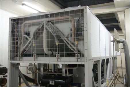
AIR-COOLED SCREW CHILLER

HIGH-EFFICIENCY COMPRESSOR                                                                                                                  UNIT MICROCOMPUTER CONTROL CENTER

                                                                                                                                                  The industrial-level microcomputer controller, together with the LCD
  ●The highly efficient semi-hermetical twin-screw compressor adopts the world-class latest                                                   touch screen, constitutes the control unit of the unit. While TICA’s
  generation 5:6 patented asymmetric tooth-type rotor to greatly improve the adiabatic efficiency.                                            unique self-control technology and up-to-edge control technology in the
                                                                                                                                              world create powerful control functions of our controller.
  This type of high-efficiency motor with large capacity can significantly enhance the energy
                                                                                                                                                The leading intelligent control program ensures accurate management
  efficiency.
                                                                                                                                              of water temperature under any condition and guarantees energy-saving,
  ●The compressor motor directly connects to the rotor with no gearbox involved, which avoids
                                                                                                                                              safe, and stable operation of the unit by automatic control. Meanwhile,
  energy loss caused by gear transmission; moreover, fewer moving parts can ensure lower                                                      the advanced pre-control function enables measures to be taken timely
  noise and a more reliable operation.                                                                                                        before actual failure occurs to avoid frequent shutdown of the unit.
  ●The high-precision filter screen built in the compressor increases the oil separation efficiency up to 99.5%.                                 The unit supports the compiling of weekly operating schedules to
  ●The unit adopts the semi-enclosed twin-screw compressor and air suction cooling motor to ensure that the motor is fully cooled.            implement comprehensive automatic start and stop control of the unit,
  ●The compressor adopts the slide valve for adjustment. A single compressor can precisely match 25% – 100% load changes, and                 which truly implements unattended and automatic operation.
  dual-compressor up to 12.5% – 100% load changes, which reduces operating expenditure to the greatest extent.

LOW-NOISE OPERATION
                                                                                                                                              Main functions:                                                       Protection functions:
                                                                                                                                              Local and remote automatic control                                    Power overvoltage and under-voltage protection
                                                                                                                                              Start and stop control of the unit                                    Protection of power supply default phase, reverse phase, and
                                                                                                                                              Real-time display of the operating status and parameters              unbalanced phase
  ●The unit adopts the low-noise type outer rotor axial flow fan with long type air duct for
                                                                                                                                              Display and settings of control parameters                            Compressor oil level protection
  diversion to effectively reduce the airflow noise. Before delivery, the fan has undergone
                                                                                                                                              Self-test upon unit startup                                           Compressor motor overheat protection
  strict tests for static and dynamic equilibrium to ensure stable and low-noise operation.                                                   Adjustment and control of the energy                                  Compressor motor overload protection
  ●The silencer built in the compressor reduces noise effectively.                                                                            Control of the balanced operation of the compressor                   Compressor overload protection
  ●The compressor uses the precision machined rotor and the surface of the rotor is                                                           Control to prevent frequent startup of the compressor                 Compressor start failure protection
  hardened by laser. The correction of static and dynamic equilibrium can minimize the                                                        Graded energy-saving control of the fan                               Protection of over high condensation pressure (exhaust)
  vibration.                                                                                                                                  Water pump interlock control                                          Protection of over low evaporation pressure (suction)
  ●The compressor feet are equipped with shock pads to reduce unit vibration and substantially lower the unit noise.                          Multi-unit control                                                    Protection of air suction/exhaust pressure difference
                                                                                                                                              Real-time displaying operation permission grading function            System pressure warning protection
                                                                                                                                              Automatic shutdown upon alarm and failure display function            Protection of over low cooling outlet water temperature
                                                                                                                                              Historical fault memory function                                      Water flow switch protection
HIGH-EFFICIENCY HEAT EXCHANGER                                                                                                                RS485 communication interface (communication function)                Protection of over high air exhaust temperature
                                                                                                                                                                                                                    Communication failure protection
                                                                                                                                                                                                                    EVD electronic expansion valve protection

   ●The patented counter-current water-side
   heat exchanger, combined with the
   inner-threaded efficient heat exchange
   pipe, can increase heat exchange                                                                                                         UNIT OPTIONS
   efficiency by 20% to 30%.
   ●The wind-side heat exchanger adopts
   a unique process design to ensure that
   the refrigerant is in the best flow rate in any condition. In this way, the refrigerant pressure in the wind-side heat exchange copper      ●Year-round cooling unit: all-year-round cooling; lowest ambient cooling temperature of -10°C.
   pipe can be reduced to a minimum, which effectively decreases the power consumption of the compressor and improves the                      ●Compressor noise enclosure: to reduce the compressor noise.
   energy efficiency of the unit.
                                                                                                                                               ●Protection screen: to effectively protect the unit.
                                                                                                                                               ●Accessory: spring shock absorber.
   ●The use of inverted “M” type heat exchanger reduces ventilation resistance, improves air flow velocity distribution, and
                                                                                                                                               ●Process cooling unit: to provide customized inlet/outlet water temperature condition.
   increases heat exchange efficiency.
   ●The use of large air volume silent fan increases the air flow through the tube fins, which improves the heat exchange efficiency
   of the wind-side heat exchanger.
   ●The graded control of the unit fan effectively reduces the fan power consumption of the unit in the transitional ambient
   temperature.
   ●The use of new open-window aluminium fin greatly enhances the gas turbulence of the wind-side heat exchange tube and the
   surface of the fin. In this way, the heat exchange efficiency is increased by about 8%.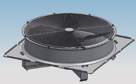
AIR-COOLED SCREW CHILLER
RELIABLE PERFORMANCE SPECIFICATIONS
TASD-BC1 Air-cooled Screw Chiller
●TICA designers conduct optimal design for critical components and system pipelines of the chiller on the basis of existing
Unit Model TASD-BC1 110.1 145.1 180.1 210.1 255.2 290.2 325.2 360.2 390.2 420.2
theories and in combination with internationally advanced design concepts and always put the stability of the chiller in the first
Modular Model - - - - 110+145 145+145 145+180 180+180 180+210 210+210
place.
kW 385 505 642 741 890 1010 1147 1283 1383 1482
●The chiller adopts compressor of international famous brand with high stability. Cooling Capacity
kcal/h 331100 434300 551727 637462 765400 868600 986027 1103454 1189189 1274923
●Original control by electronic expansion valve effectively solves problems of carrying liquid, throwing oil and system oscillation,
Cooling Power Input kW 124 160 201 242 284 319 361 402 443 484
etc. during defrosting and enables stable operation of the chiller.
Cooling Rated Current A 216 278 349 421 493 555 627 699 770 842
●Balanced design of high precision for distribution pipe of refrigerant in heat exchanger on air side of the chiller guarantees
uniform distribution of refrigerant in heat exchanger on air side, enhances heating capacity and improves frosting condition. Maximum Startup Current A 615 683 845 965 1102 1164 1326 1368 1488 1486
●External oil cooler controls oil temperature of compressor and enables more stable and reliable heating operation of the Maximum Operating
A 419 481 523 521 900 962 1004 1046 1044 1042
Current
chiller at low temperature.
Power Supply 380V 3N ~ 50Hz
●Long-term simulation tests: including tests for various variable working conditions, extreme working conditions, defrosting of
Type Highly Efficient Shell-and-tube Exchanger
heat pump and practical tertiary highway transportation, etc. to verify and optimize performance, reliability and structure of the
Cooling
chiller. m3/h 66 87 110 127 153 174 197 221 238 255
Water Flow
Water Inlet/
Water- Outlet Pipe DN 150 150 150 150 150+150 150+150 150+150 150+150 150+150 150+150
side Heat Diameter
Exchanger
Water
Pressure kPa 62 64 58 79 64 64 64 58 79 79
Drop
Water-side
MPa 1.0
Pressure
Type Semi-hermetical Screw Compressor
Energy Regulation
Compressor 25%-100% Four-step Regulation 12.5%-100% Eight-step Regulation
Range
Startup Type Y-Δ
Air Flow m3/h 132000 176000 220000 250000 308000 352000 396000 440000 470000 500000
Fan
Qty Set 6 8 10 10 14 16 18 20 20 20
Type R134a
System Qty 1 2
Refrigerant
Charge
kg 86 100 115 150 186 200 215 230 265 300
Amount
Length mm 3787 4792 5797 5797 9579 10584 11589 12594 12594 12594
PRODUCT NOMENCLATURE Dimensions Width mm 2250
Height mm 2470
Shipping Weight kg 4300 4650 5450 6000 8950 9300 10100 10900 11450 12000
Operating Weight kg 4500 4880 5700 6300 9380 9760 10580 11400 12000 12600
TASD 110 1 B C 1
Refrigerant: 1-R134a Note:
1. Cooling conditions: water inlet/outlet temperature 12/7°C, ambient temperature 35°C;
Series codes: C- cooling only
2. Allowable voltage fluctuation: ±10%;
Design codes: A, B, C… 3. 255RT and later models adopt two modular units, which are transported separately and assembled in parallel on site. The water system pipes of the two units
are connected by the client;
Number of compressors: 1, 2, 3
4. The specifications are subject to change due to product improvement without prior notice.
Specification codes: 110、145…
TASD: TICA air-cooled screw chiller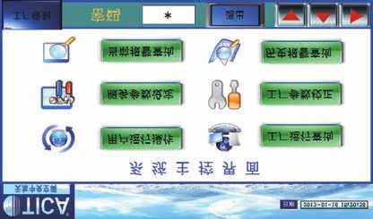
AIR-COOLED SCREW CHILLER
SPECIFICATIONS UNDER VARIABLE OPERATING CONDITION DIAGRAM OF EXTERNAL UNIT DIMENSIONS
Ambient Temperature °C
Water Outlet 15 20 25 30 35 40 45 50
Temperature
Cooling Cooling Cooling Cooling Cooling Cooling TASD110/145/180/210
°C Power Power Power Power Power Power Power Power Power Power
Capacity Capacity Capacity Capacity Capacity Capacity
kW kW kW kW kW kW kW kW kW kW
kW kW kW kW kW kW
5 1.16 0.75 1.11 0.79 1.06 0.83 1.00 0.89 0.94 0.97 0.88 1.05 0.80 1.17 0.74 1.28
7 1.23 0.76 1.18 0.80 1.12 0.86 1.06 0.92 1.00 1.00 0.94 1.08 0.86 1.21 0.79 1.32
8 1.27 0.76 1.22 0.81 1.16 0.87 1.10 0.93 1.03 1.02 0.96 1.10 0.89 1.22 0.82 1.34
10 1.34 0.80 1.29 0.84 1.23 0.89 1.16 0.96 1.09 1.05 1.02 1.14 0.95 1.26 0.87 1.38
12 1.42 0.82 1.36 0.87 1.30 0.92 1.23 1.00 1.16 1.08 1.08 1.17 1.02 1.30 0.93 1.42
15 1.54 0.85 1.48 0.91 1.41 0.97 1.33 1.04 1.25 1.13 1.17 1.24 1.12 1.37 1.02 1.49
UNITS OPERATION CONDITION RANGE
E Outlet D Inlet
TASD-BC1 B
A
Cooling
Shell and Tube Heat Exchanger(Evaporator) Minmum Temperature Maximum Temperature External Unit Dimensions (unit: mm)
Model
Inlet Water Temperature(Starting) — 35°C A B C D E F
Outlet Water Temperature(Operating) 5°C 15°C TASD110.1BC1 3787 2250 2470 2300 369 606
Fin Heat Exchanger (Condenser) Minmum Temperature Maximum Temperature TASD145.1BC1 4792 2250 2470 2300 611 606
Inlet Air Temperature 15°C 50°C TASD180.1BC1 5797 2250 2470 2300 1440 606
Note: TASD210.1BC1 5797 2250 2470 2950 870 606
1. The minimum air inlet temperature of perennial cooling unit: -10°C;
2. If the actual application condition is beyond the above data, please contact with TICA.
TASD255/290/325/360/390/420
WATER PRESSURE DROP DIAGRAM
Main Auxiliary
control control
130 cabinet cabinet
TASD210.1BC1 TASD390.2BC1 TASD420.2BC1
110
Evaporator Pressure Drop (kPa)
TASD145.1BC1 TASD255.2BC1 TASD290.2BC1 TASD325.2BC1 G Outlet F Inlet J Outlet I Inlet B
90 TASD110.1BC1 D E
A
TASD180.1BC1 TASD360.2BC1
External Unit Dimensions (unit: mm)
Model
70 A B C D E F G H I J K
TASD255.2BC1 9579 2250 2470 3787 4792 2300 369 606 2300 611 606
TASD290.2BC1 10584 2250 2470 4792 4792 2300 611 606 2300 611 606
50 TASD325.2BC1 11589 2250 2470 4792 5797 2300 611 606 2300 1440 606
TASD360.2BC1 12594 2250 2470 5797 5797 2300 1440 606 2300 1440 606
TASD390.2BC1 12594 2250 2470 5797 5797 2300 1440 606 2950 870 606
30
TASD420.2BC1 12594 2250 2470 5797 5797 2950 870 606 2950 870 606
40 80 120 160 200 240 280 320
Water Flow (m3/h)
7 8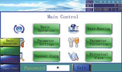
AIR-COOLED SCREW CHILLER
BASE VIBRATION ABSORPTION INSTALLATION DIAGRAM INSTALLATION SKETCH
110 145/180/210
6-Φ14 vibration basorption installation hole 8-Φ14 vibration absorption installation hole
Spring shock absorber
Drainage ditch
B C D B C D E
C15 concrete or that with higher strength grade
255
6-Φ14 vibration absorption installation hole 8-Φ14 vibration absorption installation hole
Main Auxiliary
control control
A
cabinet cabinet
B C D E F G H I
290/325/360/390/420 B C D E F G H
8-Φ14 vibration absorption installation hole 8-Φ14 vibration absorption installation hole
External Unit Dimensions (unit: mm)
Model
A B C D E F G H
TASD110.1BC1 2170 1300 1300
TASD145.1BC1 2170 1200 1200 1200
B C D E F G H I J
TASD180.1BC1 2170 1535 1535 1535
TASD210.1BC1 2170 1535 1535 1535
External Unit Dimensions (unit: mm) TASD255.2BC1 2170 1300 1300 2230 1200 1200 1200
Model
A B C D E F G H I J TASD290.2BC1 2170 1200 1200 1200 2230 1200 1200 1200
TASD110.1BC1 2170 412 1300 1300 TASD325.2BC1 2170 1200 1200 1200 2230 1535 1535 1535
TASD145.1BC1 2170 412 1200 1200 1200 TASD360.2BC1 2170 1535 1535 1535 2230 1535 1535 1535
TASD180.1BC1 2170 412 1535 1535 1535 TASD390.2BC1 2170 1535 1535 1535 2230 1535 1535 1535
TASD210.1BC1 2170 412 1535 1535 1535 TASD420.2BC1 2170 1535 1535 1535 2230 1535 1535 1535
TASD255.2BC1 2170 412 1300 1300 1820 412 1200 1200 1200
TASD290.2BC1 2170 412 1200 1200 1200 1820 412 1200 1200 1200
Note:
1.The gradient of the foundation should be less than 0.1%
TASD325.2BC1 2170 412 1200 1200 1200 1820 412 1535 1535 1535
2.The foundation should be able to support 1.5 times of unit operating weights.
TASD360.2BC1 2170 412 1535 1535 1535 1820 412 1535 1535 1535 3.Sufficient space must be available for drain barrel
TASD390.2BC1 2170 412 1535 1535 1535 1820 412 1535 1535 1535
4.Spring islator must be installed to prevent excessice vibration and noise.
5.Spring islator is optional parts
TASD420.2BC1 2170 412 1535 1535 1535 1820 412 1535 1535 1535
9 10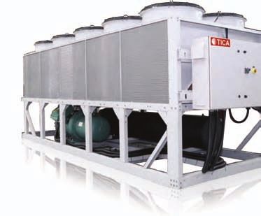
AIR-COOLED SCREW CHILLER
UNIT LIFTING AND PLACEMENT DIAGRAMS ON-SITE WIRING DIAGRAM
TASD unit TASD110/145/180/210
Dedicated cradle
Busbar
EB
Main Input:
Fans circuit controller 80, 81: Remote start & stop
Power
Output:
234, 235: Pump
232, 233: Alarm
connect to busbar EVD GMPR 230, 231: Run
Communication:
330, 331: Remote conmmunication
320, 321: Multi conmmunication
Spring shock absorber
Building surface
Foundation Drainage ditch
Notes: 1. Lift the unit according to the diagram. Make sure to use dedicated lifting equipment, such as cradle, to protect the unit.
2. In case of any scratches occurring during lifting process, please treat the damaged parts. TASD255/290/325/360/390/420
Master
Busbar
EB
UNIT INSTALLATION SPACE DIAGRAMS Fans circuit
Main
controller
Power
Layout requirements for corners or depressions connect to busbar EVD GMPR
Slaver
≤2.2m
Busbar Input:
m
1.5
EB 80, 81: Remote start & stop
≥ Main
controller
Fans circuit
Power Output:
≥2 234, 235: Pump
.5m
232, 233: Alarm
230, 231: Run
EVD GMPR
connect to busbar
Communication:
m ≥2m 330, 331: Remote conmmunication
≥1 320, 321: Multi conmmunication
Notes: 1. The place for installation must be well ventilated. To prevent inverse flow of condenser air, it is recommended to reserve
side spacing as shown above; under such conditions, there should not be any obstacles under the unit;
2. If the unit is blocked by buildings on top, a space height of at least 3 m shall be reserved, ensuring air ventilation of the unit.
3. Since the re-circulating hot air seriously affects the energy efficiency ratio of unit and even causes the condensing pressure
to be too high or the fan motor to get faulty, be sure to reserve the above-mentioned installation space.
11 12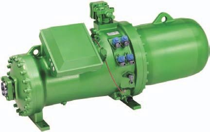
AIR-COOLED SCREW CHILLER

     INSTALLATION AND COMMISSIONING                                                                                                             REQUIREMENTS FOR WATER QUALITY

            The chiller must be installed and maintained by professionals who have been trained, are familiar with local standards and               Since compositions of water quality in different areas are complicated, if the water different from ordinary water is applied,
          rules and have practical operating experiences and qualifications for refrigeration equipment. Initial operation of the chiller            water quality should be inspected before the water enters heat exchanger of the chiller. If water quality is under the
          must be carried out by professional service sectors, otherwise, quality of the chiller cannot be guaranteed.                               requirement for air conditioning water, it should be treated. Relevant water treatment can refer to standard “Design
                                                                                                                                                     Specification for Treatment of Industrial Circulating Cooling Water” or other related standards. The table below can be used
                                                                                                                                                     as reference index.
           Handling of the chiller                   The chiller is loaded and transported integrally. The chiller is filled with refrigerant
                                                     required for normal operation, so special care should be given during loading and
                                                     transportation to avoid damage to the chiller or leakage of refrigerant due to
                                                     reckless operations.

                                                                                                                                                                                                                                     Requirement for air conditioning water
           Acceptance upon                           After arrival of the equipment, carefully check whether all items are complete or
                                                                                                                                                                 Items                                        Unit
                                                     not according to the packing list, and whether components and parts are
           arrival of goods                                                                                                                                                                                                                    Permissive values
                                                     damaged during transportation or not, if damaged, please notify carriers and
                                                     propose claim for compensation in written form. For any damage after the                              Suspended solids                                   mg/L
AIR-COOLED SCREW CHILLER
SCHEMATIC OF EXTERNAL WATER PIPE SELECTION OF WATER SYSTEM PARTS
Single machine
1. Shut-off valve: determined based on water pipe diameter, and in general the valve diameter is selected in
Pressure Water flow consistency with the diameter of pipe connected with the unit.
Thermometer gage switch
End water inlet Energy 2. Water filter: play a role of filtering impurities in water system, and in general over 60-mesh filter is selected.
storage tank
3. Check valve: installed at the outlet of water pump to prevent damage to water pump during backflow of water, the
Shut-off
valve
Shut-off Elastic joint Temperature
sensor
valve diameter is consistent with the diameter of pipe connected with the unit.
valve
Auxiliary electric 4. By-pass valve: installed between inlet and outlet water pipes of the unit container and opened when cleaning pipeline.
heater
5. Thermometer: convenient for overhaul, maintenance and observation of operating conditions of the unit. In general
Heat exchanger
Shut-off on water 0-100℃ is selected.
Expansion valve
water tank 6. Water pump: its water yield is selected according to water flow parameters of the unit.
Pressure Pressure Water Thermometer
Pressure Temperature Water yield of pump=L*1.1 (L-water flow of the unit), the delivery head of water pump is calculated as per the
gage gage pump gage sensor
following formula:
Delivery head of water pump= (water resistance of the unit + the most unfavorable pipe length* (2%~5%) + end
End return Butterfly Water filter Drain Check Butterfly Drain valve Elastic joint
water resistance of the most unfavorable path)*1.1
water valve valve valve valve 7. Automatic vent valve: play a role of discharging the air in water system to enable normal operation of the unit and
installed at the highest point of the unit.
8. Expansion water tank: play a main role of accommodating excessive water, stabilizing water pressure of the
system and replenishing water into the system. In general installed at return water pipe higher than water pipeline
Multi-machine connected in parallel Water flow
switch inside the system to enable normal operation of the unit. It’s volume is calculated as per the following formula:
Volume of expansion water tank V = (0.03~0.034)Vc
Pressure
Vc = system water volume
No.1 heat exchanger
Thermometer gage Shut-off Elastic Temperature
End water inlet Energy
on water side
joint sensor
storage
valve
9. Energy storage water tank: play a role of regulating energy to reduce frequent start/stop of compressor when
tank
Shut-off
Shut-off
Shut-off system load changes, to improve operating efficiency of the system and meanwhile to extend service life of the unit.
valve valve Elastic joint
Auxiliary
valve
Its volume is calculated as per the following formula:
electric heater
Volume of energy storage water tank V (m3) = (Q/27.9n) –Vs
Drain
Expansion
Shut-off
valve
valve
Water flow
switch
Q - refrigerating capacity kW
water tank
Pressure
n - number of heads
No.2 heat exchanger
Pressure Pressure Shut-off
gage gage Water Thermometer gage
valve Elastic Temperature Vs - water volume m3 in pipeline and heat exchanger inside the chilled water system
on water side
pump joint sensor
Shut-off Elastic joint
End return Butterfly Water Drain valve Check Butterfly Drain valve Temperature valve
water valve filter valve valve sensor
Drain valve
Notice
Precautions in design and installation of pipelines: The value of pipeline pressure test should be over 1.25 times the operating pressure, but not be less than 0.6MPa, after
pressure is maintained for 5min, the pressure drop is not more than 0.02MPa, and the system is qualified if no leakage
1. During joint control of modules in combination, hot pump chiller cannot be combined with single cold chiller.
exists upon inspection.
2. Design of water circulating system should be as simple as possible to avoid excessive elbows, and straight pipelines should be
Hydrostatic test should not be carried out when air temperature is lower than 5℃, pressure gage for pressure test is
on the same plane as much as possible.
qualified upon inspection with accuracy not less than 1.5 class, and the full-scale value is 1.5~2 times the maximum
3. Notice the positions of water inlets and outlet of heat exchanger to avoid incorrect connection.
measured pressure.
4. Manual or automatic vent valves should be installed on all peaks of water circulating system.
During pressure test feed water from low part of the system and exhaust air from high part. For pressure test, water should
5. Expansion water tank should be made of anticorrosive and antirust materials and must be installed on the highest point of the
be fed slowly and uniformly, after water reaches the pressure required, stop operation of pump and check the system, and
whole pipeline system.
repair work should not conducted with existence of pressure.
6. Thermometers and pressure gages should be installed at water inlet/outlet.
After qualification by pressure test, wash water pipeline over and over (notice not to pass equipment) to be qualified until
7. For double-head chillers, temperature sensing blind tubes should be reserved by the user on water main for installation of
drainage does not carry impurities such as silt and scrap iron, etc. and is not turbid.
temperature sensor.
8. On the bottom of all local elbows, drain valves should be installed so as to evacuate water in the whole system.
9. Shut-off valves are installed on water pipeline for connection of heat exchanger of the chiller with water pipes of the user.
10. Bypass valves are installed between inlet and outlet water pipelines of heat exchanger of the chiller with convenience for
overhaul and flush of pipelines.
11. Install elastic joints to reduce vibration of pipelines.
12. Impurities in water system will cause scaling of heat exchanger, so filter should be installed before water pump.
13. In order to improve refrigerating (heating) effect and save energy, pipelines should be strictly kept warm.
14. In order to prevent frequent tripping of the chiller due to too small load during operation, the user is recommended installing
energy storage tank.
15 16AIR-COOLED SCREW CHILLER
DATE NOTE DATE NOTE
17 18You can also read


