Nitrogen Generator System Manual
←
→
Page content transcription
If your browser does not render page correctly, please read the page content below
INSTRUCTION MANUAL

                                 2ND GENERATION

         Nitrogen Generator System Manual
N2-GEN-MANUAL 3.8   READ AND UNDERSTAND THIS MANUAL PRIOR TO OPERATING OR SERVICING THIS PRODUCT.

                                     Patented 2nd Generation Nitrogen Generator Systems are manufactured and distributed by
                                              Waukesha® Service & Components, a division of SPX Transformer Solutions, Inc.
                                                 U.S. Patent Nos. 6,581,694; 6,568,287; 6,062,821; 5,902,381 and 5,744,764.
2nd GENERATION NITROGEN GENERATOR SYSTEM MANUAL

TABLE OF CONTENTS

General Description & Principle of Operation                                                              Page 2
Nitrogen Membrane Principle of Operation                                                                  Page 3
Safety Information                                                                                        Page 4
Specifications                                                                                            Page 5
Single Transformer Installation                                                                           Page 6
Multiple Transformer Installation                                                                         Pages 7–8
Electrical Connections                                                                                    Page 9
General Component Identification                                                                          Pages 10–11
Start-up Instructions                                                                                     Pages 12–14
Climate Control Description & Operation                                                                   Pages 15–17
System Alarms                                                                                             Page 18
System Shut Down Procedure                                                                                Page 19
Periodic Maintenance                                                                                      Pages 20–21
Troubleshooting                                                                                           Page 22
Compressor Conservator Circuit                                                                            Page 23

                                                                                                         N2-Gen-Manual REV 3.8, 8/2014
                                                                                               ®
Patented 2nd Generation Nitrogen Generator Systems are manufactured and distributed by Waukesha Service & Components, a division of
SPX Transformer Solutions, Inc. U.S. Patent Nos. 6,581,694; 6,568,287; 6,062,821; 5,902,381 and 5,744,764.
                                                                                                                                         1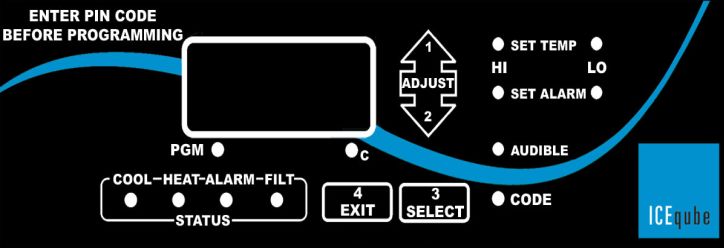
2nd GENERATION NITROGEN GENERATOR SYSTEM MANUAL

GENERAL DESCRIPTION
The N2 Nitrogen Generator is designed for use on tap changers, breakers, main tanks or any other
electrical device requiring a gas-blanketed enclosure. The unit produces nitrogen by separating oxygen from
compressed air by means of hollow fiberglass separation membranes. The compressed air is supplied by an
on-board compressor and the generated nitrogen (N2) is fed to internal storage vessels. The output
concentration of the air separator (nitrogen purity) is factory pre-set. The final regulator system maintains
the gas-blanketed tank pressure between 0.5 and 5.0 psi at all times. If the tank pressure reaches a
minimum of 0.5 psi, nitrogen is sent from the storage vessels through the regulator assembly to the tank.
Should tank pressure rise above 5.5 psi, a relief valve will open to bleed off excess pressure to atmosphere.
IMPORTANT: Changing the output concentration may only be performed by trained and authorized
service technicians.
SYSTEM PRINCIPLE OF OPERATION
Refer to figure 1 below. The nitrogen generator system is contained within a climate-controlled cabinet that
closely regulates the temperature range within which the compressor system and nitrogen membrane are
required to operate. When the on-board nitrogen storage tank drains to a preset level (100 psi), a
compressor run cycle is initiated to refill the storage tank. Cool filtered air is drawn into the compressor and
compressed to a nominal output of 150 psi. The hot compressed air is then directed through a heat
exchanger that cools the compressed air below dew point for easier moisture removal. As the hot air travels
through the coalescing filter, the condensed moisture collects in the filter bowl for draining at the end of the
compressor cycle. The final filter removes all particulates in the compressed air stream before entering into
the membrane assembly. As the air travels through the membrane, the outgoing nitrogen is regulated to a
specific flow rate and pressure that defines nitrogen purity at the given membrane operating temperature.
The output nitrogen of the membrane is diverted to atmosphere for a preset time, ensuring all contaminate
gases are purged before diverting to the storage tank. The generator storage tank stores 3 gallons of
nitrogen at 100–120 psi to supply the final regulator system controlling the external gas space.

                                       INLET AIR                    FILTER                   FLOW
                                        FILTER                    WITH PURGE               REGULATOR

                                      COMPRESSOR                  NITROGEN                  ONE WAY
                                       (2 STAGE)                  MEMBRANE                   VALVE

                                                             02                02

                                         HEAT                      TIMER                     STORAGE
                                      EXCHANGER                   SOLENOID                    TANK

                                      COELESCING                    FLOW                      FINAL
                                      PRE FILTER                  REGULATOR                 REGULATOR
                                      WITH PURGE                                             SYSTEM

                                                             N2                02

                                     Figure 1 – Nitrogen Generator Module Functional Operation

                                                                                                         N2-Gen-Manual REV 3.8, 8/2014
                                                                                               ®
Patented 2nd Generation Nitrogen Generator Systems are manufactured and distributed by Waukesha Service & Components, a division of
SPX Transformer Solutions, Inc. U.S. Patent Nos. 6,581,694; 6,568,287; 6,062,821; 5,902,381 and 5,744,764.
                                                                                                                                         2
2nd GENERATION NITROGEN GENERATOR SYSTEM MANUAL

NITROGEN MEMBRANE PRINCIPLE OF OPERATION
Refer to Figure 2 below. Compressed air flows into the hollow fiber membrane. Various air components,
such as oxygen, nitrogen, carbon dioxide and water vapor pass through the membrane wall, but the rate at
which this occurs differs for the various gases. Oxygen and water vapor have a high diffusion rate and
diffuse rapidly through the membrane wall. Nitrogen has a low diffusion rate and penetrates the membrane
wall slowly, mainly at the end of the hollow fibers. The purity of the nitrogen at the end of the fibers depends
on the velocity of the gas flow. The nitrogen capacity of the membrane depends on the flow rate, operating
temperature and operating pressure of the compressor.

                                                    Figure 2 – Membrane and Gas Flow

                                                                                                         N2-Gen-Manual REV 3.8, 8/2014
                                                                                               ®
Patented 2nd Generation Nitrogen Generator Systems are manufactured and distributed by Waukesha Service & Components, a division of
SPX Transformer Solutions, Inc. U.S. Patent Nos. 6,581,694; 6,568,287; 6,062,821; 5,902,381 and 5,744,764.
                                                                                                                                         3
2nd GENERATION NITROGEN GENERATOR SYSTEM MANUAL
SAFETY INFORMATION
Proper use of this equipment is important for your personal safety and for trouble-free functioning of the unit.
Incorrect control or attempts to perform adjustments could cause damage or lead to incorrect gas supply. Be
sure to read and understand all instructions before attempting to operate the unit. The unit is designed to
produce nitrogen. The nitrogen is supplied by an internal generator that produces nitrogen from ambient air
through a process of separating oxygen from normal air. You must not use the unit for any other purpose
than what is specified. Do not operate the unit beyond its limits (see Specifications table on page 5). In
addition to the warnings and cautions in this manual, use the following safety guidelines for safe operation
of the unit:
WARNING: This unit is an electrical appliance. Make sure that the main power supply is
disconnected before you perform installation, maintenance or repair work.
WARNING: If you must work on the equipment with the main power supply on, be aware of
electrical hazards.
DANGER: When working on the equipment, do not wear loose clothes, jewelry or hair. They
could become entangled in the fan blades.
WARNING: The compressor becomes very hot when operating. Be careful when you open
the cabinet after the unit has been operating for any length of time. Do not touch the
compressor. Allow it to cool down before you start to perform any service on the unit. If you
must work on the unit while it is hot, be sure to wear protective gloves to protect yourself
from the heat.
CAUTION: Do not block the ventilation inlets and outlets as this could cause overheating
and damage to the unit.
CAUTION: Do not allow the AC unit to be positioned other than vertical. If the AC is
positioned horizontally, reposition to a vertical position for 12 hours before starting unit.
WARNING: In order to prevent injury or damage caused by the sudden release of
compressed air, make sure that the unit and connected systems are fully depressurized
before you start uncoupling parts of the system. Make sure no one tampers with the
pressure-relief valve.
DANGER: This unit produces nitrogen and oxygen-enriched air. Nitrogen can cause
suffocation. Oxygen-enriched air can lead to increased risk of fire in the event of contact
with flammable products. Ensure adequate ventilation at all times.
IMPORTANT The following words and symbols appear throughout this manual and designate important
safety instructions:
DANGER: Indicates information important to the proper operation of the equipment. Failure
to observe will result in damage to the equipment and/or severe bodily injury or death.
WARNING: Indicates information important to the proper operation of the equipment. Failure
to observe may result in damage to the equipment and/or severe bodily injury or death.
CAUTION: Indicates information important to the proper operation of the equipment. Failure
to observe may result in damage to the equipment.
Read all safety instructions to avoid personal injury or death and to avoid damage to the unit or property.
N2-Gen-Manual REV 3.8, 8/2014
®
Patented 2nd Generation Nitrogen Generator Systems are manufactured and distributed by Waukesha Service & Components, a division of
SPX Transformer Solutions, Inc. U.S. Patent Nos. 6,581,694; 6,568,287; 6,062,821; 5,902,381 and 5,744,764.
42nd GENERATION NITROGEN GENERATOR SYSTEM MANUAL
SPECIFICATIONS
NOMINAL PERFORMANCE ELECTRICAL
Nitrogen (N2 )* 125 psi Voltage/Frequency 120V AC, 60 Hz
1–19A
Purity of N2 Delivered* 99.5% Power Consumption* depending on ambient
conditions
Flow rate* ~3.0 SLPM Potential Free Alarm Normally open,1A
Dew Point of N2
99.0% Air Quality
ambient air
Dew Point of N2
–40°C Relative Humidity < 90%
Delivered
1.0 SLPM
Flow Rate Continuous Altitude 0–6000 ft.
5.0 SLPM Purge
Maximum Oil Volume to
30,000 gallons ENVIRONMENT
Blanket
FINAL OUTPUT PRESSURE Noise Level Less than 65 dB(A)
Regulator Output Between 0 and 2.0 psi
Location Outdoors, wall mounted
Control Range Between 0.2 and 5.5 psi
* Nitrogen Delivery properties at nominal temperature Safety Standards CE; applicable standards
of 25°C.
* Typical operation:
IMPORTANT: A 30 amp breaker located at the Fan only — 1A
Heaters (low ambient) — 10A
main power supply to the system is AC (high ambient) — 5A
recommended for protection of the N2 Generator. Compressor Run (5 min) — 9A
Table 1 – Nitrogen Generator Specifications
CAUTION: The nitrogen generator is designed to provide the equivalent volume of nitrogen as a
standard nitrogen system consuming the standard 225 ft3 bottle every 4 days or more. Operating
the equipment beyond the rated 1 l/m continuous will result in damage to the unit and void the
manufacturer’s warranty, i.e. multiple transformer application or leaking transformer with a
consumption of greater than 1 l/m. The internal compressor is rated to operate in a maximum
ambient temperature of 104°F. To ensure maximum service life, a conservator circuit has been
implemented to protect the N2 Generator and internal compressor.
If the application requires more nitrogen volume, consult the factory for a specialized unit.
N2-Gen-Manual REV 3.8, 8/2014
®
Patented 2nd Generation Nitrogen Generator Systems are manufactured and distributed by Waukesha Service & Components, a division of
SPX Transformer Solutions, Inc. U.S. Patent Nos. 6,581,694; 6,568,287; 6,062,821; 5,902,381 and 5,744,764.
52nd GENERATION NITROGEN GENERATOR SYSTEM MANUAL
INSTALLATION – SINGLE TRANSFORMER
CAUTION: The unit must be mounted in an upright position. Do not mount unit on its side or
back. The unit MUST be vertical for 12 hours before turning the unit on.
WARNING: A crane, or similar lifting device, is required to lift and secure unit to wall
mounting surface.
CAUTION: Do not block the ventilation inlets and outlets as this could cause overheating
and damage to the unit.
WARNING: Support structure and mounting hardware must be capable of supporting the
generator weight of 380 lbs. minimum. Cabinet is designed to be mounted using 1/2”
hardware.
The unit must be mounted above grade level.
Install unit away from heat sources.
Do not install in an enclosed cabinet; proper ventilation is required.
Figure 3 – Generator Mounting Dimensions: Standard Generator (left) and Generator with Bottle Back-Up (right)
1) Measure and mark the mounting holes or studs as shown by the center-to-center distances of Figure 3
above. IMPORTANT: Verify the bolt holes are level and high enough to support cabinet above grade.
2) Lift the unit into position with crane and top hook.
3) Secure hardware. NOTE: Cabinet is designed to be installed using 1/2” hardware.
4) Plumb to transformer using copper or stainless steel 1/4” or larger tubing. NOTE: Inlet and outlet ports
of generator are female 1/4” NPT.
N2-Gen-Manual REV 3.8, 8/2014
®
Patented 2nd Generation Nitrogen Generator Systems are manufactured and distributed by Waukesha Service & Components, a division of
SPX Transformer Solutions, Inc. U.S. Patent Nos. 6,581,694; 6,568,287; 6,062,821; 5,902,381 and 5,744,764.
62nd GENERATION NITROGEN GENERATOR SYSTEM MANUAL
INSTALLATION – MULTIPLE TRANSFORMERS
CAUTION: The unit must be mounted in an upright position. Do not mount unit on its side or
back. The unit MUST be vertical for 12 hours before turning the unit on.
WARNING: A crane or similar lifting device is required to lift and secure unit to wall
mounting surface.
CAUTION: Do not block the ventilation inlets and outlets as this could cause overheating
and damage to the unit.
WARNING: Support structure and mounting hardware must be capable of supporting the
generator weight of 380 lbs. minimum. Cabinet is designed to be mounted using 1/2”
hardware.
WARNING: Use of the Nitrogen Generator for multiple transformers requires evaluation of
several conditions to maintain the health of each transformer. Do not proceed unless all
conditions are met.
1) Calculate the required usage for each transformer to be connected to the generator. The total sum of
usage cannot exceed 1 slpm. For example, 1 slpm continuous usage equates to using a single standard
225 cuft nitrogen bottle every 4 days.
2) IMPORTANT: Each transformer must have a final nitrogen pressure regulation system with tank alarms.
3) IMPORTANT: Piping for each transformer must contain a one-way valve to prevent airspace backflow
to the supply line.
4) IMPORTANT: Piping for each transformer must contain a separate isolation valve.
5) IMPORTANT: Each transformer must be protected by an appropriate pressure/vacuum device.
Figure 4 – Multiple Transformer Installation Flow
N2-Gen-Manual REV 3.8, 8/2014
®
Patented 2nd Generation Nitrogen Generator Systems are manufactured and distributed by Waukesha Service & Components, a division of
SPX Transformer Solutions, Inc. U.S. Patent Nos. 6,581,694; 6,568,287; 6,062,821; 5,902,381 and 5,744,764.
72nd GENERATION NITROGEN GENERATOR SYSTEM MANUAL
Use one or more
N2 Generators For each transformer,
for N2 supply use SPX Waukesha
Part Number MN2-0A0133
7.5 psi
TO TRANSFORMER
Regulator
Bypass
Valve set
to “Bypass”
TO TRANSFORMER
TROUBLESHOOTING
THE FAN OR HEATER IS NOT OPERATING
Confirm that the voltage input to the PTC2 assembly is the correct voltage. Check heater assembly
terminals at the power harness quick-connect plug.
Check wiring harness for cuts or bare insulation.
Confirm fan assembly has not been clogged with debris—clean if necessary. TO TRANSFORMER
Nitrogen Generator Mini N2 Shown.
Standard Nitrogen Standard N2 System can be
with Bottle Back-Up
Generator Shown used with addition of one-way
Shown
and isolation valves.
Figure 5 – Typical Example of Multiple Transformer Installation
N2-Gen-Manual REV 3.8, 8/2014
®
Patented 2nd Generation Nitrogen Generator Systems are manufactured and distributed by Waukesha Service & Components, a division of
SPX Transformer Solutions, Inc. U.S. Patent Nos. 6,581,694; 6,568,287; 6,062,821; 5,902,381 and 5,744,764.
82nd GENERATION NITROGEN GENERATOR SYSTEM MANUAL
ELECTRICAL CONNECTIONS
WARNING: Electrical shock hazard. Failure to follow these instructions could result in
serious injury or death.
Electrical ground is required on this piece of equipment.
Do not use an extension cord with this piece of equipment.
The unit should be grounded according to local electrical codes to prevent the possibility of electrical
shock. It requires a grounded receptacle with separate electrical lines, protected by fuses or circuit
breaker of the proper rating.
Check with a qualified electrician if you are in doubt as to whether the equipment is properly grounded.
Figure 6 – Alarm and Power Connections for All N2 Generators (left) and Additional Changeover Auxiliary Alarm for
Bottle Back-Up Systems (right)
1) Conduit entry points are located on both sides of the cabinet. Install conduit with sealed connectors to
prevent water entry to the generator system.
2) After pulling wire, seal conduit entry with expanding foam (or similar). The generator compressor must
not be allowed to draw air from conduit.
3) Locate the terminal block on the regulator module. Loosen the two thumb screws and swing terminal
panel cover out of the way to expose terminal connections.
4) Connect the wiring to the terminals as shown in Figure 6 above.
5) Alarm connections are not required for generator operation but are highly recommended.
6) Reposition the terminal panel cover and tighten thumb screws.
N2-Gen-Manual REV 3.8, 8/2014
®
Patented 2nd Generation Nitrogen Generator Systems are manufactured and distributed by Waukesha Service & Components, a division of
SPX Transformer Solutions, Inc. U.S. Patent Nos. 6,581,694; 6,568,287; 6,062,821; 5,902,381 and 5,744,764.
92nd GENERATION NITROGEN GENERATOR SYSTEM MANUAL
Climate Nitrogen
Control Regulator
Interface Module
Nitrogen
Climate
Generator
Control
Module
Module
Climate
Control
Filter
Heat Exchanger
Cabinet Assembly
Air Inlet
Filter
Nitrogen Membrane
Assembly
Oil Sump
rd Particle Filter
Regulator Module 3
Stage Regulation Storage Tank Pressure
Bypass Valve Switch Assembly
Coalescing Filter Nitrogen Purge Solenoid and
Assembly Membrane Pressure Gauge
Nitrogen Storage Tank
Air Compressor
Air Compressor
Filter
Enclosure Heater
(1 of 3)
Figure 7 – Standard Nitrogen System Component Identification
N2-Gen-Manual REV 3.8, 8/2014
®
Patented 2nd Generation Nitrogen Generator Systems are manufactured and distributed by Waukesha Service & Components, a division of
SPX Transformer Solutions, Inc. U.S. Patent Nos. 6,581,694; 6,568,287; 6,062,821; 5,902,381 and 5,744,764.
102nd GENERATION NITROGEN GENERATOR SYSTEM MANUAL
Nitrogen
Automatic
Changeover
Module
Climate
Nitrogen
Control
Regulator
Interface
Module
Climate Nitrogen
Control Generator
Module Module
Climate
Control
Filter
One-Way NOTE: This regulator must be set to 65 psi 3000-to-65 psi
Shunt Trip Valves for proper system operation. Bottle
Breaker Regulator
Shunt Trip
160 psi
Aux Switch
Output
Gauge
Outlet to 75 psi
N2 Bottle Inlet
Regulator Module Pressure
Switch
Generator Inlet
Figure 8 – Bottle Back-Up Nitrogen System Component Identification with Automatic Changeover Module Sub-Components
N2-Gen-Manual REV 3.8, 8/2014
®
Patented 2nd Generation Nitrogen Generator Systems are manufactured and distributed by Waukesha Service & Components, a division of
SPX Transformer Solutions, Inc. U.S. Patent Nos. 6,581,694; 6,568,287; 6,062,821; 5,902,381 and 5,744,764.
112nd GENERATION NITROGEN GENERATOR SYSTEM MANUAL
START-UP
IMPORTANT: Make sure the unit has been properly installed according to the Installation
Instructions included in this manual. The unit MUST be vertical for 12 hours before turning the
unit on.
CAUTION: When the compressor starts, the cooling fan on the heat exchanger should rotate.
If fan is not rotating, turn unit off or damage to the unit could occur.
The generator system is factory set for optimum purity and no adjustments are necessary. The design of the
system is such that the operating temperatures of all components must be controlled to optimize nitrogen
purity. Because of this, it is necessary for the climate control system be energized for a period of 8 hours
prior to releasing nitrogen from the generation system.
The climate control system is preset to cool when the enclosure air temperatures exceed 80°F and heat
when the enclosure air temperature falls below 63°F. The enclosure air is continually cycled through the
system to avoid temperature gradients anywhere in the system.
After all components have been brought within temperature specifications, the generator is ready for use
and the gas space purge operation can begin.
From Gas
Space
To Gas
Space
Gas Space Gas Space
Pressure Return Valve
Gauge and (Open During
Generator Outlet Alarm Point Purge Operation
Valve (Shown in Settings ONLY)
Open Position)
Figure 9 – Generator Inlet and Outlet Valves
1) Remove “Ship Block” under the compressor (the block provides stability during shipping).
2) Before operating, gas space pressure switch contacts must be set to allow the needle to move (alarm
points protect the needle during transport).
3) Loosen clamp around the needle alarm knobs. A small screw is located on the bottom of the clamp.
4) Adjust the low pressure contact (left knob) to 0.2 psi. Adjust the high pressure contact (right knob) to
5.5 psi.
5) Tighten the clamp.
6) Turn on the main power feed to the generator with appropriate fuse or breaker disconnect.
N2-Gen-Manual REV 3.8, 8/2014
®
Patented 2nd Generation Nitrogen Generator Systems are manufactured and distributed by Waukesha Service & Components, a division of
SPX Transformer Solutions, Inc. U.S. Patent Nos. 6,581,694; 6,568,287; 6,062,821; 5,902,381 and 5,744,764.
122nd GENERATION NITROGEN GENERATOR SYSTEM MANUAL
START-UP (continued)
7) Verify that the climate control internal fan is operating and climate control interface is energized.
8) Verify storage tank pressure. If tank is empty or below 100 psi, the air compressor should immediately
start and run for approximately 5–7 minutes. NOTE: A strong hissing sound will be heard for the first
2–3 minutes as the nitrogen is diverted to atmosphere before being brought to full purity.
9) Close generator door and wait for enclosure temperature to be brought within specifications.
10) After compressor charges the storage tank and shuts off, perform a continuity check on the following
alarms contacts:
a) Terminals 1 to 2 – OPEN Terminals 2 to 3 – OPEN
b) Terminals 4 to 5 – OPEN Terminals 5 to 6 – CLOSED
c) Terminals 11 to 12 – OPEN
11) Open the outlet valve. Compressor will cycle as storage tank drains to 100 psi. Compressor shut-off is
110–125 psi. Typical runtime is 5–10 minutes, depending upon altitude.
12) Rotate the regulator panel bypass valve from full regulation to bypass operation.
13) Open the return valve.
14) Close the generator door and latch.
15) Purge for the calculated amount of time based upon 5 liters per minute flow rate.
16) Close return valve.
17) Change regulator panel bypass valve from bypass mode to full regulation mode. This will maintain the
gas space from 0.5 psi to 5 psi.
IMPORTANT: Check all pipes and connections for leaks using soap or leak-tracing spray. Any
leakage will reduce capacity considerably.
PROPER SYSTEM OPERATION CHECKS
1) During air compressor run and with outlet valve shut, check membrane outlet gauge (on top of storage
tank) and verify that the pressure rises above 130 psi. If not, leaks exist between the compressor and
storage tanks or the inlet carbon filter and compressor filter may be clogged.
2) Verify that compressor turns on at 90–100 psi and turns off at 110–125 psi. If not, readjust.
NOTE: In higher altitude locations, the pressures may need to be adjusted to the low side of
specifications.
3) Verify that the nitrogen storage system is not leaking. With generator outlet valve shut and the air
compressor off, verify that no decrease in pressure takes place on the nitrogen regulator module gauge.
If a decrease is present, the one-way valve, storage tank or nitrogen regulator module may be leaking.
4) Verify during compressor run that the coalescing filter purges the collected water and reseals during the
next compressor run. The oil sump drain can be used to speed the cycling of the air compressor.
5) At each compressor start, verify that the solenoid valve diverts to atmosphere. At each start, a strong
hissing sound will occur for two minutes. If not, the solenoid valve may have failed. If the hissing sound
is heard for less than or longer than two minutes, the solenoid timer is misadjusted. Push the
corresponding buttons on timer to display 110 (seconds).
N2-Gen-Manual REV 3.8, 8/2014
®
Patented 2nd Generation Nitrogen Generator Systems are manufactured and distributed by Waukesha Service & Components, a division of
SPX Transformer Solutions, Inc. U.S. Patent Nos. 6,581,694; 6,568,287; 6,062,821; 5,902,381 and 5,744,764.
132nd GENERATION NITROGEN GENERATOR SYSTEM MANUAL
START-UP: Bottle Back-Up Systems Only
1) Install the nitrogen bottle into the cabinet and install the supplied pigtail.
2) Place the shunt bypass switch in the OFF position.
3) Place the circuit breaker in the ON position.
4) Perform the start-up and operation checks described in the previous section.
5) Place the shunt bypass switch in the ON position
6) Open bottle and verify that the bottle gauge is above 200 psi.
TO VALIDATE THAT BOTTLE BYPASS IS WORKING CORRECTLY:
1) Turn the circuit breaker to the OFF position.
2) Open the oil sump drain to bleed nitrogen from generator storage tank.
3) At 75 psi (+/– 2 psi) decreasing, the automatic changeover pressure switch contacts should change
state. This would normally send a shunt trip signal to the circuit breaker.
4) At 65 psi (+/– 5 psi) decreasing, the automatic changeover bottle regulator should begin flowing
nitrogen and the regulator module pressure gauge should hold steady at 65 (+/– 5 psi).
5) If bottle regulator pressure is incorrect, adjust automatic changeover panel pressure regulator by
turning knob.
6) After verification is complete, close oil sump drain and turn shunt bypass switch and circuit breaker to
the ON position. Verify that the circuit breaker immediately trips. Circuit breaker should trip at any
pressure below 75 psi.
7) Turn shunt bypass switch to the OFF position and turn circuit breaker to the ON position.
8) Generator will fill to maximum storage pressure.
9) Turn shunt bypass switch to the ON position.
N2-Gen-Manual REV 3.8, 8/2014
®
Patented 2nd Generation Nitrogen Generator Systems are manufactured and distributed by Waukesha Service & Components, a division of
SPX Transformer Solutions, Inc. U.S. Patent Nos. 6,581,694; 6,568,287; 6,062,821; 5,902,381 and 5,744,764.
142nd GENERATION NITROGEN GENERATOR SYSTEM MANUAL
CLIMATE CONTROL
As soon as electrical power is supplied to the Generator system, the cool air stream blower will start to
operate. The blower will run continuously so that the controller can monitor the enclosure’s internal
temperature. The enclosure temperature will be displayed on the face of the controller.
If the enclosure temperature is greater than the factory cooling set point of 80°F, the “Cool” status LED will
flash. This indicates that the coolant compressor’s automatic off cycle timer is working. The off cycle timer is
factory set at 3-1/2 minutes. At the end of 3-1/2 minutes, the coolant compressor and the condenser air
blower will begin to operate. This signifies that the cooling system has begun operation to remove heat and
humidity from the enclosure. This procedure may take 20 to 30 minutes before it reaches full capacity.
When the temperature inside the enclosure decreases 7°F below the “Cooling on” set point, the coolant
compressor and the condenser blower will cycle off. The cool air blower will continue to operate, circulating
air within the enclosure. The controller has a factory programmed temperature differential of 7°F.
Example: “Cooling on” @ 80°F; “Cooling off” @ 73°F.
The climate control system also provides power to three external heaters which are mounted in various
places within the equipment enclosure. If the enclosure temperature is below the factory heating set point of
63ºF, the heat status LED will be ‘”on”. This indicates the heat relay has been energized and is providing
power to the three 400 watt heaters (no time delay exists before heating begins). When the temperature of
the enclosure rises 7°F above the set point, the controller will de-energize the heat relay and cycle the
heater “off”.
NOTE: There is a deadband programmed into the controller that prevents heating and cooling from
operating simultaneously.
PROGRAMMING THE CONTROLLER
The controller has been programmed at the factory
with typical default settings for immediate system
operation. Please review the following default settings:
1) Cooling system on temperature 80° F
2) Heating system on temperature 63° F
3) High enclosure temperature alarm 105° F
4) Low enclosure temperature alarm 40° F Figure 10 – Climate Control Interface
5) Audible and Visual alarm “ON”
6) Digital display in degrees Fahrenheit
7) Filter maintenance alarm 0 days – Disabled
8) High condenser temperature alarm 170° F
N2-Gen-Manual REV 3.8, 8/2014
®
Patented 2nd Generation Nitrogen Generator Systems are manufactured and distributed by Waukesha Service & Components, a division of
SPX Transformer Solutions, Inc. U.S. Patent Nos. 6,581,694; 6,568,287; 6,062,821; 5,902,381 and 5,744,764.
152nd GENERATION NITROGEN GENERATOR SYSTEM MANUAL
CLIMATE CONTROL (continued)
The temperature alarm settings have been preset to protect the generator system before known failure
values. Changing these values is generally not recommended; however, if the above factory values have
been inadvertently changed, the following programming information is provided for reference.
To change the factory default settings, enter the programming code sequence:
“1 Adjust-up” arrow
“2 Adjust-down” arrow
“3 Select”
“4 Exit”
After pressing the above sequence, the program LED should illuminate along with three alternating flashing
boxes on the display face, indicating the code was accepted. If no selection is made within one minute, the
system returns to the normal operating mode.
NOTE: Pressing the “4 Exit” button at any time while in the programming mode returns the
controller to the normal operating mode.
Press the “3 Select” button to continue programming. The set temperature “HI” LED illuminates with the
display indicating the ‘cooling on’ set point. The coolant compressor will begin operation at this temperature
and will remain operating until the enclosure temperature decreases approximately seven degrees
Fahrenheit (four degrees Celsius). Press the “1 Adjust-up” or “2 Adjust-down” arrow until the desired set
point is displayed. The range for this adjustment is 70°F to 126°F, (21°C to 52°C). When the adjustment is
complete, press the “3 Select” button to continue.
The set temperature “LO” LED is on with the display indicating the ‘heating on’ set point. The heating
system will begin operation at this temperature and remain operating until the enclosure temperature
increases approximately seven degrees Fahrenheit (four degrees Celsius). Press the “1 Adjust-up” or “2
Adjust-down” arrow until the desired set point is displayed within a range of 0°F to 63°F (–17.8°C to
+17°C).
NOTE: Review alarm settings if the ‘cool on’ or ‘heat on’ set points have been changed.
Press the “3 Select” button to continue. The set alarm “HI” LED is on with the display indicating the high
temperature alarm set point. The alarm will activate at this temperature and will automatically reset at two
degrees Fahrenheit (one degree Celsius) below this temperature. Press the “1 Adjust-up” or “2 Adjust-
down” arrow to change the alarm set point to a point greater than 8ºF (or 4ºC) above the set temperature
“HI” set point, to 135°F (or 57°C).
Press the “3 Select” button to continue. The set alarm “LO” LED is on with the display indicating the low
temperature alarm set point. The alarm will activate at this temperature and will automatically reset at two
degrees Fahrenheit (or one degree Celsius) above this temperature. Press the “1 Adjust-up” or “2 Adjust-
down” arrow to change the alarm set point to a point no less than 8º F (4ºC) below the set temperature
“LO” set point to –20°F (or –29°C).
N2-Gen-Manual REV 3.8, 8/2014
®
Patented 2nd Generation Nitrogen Generator Systems are manufactured and distributed by Waukesha Service & Components, a division of
SPX Transformer Solutions, Inc. U.S. Patent Nos. 6,581,694; 6,568,287; 6,062,821; 5,902,381 and 5,744,764.
162nd GENERATION NITROGEN GENERATOR SYSTEM MANUAL
CLIMATE CONTROL (continued)
Press the “3 Select” button to continue. The alarm LED will flash and the display will show “ALL”, indicating
the “ALL” alarm on/off status. Press “3 Select” and the display will show either “ON” or “OFF”, indicating
current alarm status. Press “1 Adjust-up” or “2 Adjust-down” to toggle the mode as desired. If the “OFF”
mode is selected, no alarms will activate and the audible on/off select function is skipped.
Press the “3 Select” button to continue. The audible LED will flash and the display will show “AUD”,
indicating the audible alarm on/off status. Press “3 Select” and the display shows “ON” or “OFF” indicating
the current audible alarm status. Press “1 Adjust-up” or “2 Adjust-down” arrow to toggle the mode
desired.
Press the “3 Select” button to continue. The “C” LED flashes and the display shows either “F” for degrees
Fahrenheit or “C” for degrees Celsius. Press the “1 Adjust-up” arrow or “2 Adjust-down” arrow to toggle
the mode as desired.
Press the “3 Select” button to continue. The code LED is on and the display shows “PIN”. To set a new
user PIN code, press the “1 Adjust-up” button. The display will flash “4”, prompting an entry of a four button
sequence using the “1 Adjust-up”, “2 Adjust-down”, “3 Select” and/or “4 Exit” buttons. Any sequence
of the four buttons may be programmed as the code. As the buttons are pressed, the display will show the
number of buttons that were pressed.
NOTE: After pressing a button, there will only be 5 seconds to press the next button. If the next button is not
pressed within the allotted time, the system will default to no PIN code, indicated by “0” on the display. Once
the sequence is entered the display will no longer flash, and will show “4”.
CAUTION Always record the selection sequence (PIN code) and store in a secure place.
Press the “3 Select” button to continue. The filter LED flashes and the display will show “FIL”, indicating the
filter alarm DAYS selection. Press the “3 Select” button and the display will show the number of days that
the alarm is set in one-half day increments. Example: 10.5 indicates the alarm will activate every ten and
one-half days.
Press the “1 Adjust-up” or the “2 Adjust-down” arrow to vary the desired number of days. Programming 0
days will disable the alarm.
NOTE: The required number of days to set this alarm will be determined by the ambient air
conditions.
N2-Gen-Manual REV 3.8, 8/2014
®
Patented 2nd Generation Nitrogen Generator Systems are manufactured and distributed by Waukesha Service & Components, a division of
SPX Transformer Solutions, Inc. U.S. Patent Nos. 6,581,694; 6,568,287; 6,062,821; 5,902,381 and 5,744,764.
172nd GENERATION NITROGEN GENERATOR SYSTEM MANUAL
ALARMS
The nitrogen generator system features non-powered alarm contacts that can be used to monitor the
condition of the system externally. The following table lists each alarm and its corresponding cause, terminal
condition and the maximum rating for the monitoring system.
ALARM CONDITION TERMINAL CONDITION ELECTRICAL RATING
Low Gas Space Gas space pressure has Contact closes between 1A, 120VAC or 2A,
Pressure gone lower than 0.2 psi terminals 1 and 2 30VDC
High Gas Space Gas Space pressure has Contact closes between 1A, 120VAC or 2A,
Pressure exceeded 5.5 psi terminals 2 and 3 30VDC
Contact close between
5A, 250VAC or 5A,
Low Nitrogen Nitrogen Storage tank has terminals 4 and 5 AND
30VDC
Storage Tank fallen lower than 50 psi. contact opens between
or 0.8A 125VDC
terminals 5 and 6
Internal air space has risen
Generator Temp Contact closes between
above 105°F OR fallen 40A, 125VAC
Alarm terminals 11 and 12
below 40°F
Nitrogen generator
Generator Shut
pressure has decreased –
Down (Bottle Contact closes on
generator has shut down 2A, 125VAC
Back-Up Trip-Aux switch
and back-up bottle
Systems Only)
is in use
NOTE: All ratings listed are resistive.
Table 2 – External Alarms
N2-Gen-Manual REV 3.8, 8/2014
®
Patented 2nd Generation Nitrogen Generator Systems are manufactured and distributed by Waukesha Service & Components, a division of
SPX Transformer Solutions, Inc. U.S. Patent Nos. 6,581,694; 6,568,287; 6,062,821; 5,902,381 and 5,744,764.
182nd GENERATION NITROGEN GENERATOR SYSTEM MANUAL
SHUT DOWN
Under normal operation, the unit can be left on. The compressor will switch on/off automatically according to
the storage vessel pressure (100 psi on, 125 psi off). The unit should only be switched off for maintenance
work using the following procedure:
1) Disconnect the main power feed to the generator.
2) The compressor side of generator will automatically (but gradually) decompress for approximately
1 minute.
3) Nitrogen storage tank will continue to maintain pressure to regulation module unless manually drained.
If necessary, close the output valve to the air space and drain storage tank with regulation panel sump
drain.
Pressure Vacuum
Gauge and Alarm
Settings
Sump Drain
Nitrogen Storage
Tank Pressure
Gauge
Figure 11 – Regulation Module Assembly
N2-Gen-Manual REV 3.8, 8/2014
®
Patented 2nd Generation Nitrogen Generator Systems are manufactured and distributed by Waukesha Service & Components, a division of
SPX Transformer Solutions, Inc. U.S. Patent Nos. 6,581,694; 6,568,287; 6,062,821; 5,902,381 and 5,744,764.
192nd GENERATION NITROGEN GENERATOR SYSTEM MANUAL
MAINTENANCE
NOTE: Complete filter replacement kit is available, Part No. 1030-1727K. Carbon filter MUST be
changed bi-annually.
CARBON FILTER MUST BE CHANGED BI-ANNUALLY
Install a new carbon absorber/dust filter, Part No. 1030-1231:
1) Open the door to the generator unit.
2) Slide the carbon filter out of the retaining brackets.
3) Install a new filter, making note of the airflow direction.
4) Close the door to the generator unit.
AIR COMPRESSOR INLET FILTER — REPLACE BI-ANNUALLY OR EVERY 400 HOURS
Install a new filter, Part No. 1030-1301:
1) Disconnect power to the generator unit.
2) Open the door to the generator unit and unscrew the air compressor filter assembly.
3) Inspect for contamination on air compressor inlet side of the filter. If contaminated, the system has
pumped contaminates through the system and the coalescing/final filter elements must be replaced.
4) Install the new air compressor filter assembly.
5) Release pressure from nitrogen storage tank using the sump valve (see figure 11 on page 19) until
95 psi remains.
6) Close the generator door and reconnect power.
7) Verify that compressor successfully charges the storage tank — this process should take approx.
10 minutes.
OIL SUMP — CLEAN BI-ANNUALLY OR EVERY 400 HOURS
The oil sump must be checked and cleaned periodically:
1) Disconnect power to the generator system.
2) Close the outlet valve to isolate the gas space from generator system.
3) Make sure unit is de-pressurized by opening the sump valve (see figure 11 on page 19).
4) If necessary, clean the oil sump with soap and warm water. The housing can be unscrewed from the
mounting base for cleaning. Tighten housing securely but do not overtighten.
5) Reconnect power and verify that the compressor successfully charges the storage tank — this process
should take approx. 10 minutes.
CAUTION Use only mild soap and water for cleaning. Do not use degreaser or other
incompatible chemicals.
COALESCING & PARTICLE FILTER ASSEMBLIES — REPLACE BI-ANNUALLY OR EVERY
400 HOURS
Install new filters as a set, Part Nos. 1030-1300 (coalescing) and 1030-1303 (particle):
1) Disconnect power to the generator system (see Figure 7 on page 10).
2) Close the outlet valve to isolate the gas space from generator system.
N2-Gen-Manual REV 3.8, 8/2014
®
Patented 2nd Generation Nitrogen Generator Systems are manufactured and distributed by Waukesha Service & Components, a division of
SPX Transformer Solutions, Inc. U.S. Patent Nos. 6,581,694; 6,568,287; 6,062,821; 5,902,381 and 5,744,764.
202nd GENERATION NITROGEN GENERATOR SYSTEM MANUAL
MAINTENANCE (continued)
COALESCING & PARTICLE FILTER ASSEMBLIES — REPLACE BI-ANNUALLY OR EVERY 400 HOURS
(continued)
3) Carefully unscrew the filter housings (retain housing O-rings for reuse) from the bodies.
4) If necessary, clean the filter housings with soap and warm water.
5) Replace coalescing and particle filters and O-rings.
6) Tighten housings securely but do not over-tighten.
7) Release pressure from nitrogen storage tank using the sump valve (see figure 11 on page 19) until
95 psi remains.
8) Reconnect power and verify that the compressor successfully charges the storage tank — this process
should take approx. 10 minutes.
CLIMATE CONTROL FILTER — REPLACE BI-ANNUALLY
Install a new filter, Part No. 1030-1302:
1) Replacement of the climate control filter is dependent of outside conditions such as dust or other debris.
2) Slide the climate control filter from the retaining brackets. Some units may require removal of the
brackets.
3) Replace filter.
OTHER MAINTENANCE
STORAGE TANK PRESSURE SWITCH
The pressure switch setting is factory set and normally should not change. If problems are encountered
during shipment or maintenance activity, the following procedure is for reference:
1) Disconnect power to the generator.
2) Remove pressure switch cover.
3) Loosen the lock nut with 3/4” open end wrench.
4) Using a 5/8” open-end wrench, turn the adjuster clockwise to increase the set point and
counterclockwise to decrease the set point.
5) Hold the adjuster with wrench and tighten lock nut.
6) If deadband adjustment is required, turn thumbwheel clockwise to increase deadband and
counterclockwise to decrease deadband.
7) Reinstall cover and reconnect power to generator to check adjustments.
DOOR GASKET
Inspect door gasket bi-annually for rips, tears or misalignment.
ADJUSTING THE PURITY
The purity of the nitrogen is factory preset. The purity of the nitrogen gas can be set between 97% and
99.5%.
IMPORTANT: Adjusting the purity is a procedure that requires a skillful technician with knowledge
of the process. If this procedure is to be done, we require service by SPX Transformer Solutions to
prevent voiding warranty.
N2-Gen-Manual REV 3.8, 8/2014
®
Patented 2nd Generation Nitrogen Generator Systems are manufactured and distributed by Waukesha Service & Components, a division of
SPX Transformer Solutions, Inc. U.S. Patent Nos. 6,581,694; 6,568,287; 6,062,821; 5,902,381 and 5,744,764.
212nd GENERATION NITROGEN GENERATOR SYSTEM MANUAL
TROUBLESHOOTING
Power source is off Turn main power source on
Unit is in “Standby” Wait until pressure in storage
status vessel is reduced
COMPRESSOR DOES
NOT OPERATE Ambient temperature is too high
(above 40°C)
Temperature is too high
Climate control is not functioning
or low
properly and should be checked
Call SPX Waukesha
Replace the carbon filter and
Inlet filter is contaminated
compressor inlet filter
MEMBRANE PRESSURE Leaks in the hoses or
OR DELIVERY PRESSURE Seal any leaks*
connections
TOO LOW (CONTINUOUS Contact SPX Waukesha to
RUN) OR GENERATOR Excessive consumption
confirm appropriate application
SHUTDOWN ON BOTTLE Pressure switch
BACK-UP SYSTEM Set pressure switch
mis-adjusted
Coalescing filter(s) dirty Replace filters and check bowls
or bowls are leaking for leaks*
One way valve leaking
Leaks in hoses or Replace the one-way valve
DESIRED NITROGEN
connections Seal any leaks*
FLOW NOT ACHIEVED
Climate control not Call SPX Waukesha
working
* To check for leaks, use soap solution of leak-tracing spray.
N2-Gen-Manual REV 3.8, 8/2014
®
Patented 2nd Generation Nitrogen Generator Systems are manufactured and distributed by Waukesha Service & Components, a division of
SPX Transformer Solutions, Inc. U.S. Patent Nos. 6,581,694; 6,568,287; 6,062,821; 5,902,381 and 5,744,764.
222nd GENERATION NITROGEN GENERATOR SYSTEM MANUAL
N2 GENERATOR COMPRESSOR CONSERVATOR CIRCUIT
The N2 Generator is rated to continuously supply a maximum of one liter/minute of N2 to the protected
space. The internal compressor is rated to operate in a maximum ambient temperature of 104°F. To ensure
maximum service life, a conservator circuit has been implemented to protect the N2 Generator and internal
compressor when/if the maximum liter/minute N2 capacity or cabinet internal temperature limits are
exceeded. The settings for this conservator circuit MUST NOT be altered or serious system damage
may occur.
The circuit monitors compressor run time. If the run time exceeds six minutes—more than adequate time to
replenish the N2 supply when the unit is supplying the rated one liter/minute gas discharge rate—the
compressor automatically shuts down and is placed in a mandatory 15 minute cool down period. After this
cool down period, the compressor is allowed to re-energize and continue replenishing the N2 gas supply in
the storage tank.
If the compressor is running with the protective circuit forcing a cool down period, steps MUST be taken to
find the cause for the excess of one liter/minute gas usage. Normally, the cause for the excessive N2 gas
usage will be a leak in the protected volume being supplied by the N2 Generator.
The compressor will also shut down if the air temperature within the N2 Generator cabinet exceeds 105°F
operating range. The compressor will remain shut down until the cabinet air temperature falls below 95°F.
If the compressor is being shut down due to high cabinet temperature, the user will experience a high
ambient temperature alarm output. Steps MUST be taken to reduce the cabinet ambient temperature.
Normally, the cause for excessive cabinet temperature will be a fault with the N2 Generator’s AC cooling
unit. The user should check ALL AC filters to ensure they are not clogged and in need of replacement.
Check the AC unit to verify it is running and producing cooling air to the cabinet. If the AC unit is not running
or running and not producing cooling air to the cabinet, contact the factory at 800-338-5526.
REPLACEMENT PARTS AND SERVICE
Please contact us at 800-338-5526 for replacement parts and/or service. Or visit us online at
www.waukeshacomponents.com.
N2-Gen-Manual REV 3.8, 8/2014
®
Patented 2nd Generation Nitrogen Generator Systems are manufactured and distributed by Waukesha Service & Components, a division of
SPX Transformer Solutions, Inc. U.S. Patent Nos. 6,581,694; 6,568,287; 6,062,821; 5,902,381 and 5,744,764.
23You can also read