U-ONE-LWL Operating and assembly instructions UOL 40 or UOLH 40 Standard basic units
←
→
Page content transcription
If your browser does not render page correctly, please read the page content below
English
Operating and assembly instructions
UOL 40 or UOLH 40
Standard basic units
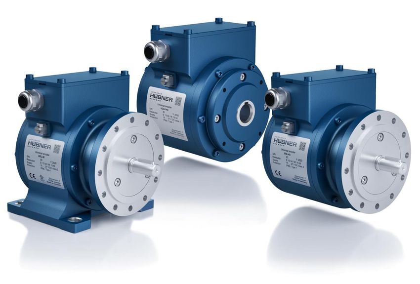
U-ONE®-LWL
Universal encoder system – Generation II
Read the operating and assembly manual before carrying out assembly, starting installa-
tion, or completing other work.
Store the manual for future use.
Translation of the original operating and assembly instructions Edition: 01 2021
ID 76612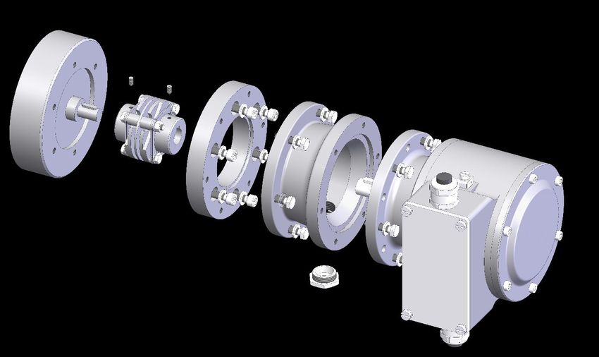
UOL 40 or UOLH 40
                                    Operating and assembly instructions

Manufacturer / author
Johannes Hübner                              Phone: +49 641 7969 0
Fabrik elektrischer Maschinen GmbH           Fax:         +49 641 73645
Siemensstr. 7                                Website:     www.huebner-giessen.com
35394 Giessen / Germany                      E-Mail:      info@huebner-giessen.com

Further current information on this product series is available online in our
Service Point.
Just scan the QR code and open the link in the browser.

These instructions and the enclosed declaration of conformity can also be accessed via our Ser-
vice Point. For this purpose, the QR code on the type plate of the corresponding device must be
scanned.

 2                                                                              UOL40_Manual-en_R1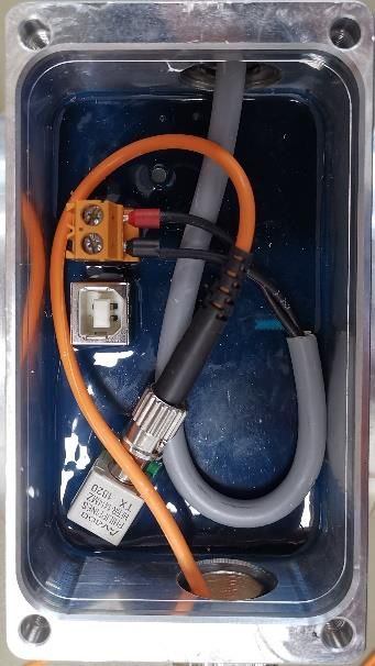
UOL 40 or UOLH 40
                                   Operating and assembly instructions

Trademark
Brand and product names are trademarks or registered trademarks of their respective owners.
Protected trademarks ™ or ® are not always designated as such in this manual.
However, this does not mean that they may be used freely.

Copyright protection
This operating and assembly manual, including the figures it contains, are copyright protected.
Third party usage of this operating and assembly manual in deviation from copyright regulations
is prohibited. The reproduction, translation or electronic and photographic archiving and amend-
ment of this manual shall require written approval by the manufacturer. Violations will result in
claims for damages.
Copyright © Johannes Hübner Fabrik elektrischer Maschinen GmbH

Reservation of rights
This operating and assembly manual has been prepared carefully. However, it may contain for-
mal errors or errors in content.
All rights reserved.

 UOL40_Manual-en_R1                                                                                 3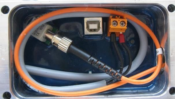
UOL 40 or UOLH 40
                                                 Operating and assembly instructions

Table of contents
1 General information ........................................................................................................ 6
  1.1 Information on the Operating and assembly manual ................................................... 6
  1.2 Scope of delivery ........................................................................................................ 6
  1.3 Explanation of symbols ............................................................................................... 6
  1.4 Warranty and liability .................................................................................................. 7
  1.5 Organisational measures ............................................................................................ 7
  1.6 Copyright protection ................................................................................................... 7
  1.7 Warranty provisions .................................................................................................... 7
  1.8 Customer service........................................................................................................ 8
2 Basic safety information ................................................................................................. 8
  2.1 Responsibility of the operator ..................................................................................... 8
  2.2 Selecting and qualifying personnel; basic obligations ................................................. 8
  2.3 Proper use .................................................................................................................. 9
  2.4 Improper use .............................................................................................................. 9
  2.5 Safety information..................................................................................................... 10
3 Assembly ....................................................................................................................... 11
  3.1 Safety information..................................................................................................... 11
  3.2 Technical information................................................................................................ 12
    3.2.1 Assembly for design B5 (flange) ........................................................................ 13
    3.2.2 Assembly for design B35 (flange and base) ....................................................... 14
    3.2.3 Installation of hollow shaft version ..................................................................... 15
  3.3 Disassembly ............................................................................................................. 17
    3.3.1 Disassembly of the UOL 40 ............................................................................... 17
    3.3.2 Exchanging the UOL 40 ..................................................................................... 17
  3.4 Installation ................................................................................................................ 18
    3.4.1 Basic regulations ............................................................................................... 18
    3.4.2 Electrical connection .......................................................................................... 18
4 Technical data ............................................................................................................... 20
  4.1 Type plate................................................................................................................. 20
  4.2 Type designation ...................................................................................................... 20
  4.3 Mechanical data ....................................................................................................... 21
    4.3.1 Solid shaft encoder ............................................................................................ 21
    4.3.2 Hollow shaft encoder ......................................................................................... 22
    4.3.3 Bearing service life ............................................................................................ 22
    4.3.4 Speed derating .................................................................................................. 23
  4.4 Electrical data ........................................................................................................... 23
  4.5 Operating modes and displays ................................................................................. 24
5 Structure and function .................................................................................................. 24
6 Inspections .................................................................................................................... 25
  6.1 Safety information..................................................................................................... 25
  6.2 Maintenance information .......................................................................................... 25
  6.3 Inspection plan ......................................................................................................... 25

 4                                                                                                             UOL40_Manual-en_R1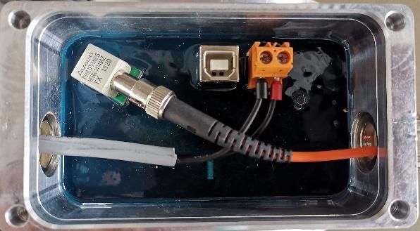
UOL 40 or UOLH 40
                                                 Operating and assembly instructions

7 Transportation, packaging and storage....................................................................... 26
  7.1 Transportation safety information ............................................................................. 26
  7.2 Incoming goods controlling ....................................................................................... 26
  7.3 Packaging (disposal) ................................................................................................ 26
  7.4 Storing packages (devices)....................................................................................... 26
  7.5 Returning equipment (repair/goodwill/warranty) ....................................................... 26
  7.6 Disposal ................................................................................................................... 27
8 Accessories ................................................................................................................... 28
  8.1 Solid shaft attachment .............................................................................................. 28
  8.2 Hollow shaft attachment ........................................................................................... 29
  8.3 Cable conduit systems.............................................................................................. 29
  8.4 Coupling for solid shaft installation............................................................................ 29
9 Documents..................................................................................................................... 30
  9.1 Dimensional drawings............................................................................................... 30
  9.2 Wiring diagram ......................................................................................................... 34

 UOL40_Manual-en_R1                                                                                                                     5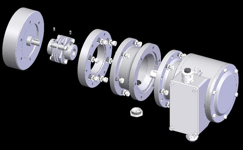
UOL 40 or UOLH 40
                                    Operating and assembly instructions

1 General information
1.1 Information on the Operating and assembly manual
    This operating and assembly manual provides important information on how to use the U-
    ONE-LWL standard basic unit. It must be read carefully before beginning any work and
    observed. The U-ONE-LWL standard basic unit is called UOL 40 in the following
    documentation.
    Furthermore, local accident prevention regulations and general safety regulations applicable
    in the area where the device is used must be observed.

1.2 Scope of delivery
    The scope of delivery for the UOL 40 includes fastening screws and washers as well as the
    operating and assembly manual.

1.3 Explanation of symbols
    Warning information is designated using symbols. Information is proceeded by signal words
    which express the extent of the danger involved. Always comply with these notices, and use
    caution to avoid accidents, personal injury and property damage.
           WARNING!
           Indicates a potentially hazardous situation that could lead to death or severe in-
           jury if it is not avoided.

           CAUTION!
           Indicates a potentially hazardous situation that could lead to minor or slight inju-
           ries if it is not avoided.

    !
           CAUTION!
           Indicates a potentially hazardous situation that could lead to property damage if it
           is not avoided.

           NOTE!
           Emphasises useful tips and recommendations, and provides information useful
           for efficient, smooth operation.

           NOTE!
           Using a hammer or similar tools during installation is not permitted, due to the
           danger of damage to the ball bearings and couplings.

6                                                                                UOL40_Manual-en_R1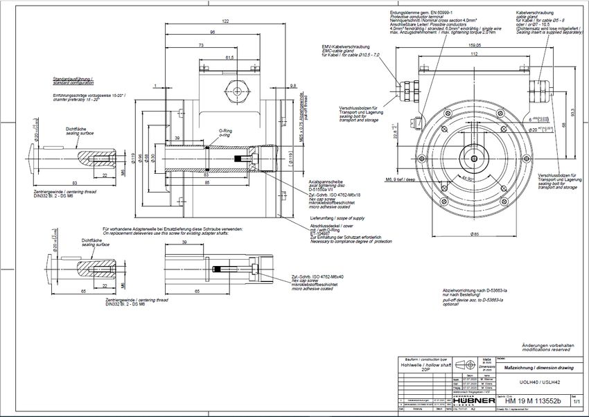
UOL 40 or UOLH 40
Operating and assembly instructions
1.4 Warranty and liability
Only the “General Terms and Conditions” of Johannes Hübner Fabrik elektrischer Maschinen
GmbH apply. These will be provided to the operator at the latest when the order is confirmed
or when the contract is concluded. All warranty and liability claims for personal injury and
property damage are excluded, and the operator's operating permit will be null and void if
one or more of the following apply:
Failure to observe the operating and assembly manual.
Improper use of the UOL 40
Improper assembly, installation, commissioning and programming of the UOL 40.
Improper work completed on the UOL 40
Operating the UOL 40 despite technical defects.
Independently carrying out mechanical or electrical modifications to the UOL 40.
Independently carrying out repairs.
Catastrophes due to external interference or force majeure.
Use of non-qualified personnel.
Opening the UOL 40 (except for the junction box) or completing conversions.
1.5 Organisational measures
The operating and assembly manual must always be stored easily within reach in the
area where the UOL 40 is used.
In addition to the operating and assembly manual, general statutory and other binding
regulations on accident prevention and environmental protection must be observed.
Operators must be trained on these regulations.
Applicable national, local, and system-specific provisions and requirements must be
observed.
The operator is obligated to inform personnel of special operating considerations and
requirements.
Personnel commissioned to complete work on the UOL 40 must read and familiarise
themselves with the operating and assembly manual before beginning work, in particular
section 2.
The type plate and any prohibitions or notice signs adhered to the UOL 40 must always
be legible.
Do not carry out mechanical or electrical modifications to the UOL 40, except for those
expressly described in this operating and assembly manual.
Repairs may only be carried out by the manufacturer, or by an agency or individual
authorised by the manufacturer.
1.6 Copyright protection
NOTE!
Content information, texts, drawings, images, and other illustrations are copyright
protected and subject to industrial property rights. Copying of any kind not asso-
ciated with use of the UOL 40 is prohibited without a written declaration from the
manufacturer. Violations will result in claims for damages.
1.7 Warranty provisions
Warranty provisions are outlined in the manufacturer's General Delivery Conditions.
UOL40_Manual-en_R1 7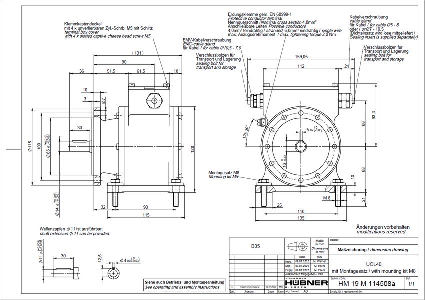
UOL 40 or UOLH 40
Operating and assembly instructions
1.8 Customer service
Contact persons are available by phone, fax, or e-mail for technical questions. See the
manufacturer’s address on page 2.
2 Basic safety information
DANGER!
This section provides an overview of all significant safety aspects necessary to
protect personnel and ensure safe, fault-free operation of the UOL 40. Failure to
observe this information may result in significant danger.
2.1 Responsibility of the operator
The UOL 40 is used in commercial areas. The operator of the UOL 40, therefore, is subject
to statutory occupational safety requirements and the safety, accident prevention and
environmental regulations applicable to the areas in which the UOL 40 is used.
2.2 Selecting and qualifying personnel; basic obligations
All work on the UOL 40 may be carried out only by qualified personnel. Qualified
personnel are personnel with the training, experience, and instruction, as well as
expertise on relevant standards, specifications, accident prevention regulations and
operating circumstances necessary to carry out the required work, and who have been
authorised to do so by the persons responsible for the safety of the system. They are
able to identify and avoid potential hazards.
In addition, please see standards VDE 0105-100 and IEC 364 for the definition of
“qualified personnel” (reference, e.g. Beuth Verlag GmbH, VDE-Verlag GmbH)
Responsibilities for assembly, installation, commissioning and operation must be clearly
defined. Personnel who are receiving instruction or training must be supervised.
8 UOL40_Manual-en_R1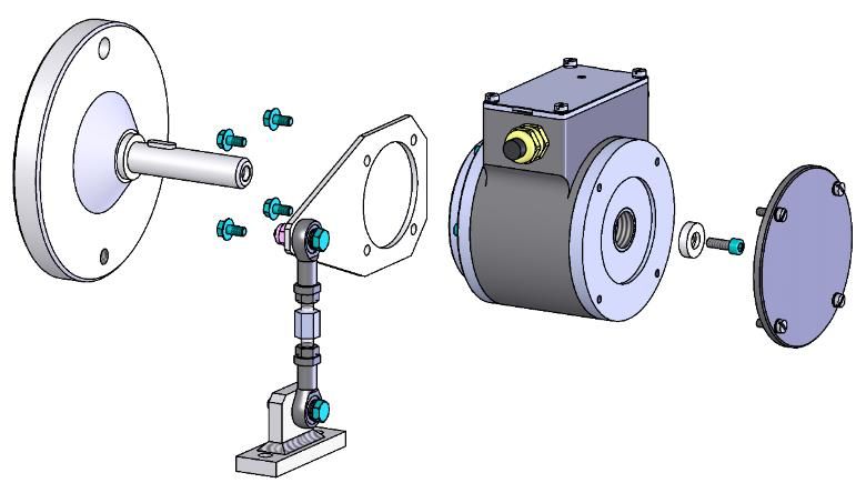
UOL 40 or UOLH 40
Operating and assembly instructions
2.3 Proper use
The UOL 40 can only be used in conjunction with the UO-ECU function module and other
function modules,
To record angular movements (with UO-EPB-1)
For position-dependent switching of potential-free relay contacts (UO-ERC-R)
For speed-dependent switching of potential-free relay contacts (UO-EGS-R)
For error-dependent switching of potential-free relay contacts (with UO-ERC-R or UO-
EGS-R)
.
The system manufacturer must review whether the properties of the UOL 40 fulfil the
requirements in its specific application. The system manufacturer is responsible for use of
the UOL 40 and for deciding whether to use the USL 42. The UOL 40 is designed for
unsupervised, continuous operation.
Proper use also includes:
observing all information in this operating and assembly manual
observing type plates and any prohibition or information signs attached to the UOL 40
observing the operating manual of the machine or system manufacturer
operating the UOL 40 within the limits stipulated in the technical data
secure (positive-locking) attachment of the UOL 40 to the drive axis
not engaging in improper use
2.4 Improper use
WARNING!
Danger of death, physical injury and property damage due to improper use of the
UOL 40!
In particular, the following uses are prohibited:
● Use in environments with an explosive atmosphere.
● Use in environments with radioactive radiation.
● Use on ships.
● Use for medical purposes.
● Attaching transportation or lifting equipment to the UOL 40 or load hooks to lift
a motor.
● Attaching packaging equipment to the UOL 40, such as belts, tarps, etc.
● Using the UOL 40 as a step, for instance to allow personnel to climb on a
motor.
UOL40_Manual-en_R1 9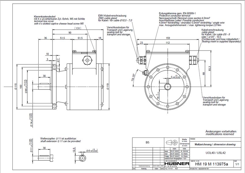
UOL 40 or UOLH 40
                                Operating and assembly instructions

2.5 Safety information
          WARNING! ATTENTION! NOTE!
          Destruction, damage or impact to the function of the UOL 40.
          ● Only complete wiring work and only connect or disconnect electrical
            connections when the USL 42 is powered down.
          ● Heating/cooling must be used at the installation location to prevent the device
            from falling below or exceeding the permitted ambient temperature limits.
          ● Review any potential hazards due to interactions with other systems and
            devices currently installed in the surrounding area, or which are to be
            installed. The user is responsible for taking relevant measures.
          ● The power supply must be secured with a fuse appropriate for the diameter of
            the intake line.
          ● Cables used must be suitable for the temperature range.
          ● A defective UOL 40 may not be operated.
          ● Ensure the installation area is protected against aggressive media (acids,
            etc.).
          ● Shocks (such as impact by a hammer) to the shaft are not permitted during
            assembly.
          ● The UOL 40 may not be used as a step, etc.
          ● Opening the UOL 40 is prohibited (except for the junction box).
          ● The type plate specifies the technical properties of the UOL 40. If the type
            plate is no longer legible, or if the type plate is missing entirely, the UOL 40
            may not be operated. Please contact Hübner service (see page 2).

10                                                                         UOL40_Manual-en_R1
UOL 40 or UOLH 40
Operating and assembly instructions
3 Assembly
3.1 Safety information
WARNING!
● Observe the safety information in section 2 during assembly, disassembly,
and other work on the UOL 40.
● All assembly, disassembly and other work on the UOL 40 may be carried out
only by qualified personnel.
DANGER! ATTENTION!
Danger of death, severe physical injury and/or property damage due to
deactivating safety functions, caused by an unsecured shaft drive.
● The system manufacturer or operator must design the system to ensure that
the drive shaft of the UOL 40 and the attachment (see chapter 3.2) of the UOL
40 are functional at all times (fault exclusion).
Observe the specifications of DIN EN 61800-5-2:2008 “Electrical power drives
with adjustable speed” – Safety requirements, table D.16 – Movement and
position sensors”.
● In general, the requirements and acceptance conditions for the system as a
whole must be observed.
Since the installation will differ depending on the application, the
following information may not necessarily be complete.
● All screws must be installed with the torque specified in the operating manual.
Setting processes must be avoided, due to the danger that the connection
may come loose. Screws must be tightened as necessary.
● Using the USL 42 at low ambient temperatures will result in increased starting
torque values. This must be taken into consideration when installing the shaft
drive.
● When using a coupling, the manufacturer's notices and installation
requirements must be observed.
UOL40_Manual-en_R1 11UOL 40 or UOLH 40
Operating and assembly instructions
3.2 Technical information
NOTE!
Using a hammer or similar tools during installation, disassembly and other work
on the UOL 40 is not permitted, due to the danger of damage to the ball bearings
and couplings.
Working temperature
The working temperature (housing temperature) must be within the permitted range (see sec.
4.3).
Protective class
The diameter of the connection cable must be appropriate for the cable glands and junction
box, in order to fulfil the protective class. (see section4.3)
The end cap must be installed in the hollow shaft version.
Ball bearing
The UOL 40 contains maintenance-free ball bearings with lifetime lubrication. The bearings
may only be exchanged by the manufacturer.
Screw lock
All attachment screws must be secured against unintentional loosening. We recommend
using Loctite® 243 (medium strength screw locking agent).
Required tools
Hex wrenches: Sizes 10, 13, 22
Allen keys: 5 mm, 6 mm
Flat screwdriver
Mounting grease
Loctite® 243 (medium strength screw locking agent)
Assembly preparation
1. Check accessories to ensure they are all present.
2. Preparing the installation site: Clean the drive shaft, centring, screw-fitting surfaces and
attachment threads and check them for damage. Repair any damage.
Personnel
Assembly and commissioning may only be carried out by qualified personnel.
NOTE!
Observe the safety information in section 2 during assembly and commissioning.
12 UOL40_Manual-en_R1UOL 40 or UOLH 40
Operating and assembly instructions
3.2.1 Assembly for design B5 (flange)
NOTE!
Example assembly (for dimensional drawing, see section 9).
The following assembly description is only an example, and may vary
depending on the type of coupling or flange used. The specific instructions of
the coupling manufacturer must be observed.
● The coupling must be mounted so it is easy to move. Adjust the drill holes for
used couplings if necessary.
● Mount the intermediate flange (4), so that the screw plug (16) points down, if
possible.
● For step 9, it may be necessary to turn the drive shaft (1) to the desired
position.
1
2
3
4
5
6
7
8
10
9
11 12
13
14
15
16
Fig. 3-1: Example design B5
1. Grease the drive shaft (1) lightly.
2. Mount the coupling (2) on the drive shaft (1).
3. Attach the coupling hub to the drive shaft (1) using a grub screw or regular screw (10)
(depending on the coupling design).
4. Attach the spacer (12) to the drive side using the attachment screws and washers (3).
5. Attach the intermediate flange (4) to the spacer (12) using the attachment screws (14)
and washers (14).
6. Grease the USL 42 shaft (6) lightly.
7. Insert the USL 42 (8) into the centring (15) and coupling hub (11) at the same time.
8. Fasten the USL 42 with at least 6 screws and washers (7) distributed evenly over the cir-
cumference of the flange (4).
9. Remove the screw plug (16) from the access opening (5) to the coupling.
UOL40_Manual-en_R1 13UOL 40 or UOLH 40
Operating and assembly instructions
10. Attach the coupling hub to the shaft using a grub screw or regular screw (10) (depending
on the coupling design).
11. Close the access opening on the intermediate flange (4) to the coupling using the screw
plug (16).
3.2.2 Assembly for design B35 (flange and base)
NOTE!
A UOL 40 version B35 can be attached using the flange (B5) or base (B3).
Example assembly (for dimensional drawing, see section 9).
The following assembly description is only an example, and may vary
depending on the type of coupling used. The specific instructions of the
coupling manufacturer must be observed.
The coupling (2) must be mounted so it is easy to move. Adjust the drill holes
for used couplings if necessary.
Angular errors and parallel misalignment between the drive shaft (1) and shaft
of the UOL 40 (4) are considered installation errors, and must be kept as
small as possible.
Installation errors:
- cause radial force to act on the UOL 40 shaft.
- reduce the service lives of the ball bearings and coupling.
- reduce signal quality (harmonics).
1
2
4 9 10
6
3
8
7
5
Fig. 3-2: Example design B35
14 UOL40_Manual-en_R1UOL 40 or UOLH 40
Operating and assembly instructions
1. Grease the drive shaft (1) lightly.
2. Attach the coupling hub (2) to the drive shaft (1) using a grub screw or regular screw (3)
(depending on the coupling design).
3. Grease the UOL 40 shaft (4) lightly.
4. Align the UOL 40 shaft (4) to the drive shaft (1) and mount on the coupling hub (6).
5. Attach the base of the UOL 40 to the customer interface (5) using 4 screws and match-
ing washers (7).
6. Attach the coupling hub to the shaft using a grub screw or regular screw (8) (depending
on the coupling design).
Attachment screws
The following conditions must be complied for proper assembly:
Tensile strength Screw Tightening torque
330…459 N/mm2 M8x40 - 12.9 26 Nm
> 460 N/mm2 M8x35 - 12.9 26 Nm
NOTE!
Appropriate measures must be taken if the minimum tensile strength on the
screw thread of the customer interface is not observed (for instance using Ensat
bushings).
3.2.3 Installation of hollow shaft version
NOTE!
Example assembly (for dimensional drawing, see section 9).
The following assembly description is only an example, and may vary depend-
ing on the type of adapter shaft used.
The radial run-out of the adapter shaft may be a max. of 0.05 mm.
Use the ball pressure screws to align the adapter shaft if necessary. Secure
the ball pressure screws with Loctite® 243 if necessary. Remove any ball
pressure screws that are not in use, or secure them with Loctite® 243 as well.
Use keys in accordance with DIN 6885.
The support arm (4) can be attached to the device in four different directions.
The hollow shaft device must be able to be pushed easily onto the adapter
shaft. Never used increased force to push it on; otherwise, this may damage
the bearings. Rework the adapter shaft and key using emery cloth or a file if
necessary. Do not strike the device hard against the shaft collar.
The torque arm must be able to turn easily around the joint head after assem-
bly. Failure to observe these requirements may result in bearing damage.
The ideal angle between the support arm (2) and the torque arm (9) is 90°.
The joint heads are maintenance-free, and must be kept free from contamina-
tion or paint.
UOL40_Manual-en_R1 15UOL 40 or UOLH 40
Operating and assembly instructions
1 3 2
5
6
7
8
9 4
10
1. Mount the adapter shaft (1) and align using a gauge.
2. Attach the support arm (2) to the hollow shaft encoder (4) using the included Tensilock
screws (3). Tightening torque: 16 Nm.
3. Loosen the 4 screws (8) to remove the cover (7).
4. Mount the hollow shaft encoder (4) onto the adapter shaft (1).
5. Secure the hollow shaft device using the enclosed axial conical spring washer (5) and
cylinder screw (6) (strength class 8.8). Tightening torque: 5.4 Nm.
6. Close the hollow shaft device using the cover or assembly kit for 2nd shaft end (7) and 4
screws (8).
7. Mounting the torque support:
Mounting without base plate:
The free joint head of the torque arm (9) is screwed directly onto a fixed point, for instance
onto the motor housing.
Mounting with base plate:
The base plate (10) is screwed onto a fixed point, such as the motor housing or the foun-
dation, using screws.
16 UOL40_Manual-en_R1UOL 40 or UOLH 40
Operating and assembly instructions
3.3 Disassembly
Disassembly may only be carried out by qualified personnel.
WARNING!
Observe the safety information in section 2 during disassembly, and other work on
the UOL 40.
NOTE!
Using a hammer or similar tools during disassembly is not permitted, due to the
danger of damage to the ball bearings and couplings.
3.3.1 Disassembly of the UOL 40
Before disassembly, unplug all electrical connection cables for the UOL 40.
Disassemble the UOL 40 in the reverse order indicated in section 3.
3.3.2 Exchanging the UOL 40
When replacing UOL 40, observe the following:
The new UOL 40 must have the same item no. (ID) as the old one.
Install the new UOL 40 according to the specifications and requirements of section 3.
When recommissioning the replaced UOL 40, a secure test run must be completed first
to ensure it functions correctly.
UOL40_Manual-en_R1 17UOL 40 or UOLH 40
Operating and assembly instructions
3.4 Installation
3.4.1 Basic regulations
WARNING!
● The power supply used must fulfil the requirements of SELV and PELV (IEC
60364-4-41).
● Potential equalisation measures must be taken throughout the entire
processing chain for the system.
● Ensure the energy supply is sufficient for the application.
● The diameter of the power supply line must be sufficient that the max. voltage
drop is < 3 V.
● When installing the cable, ensure there are no tripping hazards.
!
ATTENTION!
A cable must be connected to the ground terminal, for connection to the earth po-
tential.
3.4.2 Electrical connection
1. Strip the supply cable. The cable for the supply line is shielded, and the fibre optic cable
is not shielded. The cable cross section must be at least 0.8 mm2 and the cable diameter
must be at least 7 mm.
2. Crimp the wire end ferrules.
3. Open the junction box cover (9) (Fig. 3-2).
4. Remove the locking bolts on the cable glands (10) (Fig. 3-2). The cable gland for the
supply cable is an EMC cable gland.
5. Insert the cable through the cable glands into the junction box.
6. The shield on the supply line is connected directly with the housing using a cone
contactor via the EMC cable gland.
7. Tighten the cable glands until the cable is securely fixed in place and sealed.
8. Connect the supply voltage and fibre optic cable (see section 9.2).
9. If necessary, the cable glands can be exchanged. The cable must be installed in the
junction box as shown on the following images
10. Close the cover on the junction box.
18 UOL40_Manual-en_R1UOL 40 or UOLH 40
Operating and assembly instructions
NOTE!
No moisture may enter the junction box when the box is open.
Avoid tensile forces pulling the cables from the sides by ensuring the protec-
tive class of the cable glands is not negatively affected.
Cables should be routed in the form of a loop to prevent tensile force (see im-
age)
Before closing the cover on the junction box, check the sealing surface to en-
sure it is clean and check the seal to ensure it is complete. Clean or replace
damaged seals as necessary.
When closing the cover on the junction box, ensure that cables do not become
stuck.
UOL40_Manual-en_R1 19UOL 40 or UOLH 40
Operating and assembly instructions
4 Technical data
4.1 Type plate
The following image shows an example of a type plate.
The type plate is located on the outside of the
housing, and includes the following information:
Manufacturer, address
Type, year of construction
CE mark
Serial number (S/N)
Protective class
Supply voltage
ID number
Fig. 4-1: Type plate (example)
4.2 Type designation
UOL H 40
U-ONE-LWL
H: Hollow shaft 20P
20 UOL40_Manual-en_R1UOL 40 or UOLH 40
Operating and assembly instructions
4.3 Mechanical data
4.3.1 Solid shaft encoder
Information Value
Shaft load at the end of the
300 N axial, 300 N radial
shaft
Ø 14j6 x 30 mm
Shaft end
Ø 11j6 x 30 mm
Permitted speed 2800 1/min
Working temperature
-25°C…+ 67°C
(housing temperature)
Max. ambient temperature See chap. 4.3.4
Vibration resistance 10 g (DIN EN 60068-2-6:2008 (55 … 500 Hz))
Shock resistance, screw fit-
100 g (DIN EN 60068-2-27:2009 (half sine 11 ms)).
ting using M8 screws
Bearing service life
(see sec. 4.3.3) 3 x 10¹⁰ revolutions
Rotor moment of inertia approx. 330 gcm²
Permitted angular accelera-
104 rad/s²
tion
Breakaway torque approx. 3.5 Ncm
Protective class in accord-
IP66
ance with DIN EN 60529
Elevation above sea level 3000 m
Result. Noise emission level < 70 dB(A)
Design B5 approx. 3.6 kg
Weight Design B35 approx. 3.8 kg
UOL40_Manual-en_R1 21UOL 40 or UOLH 40
Operating and assembly instructions
4.3.2 Hollow shaft encoder
Information Value
Interior diameter 20 with keyway
Permitted speed 2800 1/min
Working temperature
-25°C…+ 67°C
(housing temperature)
Max. ambient temperature See chap. 4.3.4
Vibration resistance 10 g (DIN EN 60068-2-6:2008 (55 … 500 Hz))
Shock resistance 100 g (DIN EN 60068-2-27:2009 (half sine 11 ms))
Bearing service life
(see sec. 4.3.3) 1.2 x 10¹¹ revolutions
Rotor moment of inertia approx. 785 gcm²
Permitted angular accelera-
104 rad/s²
tion
Breakaway torque approx. 3.5 Ncm
Protective class in accord-
IP66
ance with DIN EN 60529
Noise emission level < 70 dB(A)
Max. elevation above sea
3000 m
level
Weight approx. 3.8 kg
4.3.3 Bearing service life
The service lives indicated are based on the calculation specifications of ISO/TS 16282, with
the following assumptions:
Continuous load throughout service life: 2000 1/min, 55°C
this means that the likelihood that the bearing will continue to function is 90%, based on the
given service lives.
The following factors influence the service life of the bearing
Operating temperature
Operating speed
Mechanical load due to vibrations and shocks
Drive dynamics
Influences of transportation and storage (bearing grease ageing)
Installation errors
22 UOL40_Manual-en_R1UOL 40 or UOLH 40
Operating and assembly instructions
4.3.4 Speed derating
The following derating curves are based on the average device speed.
4.4 Electrical data
Information Value
15 V…27 VDC in accordance with IEC 60364-4-41,
Supply voltage
SELV/PELV
Power consumptionUOL 40 or UOLH 40
Operating and assembly instructions
4.5 Operating modes and displays
Operating mode Status LED
flashing yellow/green
Start
2 Hz
Normal Green
Flashing yellow/red
Bootloader
1 Hz
Fault Red
5 Structure and function
The UOL 40 consists of optical Single-Turn scanning via a code disc with transmitted light,
magnetic Multi-Turn scanning and an integrated fibre optic interface. The fibre optic interface
transmits encoder data to the UO-ECU function module without errors. In addition, electronic
type plate and diagnostic data are also transmitted.
Data is then available in the UO-ECU function module as electrical signals.
24 UOL40_Manual-en_R1UOL 40 or UOLH 40
Operating and assembly instructions
6 Inspections
6.1 Safety information
NOTE / PERSONNEL
Only qualified personnel may inspect the UOL 40 and its installation.
Observe the safety information in section 2 during inspection and other work on
the UOL 40.
6.2 Maintenance information
The UOL 40 is maintenance-free. However, the following inspections are recommended to
ensure optimal, fault-free operation.
The inspections described here may be carried out only by technicians. Please observe, in
particular, operational and operator-relevant UV regulations, machine and system protec-
tion laws and application and country-specific specifications, laws and standards.
6.3 Inspection plan
NOTE!
No further work is required on the UOL 40, beyond the regular inspections
described in the following inspection plan. Any modifications to the UOL 40 will
result in a loss of all warranty claims!
Interval Inspections
Check coupling to ensure it is free from play and damage
Check the attachment screws to ensure they are tight
Check cable connections and terminals to ensure they are
Annual tight
Check the blind plugs to ensure they are sealed properly
Check labels and type plates to ensure they are legible
After approx. 16,000 to Check ball bearings to ensure they run smoothly and qui-
20,000 operating hours or etly. Ball bearings may only be replaced by the manufac-
heavy continuous loads turer.
UOL40_Manual-en_R1 25UOL 40 or UOLH 40
Operating and assembly instructions
7 Transportation, packaging and storage
7.1 Transportation safety information
CAUTION!
Property damage due to improper transportation!
! These symbols and information on the packaging must be observed:
Do not throw, danger of breakage
Protect against wetness
Protect against temperatures over 40°C and direct sunlight
7.2 Incoming goods controlling
The delivery must be checked promptly for transportation damage and to ensure it is
complete upon receipt.
If there is transportation damage, the carrier must be informed directly upon delivery. (Take
photos as evidence).
7.3 Packaging (disposal)
Packaging will not be taken back, and must be disposed of according to applicable statutory
specifications and local regulations.
7.4 Storing packages (devices)
Protect against wetness!
Protect packages against wetness, store in a dry and dust-free location.
Protect against heat
Protect packages against temperatures over 40°C and direct sunlight
In case of long storage times (> 6 months), we recommend packaging the devices in
protective packaging (with desiccants).
NOTE!
Turn the shaft of the UOL 40 every 6 months to prevent the grease from solidify-
ing.
7.5 Returning equipment
(repair/goodwill/warranty)
Service requests (repair/goodwill/warranty) can be initiated directly via the following online
form:
https://www.huebner-giessen.com/en/service-support/service/
There you will also find contact details for our service, as well as questions and answers
regarding the processing.
Devices that have come into contact with radioactive radiation or materials will not be taken
back.
Devices that have come into contact with biological or chemical substances that could be
hazardous to health must be decontaminated before they are returned. A clearance
certificate must be enclosed.
26 UOL40_Manual-en_R1UOL 40 or UOLH 40
Operating and assembly instructions
7.6 Disposal
The manufacturer is not obligated to take back the devices.
The UOL 40 must be treated as special electronic waste, and must be disposed of according
to specific national law.
Local municipal authorities or speciality disposal companies can provide information on
environmentally-appropriate disposal.
UOL40_Manual-en_R1 27UOL 40 or UOLH 40
Operating and assembly instructions
8 Accessories
In addition, we offer matching accessories and customised engineering support to ensure our
rotary encoder systems are robust and reliable.
8.1 Solid shaft attachment
We offer the following mechanical accessories for the solid shaft attachment, customised for
the individual attachment point:
Flange installation:
Couplings (single or double jointed couplings) with keyway for a secure, positive locking
connection
Intermediate flange incl. matching adapter disc as a mechanical interface to the machine
housing
Base installation:
Couplings (single or double jointed couplings) with keyway for a secure, positive locking
connection
28 UOL40_Manual-en_R1UOL 40 or UOLH 40
Operating and assembly instructions
8.2 Hollow shaft attachment
We offer the following mechanical accessories for the hollow shaft attachment, customised
for the individual attachment point:
Adapter shafts (flange or screw-in adapter shafts) with keyway for a secure, positive
locking connection
Torque supports with matching support arm and support lengths
8.3 Cable protection systems
We offer specially designed cable protection systems with screw fittings and sealing inserts,
as well as integrated shielding and strain relief in order to provide optimal protection for
rotary encoder wiring (copper, fibre optic cable) in extreme ambient conditions.
8.4 Couplings for solid shaft installation
We recommend our HK5 couplings, which are free from play and torsion-resistant, to attach
the UOL 40.
The couplings fulfill the following requirements:
Information Value
Torque 5 Nm
Max. speed 10000 1/min
Axial offset: ± 1 mm
HK 5 / HKI 5:
Installation Angle: 0.5°
precision
HKD 5 / HKDI Axial offset: ± 1.5 mm
5: Radial offset: ± 0.5mm
Our Sales department will be happy to provide you with further information.
UOL40_Manual-en_R1 29UOL 40 or UOLH 40
Operating and assembly instructions
9 Documents
9.1 Dimensional drawings
HM 19 M 114508a
30 UOL40_Manual-en_R1UOL 40 or UOLH 40
Operating and assembly instructions
HM 19 M 113975a
UOL40_Manual-en_R1 31UOL 40 or UOLH 40
Operating and assembly instructions
HM 19 M 113552b
32 UOL40_Manual-en_R1UOL 40 or UOLH 40
Operating and assembly instructions
HM 19 M 114598c
UOL40_Manual-en_R1 33UOL 40 or UOLH 40
Operating and assembly instructions
9.2 Wiring diagram
34 UOL40_Manual-en_R1You can also read