TRAFFIC SIGN COMPUTER AIDED DESIGN (TRASICAD V2.9.3) - USER MANUAL - TRANSPORT AND MAIN ROADS
←
→
Page content transcription
If your browser does not render page correctly, please read the page content below
User manual

Traffic Sign Computer Aided Design (TraSiCAD V2.9.3)
June 2020
Copyright
© The State of Queensland (Department of Transport and Main Roads) 2020.

Licence

This work is licensed by the State of Queensland (Department of Transport and Main Roads) under
a Creative Commons Attribution (CC BY) 4.0 International licence.

CC BY licence summary statement
In essence, you are free to copy, communicate and adapt this work, as long as you attribute the
work to the State of Queensland (Department of Transport and Main Roads). To view a copy of this
licence, visit: https://creativecommons.org/licenses/by/4.0/

Translating and interpreting assistance
              The Queensland Government is committed to providing accessible services to
              Queenslanders from all cultural and linguistic backgrounds. If you have difficulty
              understanding this publication and need a translator, please call the Translating and
              Interpreting Service (TIS National) on 13 14 50 and ask them to telephone the
              Queensland Department of Transport and Main Roads on 13 74 68.

Disclaimer
While every care has been taken in preparing this publication, the State of Queensland accepts no
responsibility for decisions or actions taken as a result of any data, information, statement or
advice, expressed or implied, contained within. To the best of our knowledge, the content was
correct at the time of publishing.

Feedback
Please send your feedback regarding this document to: tmr.techdocs@tmr.qld.gov.au

Traffic Sign Computer Aided Design (TraSiCAD V2.9.3), Transport and Main Roads, June 2020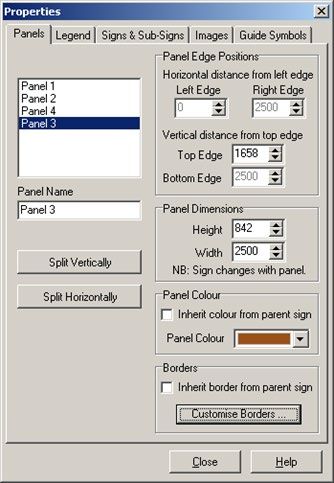
Contents

1      About this User Manual .................................................................................................................1
1.1    The Purpose of this Manual ............................................................................................................ 1
2      Using TraSiCAD .............................................................................................................................1
2.1    What is TraSiCAD? ......................................................................................................................... 1
2.2    Installing TraSiCAD ........................................................................................................................ 1
2.3    Opening TraSiCAD ......................................................................................................................... 2
2.4    Setting up defaults and options ...................................................................................................... 2
       2.4.1      Options ...........................................................................................................................2
2.5    Starting a drawing ........................................................................................................................... 6
       2.5.1      New ................................................................................................................................6
       2.5.2      Open ...............................................................................................................................7
       2.5.3      Use Wizard .....................................................................................................................7
       2.5.4      History bar ......................................................................................................................9
2.6    Drawing options .............................................................................................................................. 9
       2.6.1     Functions ........................................................................................................................9
       2.6.2     Adding a Legend ......................................................................................................... 14
       2.6.3     Adding a Road Name Patch ........................................................................................ 15
       2.6.4     Adding a Route Marker ............................................................................................... 16
       2.6.5     Adding Other Sub-Sign ............................................................................................... 16
       2.6.6     Adding an Image ......................................................................................................... 17
       2.6.7     Adding an Arrow Symbol ............................................................................................. 18
       2.6.8     Adding a Roundabout Symbol ..................................................................................... 19
       2.6.9     Adding a Diagrammatic Direction Symbol ................................................................... 22
2.7    Viewing options ............................................................................................................................. 25
       2.7.1     Zoom ........................................................................................................................... 25
       2.7.2     Gridlines Setup ............................................................................................................ 26
       2.7.3     Dimension .................................................................................................................... 27
       2.7.4     Sign Properties ............................................................................................................ 27
2.8    Saving a drawing .......................................................................................................................... 36
       2.8.1     Save As ....................................................................................................................... 37
       2.8.2     Save ............................................................................................................................ 37
       2.8.3     Export .......................................................................................................................... 38
2.9    Printing .......................................................................................................................................... 39
       2.9.1         Printer Setup ................................................................................................................ 39
       2.9.2         Page Setup .................................................................................................................. 39
       2.9.3         Print Preview ............................................................................................................... 42
       2.9.4         Print ............................................................................................................................. 44
       2.9.5         Sign Object Viewer ...................................................................................................... 44
2.10 Closing a drawing ......................................................................................................................... 45
3      Licensing ..................................................................................................................................... 47
3.1    Licensing details ........................................................................................................................... 47
3.2    Extension of licence ...................................................................................................................... 48
3.3    Transfer of licence ........................................................................................................................ 49
3.4    Frequently asked questions .......................................................................................................... 50

Traffic Sign Computer Aided Design (TraSiCAD V2.9.3), Transport and Main Roads, June 2020                                                                   i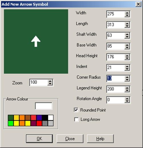
Tables

Table 2.5.3 – Wizard selection process .................................................................................................. 8

Table 2.6.1.4 – Align process ................................................................................................................ 11

Table 2.6.6 – Add: Image From File ...................................................................................................... 17

Table 2.6.9 – Diagrammatic direction symbols process areas.............................................................. 23

Table 3.2 – Unlock Code process ......................................................................................................... 48

Table 3.3 – Transferring TraSiCAD process ......................................................................................... 50

Table 3.4 – Frequently asked questions ............................................................................................... 50

Figures

Figure 2.3 – TraSiCAD working screen ................................................................................................... 2

Figure 2.4.1.1 – Options screen .............................................................................................................. 2

Figure 2.4.1.2 – Edit screen .................................................................................................................... 3

Figure 2.4.1.3(a) – New sign: Default legend .......................................................................................... 4

Figure 2.4.1.3(b) – New sign: Default print settings screen .................................................................... 4

Figure 2.4.1.3(c) – New sign: Default title block settings screen ............................................................ 5

Figure 2.4.1.4 – Display screen ............................................................................................................... 5

Figure 2.5 – Accessing drawings from the File directory ........................................................................ 6

Figure 2.5.1 – New screen options .......................................................................................................... 6

Figure 2.5.2(a) – Open screen option: Opening a previously designed sign .......................................... 7

Figure 2.5.2(b) – Open screen option: Accessing the Signs directory .................................................... 7

Figure 2.5.2(c) – Examples of signs available in TraSiCAD Signs directory. ......................................... 7

Figure 2.5.4 – History bar ........................................................................................................................ 9

Figure 2.6.1 – Drawing options in Edit menu .......................................................................................... 9

Figure 2.6.1.3 – Add options to insert in a drawing ............................................................................... 10

Figure 2.6.1.5(a) – Adjust: Apply Clearance Rules option .................................................................... 13

Figure 2.6.1.5(b) – Adjust: Reduce Sign option .................................................................................... 13

Figure 2.6.2(a) – Add shortcut ............................................................................................................... 14

Figure 2.6.2(b) – Legend option: Add to Panel ..................................................................................... 14

Figure 2.6.2(c) – Australian Standard fonts........................................................................................... 15

Figure 2.6.3 – Road Name Patch option: Add to Panel ........................................................................ 15

Figure 2.6.4 – Route Marker option: Add to Panel ................................................................................ 16

Figure 2.6.5 – Other Sub-Sign option: Add to Panel ............................................................................. 16

Traffic Sign Computer Aided Design (TraSiCAD V2.9.3), Transport and Main Roads, June 2020                                                          ii
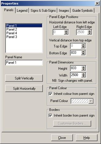
Figure 2.6.6 – Image From File option: Add to Panel ........................................................................... 17

Figure 2.6.7(a) – Arrow Symbol option: Add to Panel ........................................................................... 18

Figure 2.6.7(b) – Full colour palette ...................................................................................................... 19

Figure 2.6.8(a) – Roundabout Symbol Option: Add to Panel ................................................................ 19

Figure 2.6.8(b) – Manual sizing via Leg Details .................................................................................... 21

Figure 2.6.9(a) – Diagrammatic Direction Symbol option: Add to Panel ............................................... 22

Figure 2.6.9(b) – Add New Diagrammatic Direction Symbol option ...................................................... 22

Figure 2.6.9(c) – Base Branch Segments ............................................................................................. 23

Figure 2.6.9(d) – Add Branch option ..................................................................................................... 24

Figure 2.6.9(e) – Depiction of multiple segments .................................................................................. 24

Figure 2.6.9(f) – Edit Branch option ...................................................................................................... 24

Figure 2.7 – View directory options ....................................................................................................... 25

Figure 2.7.1 – Zoom option ................................................................................................................... 25

Figure 2.7.2 – Gridlines Setup option .................................................................................................... 26

Figure 2.7.2.1 – Show Grid option ......................................................................................................... 26

Figure 2.7.2.2 – Snap to Grid option ..................................................................................................... 27

Figure 2.7.3 – Dimension option ........................................................................................................... 27

Figure 2.7.4 – Sign Properties option example ..................................................................................... 28

Figure 2.7.4.1 – Panels tab ................................................................................................................... 29

Figure 2.7.4.2 – Legend tab .................................................................................................................. 30

Figure 2.7.4.3 – Images tab................................................................................................................... 30

Figure 2.7.4.4 – Guide Symbol tab ........................................................................................................ 31

Figure 2.7.4.5(a) – Signs & Sub-signs tab ............................................................................................ 32

Figure 2.7.4.5(b) – Auto Resize Route Markers and Road Name Patches check box ......................... 32

Figure 2.7.4.6(a) – New multi-panel sign .............................................................................................. 33

Figure 2.7.4.6(b) – Clearance applied to new multi-panel sign ............................................................. 33

Figure 2.7.4.6(c) – Example of independent panel colour change ....................................................... 34

Figure 2.7.4.6(d) – Deselection of Inherit colour from parent sign ........................................................ 34

Figure 2.7.4.6(e) – Different coloured border in separate panel ........................................................... 34

Figure 2.7.4.7(a) – Inherit panel colours, border widths and colours .................................................... 35

Figure 2.7.4.7(b) – Independent change of panel colours and border widths and colours ................... 35

Figure 2.7.4.7(c) – Example of external border colour control .............................................................. 36

Figure 2.8.1(a) – Save As selection ...................................................................................................... 37

Traffic Sign Computer Aided Design (TraSiCAD V2.9.3), Transport and Main Roads, June 2020                                                       iii
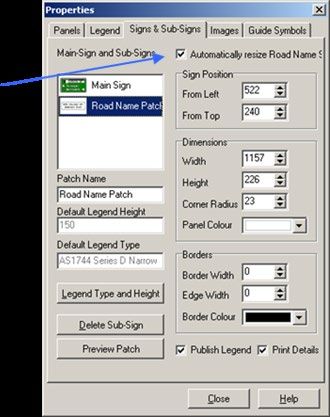
Figure 2.8.1(b) – Save As alternate selection ....................................................................................... 37

Figure 2.8.2 – Save selection ................................................................................................................ 38

Figure 2.8.3 – Export selection .............................................................................................................. 38

Figure 2.9.1 – Printer Setup selection ................................................................................................... 39

Figure 2.9.2 – Page Setup selection ..................................................................................................... 39

Figure 2.9.2.1 – Page Setup>Layout tab .............................................................................................. 40

Figure 2.9.2.2(a) – Page Setup>Title Block selection ........................................................................... 40

Figure 2.9.2.2(b) – Add Materials option ............................................................................................... 41

Figure 2.9.2.3 – Page Setup>Margins selection ................................................................................... 42

Figure 2.9.3 – Print Preview selection ................................................................................................... 42

Figure 2.9.3.2 – Print Preview>Next option ........................................................................................... 43

Figure 2.9.4 – Print selection ................................................................................................................. 44

Figure 2.9.5 – Sign Object Viewer selection ......................................................................................... 44

Figure 2.9.5.1 – Sign Object Viewer>Create List option ....................................................................... 45

Figure 2.10 – Close selection ................................................................................................................ 46

Figure 3.1(a) – Licensing details ........................................................................................................... 47

Figure 3.1(b) – Register TraSiCAD selection ........................................................................................ 47

Figure 3.1(c) – Unlock TraSiCAD .......................................................................................................... 48

Traffic Sign Computer Aided Design (TraSiCAD V2.9.3), Transport and Main Roads, June 2020                                                        iv
User manual

1     About this User Manual
1.1       The Purpose of this Manual

      •    Audience: This User Manual is intended for designers using the Traffic Sign Computer Aided
           Design (TraSiCAD) software program for the design of signs.

      •    Scope: The User Manual describes the process involved to:

               −   create new signs within standard guidelines

               −   produce designs for manufacture, and

               −   interpret messages, warnings and errors.

      •    Reader skills: The User Manual assumes that the reader has a basic knowledge of

               −   personal computers

               −   Australian Standard AS 1743 Road Signs – Specifications, and

      •    Expected outcomes: After studying this User Manual, the reader should be able to

               −   create new signs

               −   understand sign clearances, and

               −   print drawings.

2     Using TraSiCAD
2.1       What is TraSiCAD?
TraSiCAD is a program developed by the Department of Transport and Main Roads to assist in the
design of road signs.

This User Manual is intended to be used in conjunction with:

      •    Australian Standard AS 1743 Road Signs – Specifications

      •    Australian Standard AS 1744 Standard Alphabets for Road Signs, and

      •    The Queensland Manual of Uniform Traffic Control Devices (MUTCD).

More information can be found at:

https://www.tmr.qld.gov.au/business-industry/Road-systems-and-engineering/Software/TraSiCAD.

2.2       Installing TraSiCAD

Go to https://www.tmr.qld.gov.au/business-industry/Road-systems-and-
engineering/Software/TraSiCAD.

      •    Find Install_TraSiCAD_v2.930.zip file.

      •    Save to a relevant folder on your local drive and unzip it.

      •    Run Install_TraSiCAD_v2.930.msi.

TraSiCAD will automatically set up all files.

Follow all prompts until completed, then select Finish.

Traffic Sign Computer Aided Design (TraSiCAD V2.9.3), Transport and Main Roads, June 2020               1
User manual

2.3     Opening TraSiCAD

After installation has been completed, open the program by either:

      1. running from the executable file in the directory in which the program was installed, or

      2. double click on the TraSiCAD icon developed on the computer desktop during the installation.

The TraSiCAD working screen, as shown in Figure 2.3, will appear.

Figure 2.3 – TraSiCAD working screen

Note: TraSiCAD has its own complete Help function that may be used in conjunction with this User Manual.

2.4     Setting up defaults and options

TraSiCAD can set various default options required during the drawing design process. Before using
TraSiCAD, the various options can be set up with default characteristics.

For faster and more efficient use of the program, these options should be set prior to the
commencement of any design.

2.4.1     Options

From the Tools directory, select Options.

This opens a dialogue box with four tab functions: General, Edit, New sign and Display.

2.4.1.1    General

Figure 2.4.1.1 shown the General screen.

Figure 2.4.1.1 – Options screen

Traffic Sign Computer Aided Design (TraSiCAD V2.9.3), Transport and Main Roads, June 2020                  2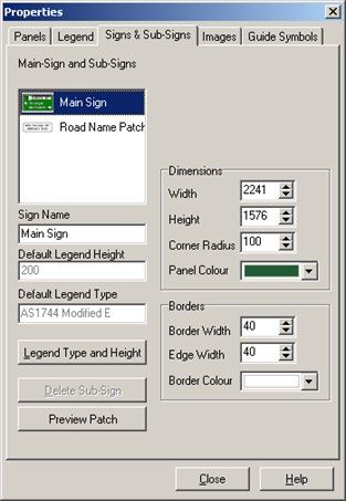
User manual

The General tab:

    •     gives the option of selecting parameters with particular RTA characteristics

    •     accesses the clearance rule set* that determines the particular clearance rules for the
          elements within the sign

    •     sets the order in which clearances are made

    •     allows automatic setting of borders and corner radii when clearance rules are applied, if
          required, and

    •     redirects the default sign saving directory to user defined, if required.
* These rule sets are based on AS 1743 and should not be modified unless there are valid design reasons. It is
essential that the appropriate rule set is selected for correct clearances. There are two options available:
              •   AS1743 Dark_on_Light (for dark legend on light background)
              •   AS1743 Light_on_Dark (for light legend on dark background).

2.4.1.2    Edit

Figure 2.4.1.2 shows the Edit screen.

Figure 2.4.1.2 – Edit screen

The Edit tab:

    •     varies the nudge distance of elements on the sign face

    •     achieves fine control of element placement by using the UP / DOWN / LEFT / RIGHT arrows
          on the keyboard

    •     allows selection of copying file types

    •     selects the number of Undo functions available, and

    •     can decide if the Undo / Redo stack is reset or not after a Save function has been completed.

Traffic Sign Computer Aided Design (TraSiCAD V2.9.3), Transport and Main Roads, June 2020                        3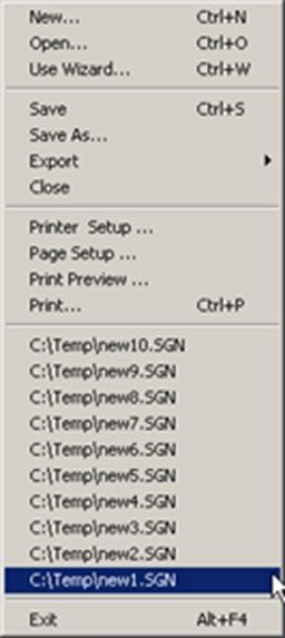
User manual

2.4.1.3    New sign

Figure 2.4.1.3(a) shows the New sign: Default legend screen.

Figure 2.4.1.3(a) – New sign: Default legend

The Default legend option:

    •     sets the Default legend height which sets clearances consistent with the rule set being used

    •     enables the setting of default legends for the various signs and route markers used with the
          various wizards, and

    •     should be completed prior to using TraSiCAD.

Figure 2.4.1.3(b) shows the New sign: Default print settings screen.

Figure 2.4.1.3(b) – New sign: Default print settings screen

The Default print settings option:

    •     selects the ability to show arrow heads in dimensions

    •     selects the default printing scales

    •     sets the default print margins, and

    •     sets the default font for the print title block.

Traffic Sign Computer Aided Design (TraSiCAD V2.9.3), Transport and Main Roads, June 2020                4
User manual
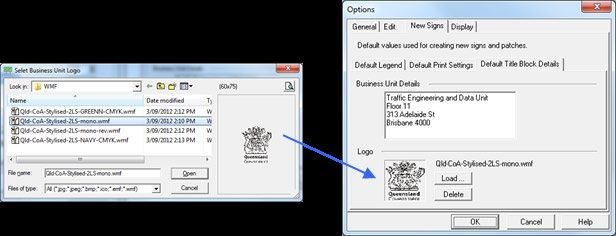
Figure 2.4.1.3(c) shows the New sign: Default title block settings screen.
Figure 2.4.1.3(c) – New sign: Default title block settings screen
The Default title block settings option:
• sets default Business Unit Details, and
• loads / deletes a pre-designed logo as a default for use in the print title block.
2.4.1.4 Display
Figure 2.4.1.4 shows the Display screen.
Figure 2.4.1.4 – Display screen
The options on this screen set the colouring characteristics of TraSiCAD when non-system colours are
displayed and represented.
When using a display device with a colour palette smaller than 24 bits, some colours will not be
available in the device palette and will need to be approximated. Two methods are available:
• closest match – colours are represented by the closest matching colour from the logical
palette of the display device, and
• dithering – colours are represented by drawing a pattern using similar colours.
Traffic Sign Computer Aided Design (TraSiCAD V2.9.3), Transport and Main Roads, June 2020 5User manual 2.5 Starting a drawing There are four different methods of accessing drawings within the TraSiCAD program, as shown in Figure 2.5. Figure 2.5 – Accessing drawings from the File directory Selecting the File directory indicates New, Open, Use Wizard or the file history bar. Note: Once a drawing has been commenced, it is recommended that the Sign Properties Feature (Alt+P) is used to enter user-nominated variables (see Section 2.7.4). 2.5.1 New Figure 2.5.1 shows the screens that appear when New is selected. Figure 2.5.1 – New screen options These options are used to develop new signs, using basic styles and backgrounds. There are up to 16 different styles that are selectable from this box. Traffic Sign Computer Aided Design (TraSiCAD V2.9.3), Transport and Main Roads, June 2020 6
User manual

2.5.2   Open

Figure 2.5.2(a) shows the screen that appears when Open is selected.

Figure 2.5.2(a) – Open screen option: Opening a previously designed sign

This option is used to open a previously designed sign from a file directory. This option can be used to
modify, copy or print previously designed signs selected from the user’s specific local or network files
and directories (see Section 2.4.1.1).

Alternately, the Open option can be used to access the specific Signs directory within TraSiCAD, as
shown in Figure 2.5.2(b).

Figure 2.5.2(b) – Open screen option: Accessing the Signs directory

This directory contains a number of signs, as shown in Figure 2.5.2(c).

Figure 2.5.2(c) – Examples of signs available in TraSiCAD Signs directory.

After clearance with AS 1743 Light_on_Dark ruleset, borders and external and internal corners are reset.

2.5.3   Use Wizard

Table 2.5.3 details the steps and shows the screens that appear when the Use Wizard option is
selected. This option is used to select a particular type of sign from a list of wizards (Roads and
Maritime Services (RMS) selection if needed, see Section 2.5.1). This gives a specific design of a sign
which will be set out according to predetermined standard format and style.

Traffic Sign Computer Aided Design (TraSiCAD V2.9.3), Transport and Main Roads, June 2020                  7
User manual

Table 2.5.3 – Wizard selection process

          Wizard step                                      Screen illustration
 Select required Wizard
 (depending on the
 installation used (RMS or
 Transport and Main Roads),
 an example window indicates
 the type of sign to be
 selected)
                                     RMS selection                     Transport and Main Roads
                                                                       selection
 Select number of panels (if
 available), the particular
 legend type and height.
 Note: The legend value selected
 only assigns the characteristics
 for the legends on that sign and
 has no bearing on the Default
 legend height value that set the
 clearance values between the
 elements on that sign.

 For each of the panels
 requested in the previous
 step, select and apply details
 for a Road Name Patch,
 Route Marker type and
 number, Arrow type and
 Legend.
 Note: To assist with drawing
 efficiency, the subsequent use of
 any wizard allows the user to
 use previously entered values of
 a wizard when it was last run.
 For example, if a three-panelled
 wizard design was initially used
 and there was a requirement for
 a subsequent two-panel sign,
 any of the legends or symbols
 from the first two panels may be
 selected for use in that new
 design

Traffic Sign Computer Aided Design (TraSiCAD V2.9.3), Transport and Main Roads, June 2020         8
User manual 2.5.4 History bar Figure 2.5.4 shows the screens that appear when the History bar option is selected. Figure 2.5.4 – History bar This option is used to select up to 10 previously designed drawings without needing to close a current drawing. 2.6 Drawing options 2.6.1 Functions Drawing options are available in the Edit menu, as shown in Figure 2.6.1. Modifications, additions and adjustments can be made to any sign drawing. Figure 2.6.1 – Drawing options in Edit menu Traffic Sign Computer Aided Design (TraSiCAD V2.9.3), Transport and Main Roads, June 2020 9
User manual

The functions dialogue box gives access to options which include:

    •     Undo

    •     Redo

    •     Add

    •     Align

    •     Adjust

    •     Copy

    •     Cut

    •     Paste

    •     Paste Special, and

    •     Delete.

Selection from this list in the Edit directory or using the associated short cut keys will use the functions
as follows.

2.6.1.1    Undo

The Undo function undoes the last number of drawing steps carried out (Undo levels are set in the
Tools directory under Options / Edit – see Section 2.4.1.2).

2.6.1.2    Redo

The Redo function redoes the previous Undo function. Redo levels are limited by the amount of Undo
levels.

2.6.1.3    Add

The Add function facilitates the addition of various items to be inserted in a drawing, as shown in
Figure 2.6.1.3.

Figure 2.6.1.3 – Add options to insert in a drawing

Traffic Sign Computer Aided Design (TraSiCAD V2.9.3), Transport and Main Roads, June 2020                10
User manual
Items are:
• Legend
• Road Name Patch
• Route Marker
• Other Sub-Sign
• Image From File (see Section 2.6.6)
• Arrow Symbol (see Section 2.6.7)
• Roundabout Symbol (see Section 2.6.8), and
• Diagrammatic Direction Symbol (see Section 2.6.9).
2.6.1.4 Align
The Align function allows for the horizontal or vertical alignment of two or more separate items on a
drawing.
Note: All preselected items will be aligned to the last item selected in the Align process, which is detailed in
Table 2.6.1.4.
Table 2.6.1.4 – Align process
Step Screen illustration
Alignment of two single items
Select the first item to be aligned to another.
Hold down the Shift key and select the
second item.
Select Edit directory, then Align (or Ctrl L).
An Alignment Tool dialogue box will appear.
Select the relevant Horizontally (Top,
Centre or Bottom) or Vertically (Left,
Centre or Right) alignment box.
The items will appear aligned on the screen.
Select OK.
The sign will be permanently aligned and
updated in the drawing.
Vertical alignment of multiple legends (for example, Rest Area and 1km)
Quantity items may be made up of
two separate 'words' (for example, '1' and
'km'). To correctly align these separated
quantity items with other legends, select the
number '1'
Hold the Shift key then select 'km'.
While still holding the Shift key, select the
legend 'Rest Area' to which the quantity item
is to be aligned.
Traffic Sign Computer Aided Design (TraSiCAD V2.9.3), Transport and Main Roads, June 2020 11User manual
Step Screen illustration
Select Edit directory, then Align (Ctrl L)
where an Alignment Tool dialogue box will
appear.
Select the Group Into Rows box. This will
group select the '1' and the 'km.' This will be
indicated on the screen with dotted box
enclosing both items selected.
Select Centre for a centre alignment. A
position measurement indicator will appear
signifying the centre position of the new
alignment line. Manual modifications to this
position measurement can be made in this
box if required by direct editing or using the
up / down arrows.
Select OK to generate the newly aligned sign.
2.6.1.5 Adjust
The Adjust function sets the automatic adjustment of items on the sign face at predetermined
clearances. Two separate options are available: Apply Clearance Rules and Reduce Sign.
The Apply Clearance Rules option is shown at Figure 2.6.1.5(a).
Traffic Sign Computer Aided Design (TraSiCAD V2.9.3), Transport and Main Roads, June 2020 12User manual Figure 2.6.1.5(a) – Adjust: Apply Clearance Rules option The Apply Clearance Rules option enforces an automatic clearance on all items on the drawing to give predetermined spacing from rules installed within TraSiCAD. These rules can be found in the Rule Editor in the Options directory (see Section 2.4.1.1). Note: Clearances are determined by the 'Default legend' size and not the size of the legend being used on the drawing. The Reduce Sign option is shown at Figure 2.6.1.5(b). Figure 2.6.1.5(b) – Adjust: Reduce Sign option The Reduce Sign option completely reduces the sign to its smallest size, taking into consideration and applying clearance rules formulated in the rule sets previously mentioned in Section 2.4.1.1. It will set the borders and corner radii to the appropriate values if the particular requested boxes are checked in the Options / General dialogue box (see Section 2.4.1.1). 2.6.1.6 Copy The Copy function takes a copy of the selected item on the drawing and places it on a working clipboard to be reused on that drawing or in other compatible software applications. The copied item remains intact on the drawing. 2.6.1.7 Cut The Cut function takes a copy of the selected item before erasing it from the drawing. It places it on a working clipboard to be reused on that drawing or in other compatible software applications. This function can also be used as a Delete. Note: The working clipboard will only hold one item at a time. If another object is subsequently cut or copied, the previous object will be overwritten, depending on the number of Undo levels. 2.6.1.8 Paste The Paste function places the object obtained by the last Cut or Copy function from the working clipboard onto the present working drawing. Traffic Sign Computer Aided Design (TraSiCAD V2.9.3), Transport and Main Roads, June 2020 13
User manual

2.6.1.9     Paste Special

The Paste Special function enables two separate ways to import items from the clipboard of other
Windows applications.

    •     Paste Text as a Legend: Takes text copied or cut to the clipboard from other compatible
          applications and places it on the working drawing in a text editable format.

    •     Paste Metafile as Image: Imports an object or text copied or cut to the clipboard from other
          compatible applications and places it on the working drawing in a non-editable form. This is
          ideal for quickly importing logos and symbols from electronic brochures.

2.6.1.10 Delete

The Delete function deletes any object from the drawing. This option does not use the working
clipboard; therefore, the object will be deleted permanently. The Undo function will undelete any
object deleted, depending on the amount of Undo levels set in the Options / Edit box (see
Section 2.4.1.2)

2.6.2     Adding a Legend
Note: The Add function can be activated in shortcut mode by placing the cursor somewhere on the active drawing
and right-clicking the mouse. A dialogue box with four options, including Add, as shown in Figure 2.6.2(a), will
appear on the drawing.

Figure 2.6.2(a) – Add shortcut

Selecting Legend, as shown in Figure 2.6.2(b), allows specified words to be imported into the drawing
from the ensuing Add to Panel dialogue box. Particular Legend types and heights can be selected as
required.

Figure 2.6.2(b) – Legend option: Add to Panel

Traffic Sign Computer Aided Design (TraSiCAD V2.9.3), Transport and Main Roads, June 2020                    14
User manual
Note that all fonts used in TraSiCAD are derived from any font in the C:\Windows\Fonts directory. All Australian
Standard fonts, as shown in Figure 2.6.2(c) (sold separately to the TraSiCAD software), should be installed in that
directory.
Figure 2.6.2(c) – Australian Standard fonts
2.6.3 Adding a Road Name Patch
Note: The Add function can be activated in shortcut mode by placing the cursor somewhere on the active drawing
and right-clicking the mouse. A dialogue box with four options, including Add, as previously shown in
Figure 2.6.2(a), will appear on the drawing.
Selecting Road Name Patch, as shown in Figure 2.6.3, allows one of the following specified shaped
patches to be imported into the drawing from the ensuing Add to Panel dialogue box.
Figure 2.6.3 – Road Name Patch option: Add to Panel
Sign shape options are:
• Not Pointed
• Left Pointed
• Right Pointed, or
• Double Pointed.
Note: The Legend Height used in a Road Name Patch is automatically reduced to 75% of the main sign Legend
Height.
Traffic Sign Computer Aided Design (TraSiCAD V2.9.3), Transport and Main Roads, June 2020 15User manual
2.6.4 Adding a Route Marker
Note: The Add function can be activated in shortcut mode by placing the cursor somewhere on the active drawing
and right-clicking the mouse. A dialogue box with four options, including Add, as previously shown in
Figure 2.6.2(a), will appear on the drawing
Selecting Route Marker, as shown in Figure 2.6.4, allows one of six different types of markers to be
imported into the drawing from the ensuing Add to Panel dialogue box.
Figure 2.6.4 – Route Marker option: Add to Panel
Route marker options are:
• Alpha-Numeric Route Marker
• Tourist Route Marker
• State Route Marker
• Metroad Route Marker
• National Highway Route Marker, or
• National Route Marker.
2.6.5 Adding Other Sub-Sign
Note: The Add function can be activated in shortcut mode by placing the cursor somewhere on the active drawing
and right-clicking the mouse. A dialogue box with four options, including Add, as previously shown in
Figure 2.6.2(a), will appear on the drawing.
Selecting Other Sub-sign from the Add to Panel box, as shown in Figure 2.6.5, allows a selection of
signs to be imported from the ensuing New Sign dialogue box to be placed into the main sign.
Multi-sub-signs may be selected. A number of sub sign panel options are available for selection from
the New Sign dialogue box.
Figure 2.6.5 – Other Sub-Sign option: Add to Panel
Traffic Sign Computer Aided Design (TraSiCAD V2.9.3), Transport and Main Roads, June 2020 16User manual
2.6.6 Adding an Image
Note: The Add function can be activated in shortcut mode by placing the cursor somewhere on the active drawing
and right-clicking the mouse. A dialogue box with four options, including Add, as previously shown in
Figure 2.6.2(a), will appear on the drawing.
Selecting Image From File from the Add to Panel box, as shown in Figure 2.6.6, allows specialised
image files to be imported into the drawing from the ensuing Open browse dialogue box.
Figure 2.6.6 – Image From File option: Add to Panel
TraSiCAD accesses internal directories of .wmf or .emf symbol files to be directly imported onto the
sign face. Selecting Add: Image From File will usually directly access the Symbols library within the
TraSiCAD program. In a typical installation this file location will be C:\Program Files
(x86)\TMR\TraSiCAD\Symbols.
Note: TraSiCAD allows import of any .emf or .wmf files. If other self-generated symbols files are designed, they
may be placed in this directory for convenience or located in other dedicated directory locations.
The process to Add: Image From File is shown in Table 2.6.6.
Table 2.6.6 – Add: Image From File
Step Screen illustration
Select the required symbol.
Select Open.
An Add Image dialogue box will appear,
indicating the symbol selected. The height and
width are shown, along with a scaling option to
increase or reduce the importing size to suit the
sign dimension requirements.
Options to OK, Change (revert to the previous
dialogue box for alternative selection) or Cancel
the symbol are available.
Traffic Sign Computer Aided Design (TraSiCAD V2.9.3), Transport and Main Roads, June 2020 17User manual
2.6.7 Adding an Arrow Symbol
Note. The Add function can be activated in shortcut mode by placing the cursor somewhere on the active drawing
and right-clicking the mouse. A dialogue box with four options, including Add, as previously shown in
Figure 2.6.2(a), will appear on the drawing.
Various types and sizes of arrows can be added to a panel by selecting Arrow Symbol in the Add to
Panel X of Main Sign box and the ensuing Add New Arrow Symbol dialogue box, as shown in
Figure 2.6.7(a).
Figure 2.6.7(a) – Arrow Symbol option: Add to Panel
Variations to the types and sizes of arrows can be established and modified through the Add New
Arrow Symbol dialogue box.
Select appropriate boxes to alter arrow properties. Settings are based on a particular legend height
with variations made to:
• Width
• Length
• Shaft length
• Base width
• Head height
• Indent
• Corner Radius
• Legend Height and
• Rotation angle.
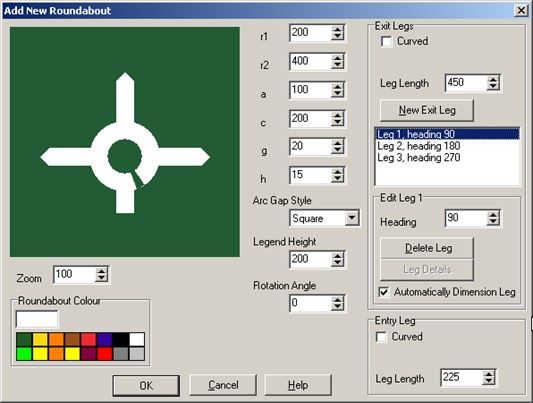
Traffic Sign Computer Aided Design (TraSiCAD V2.9.3), Transport and Main Roads, June 2020 18User manual Other functions to determine colours, rounded or pointed arrowheads and standardised long or short length shafts can be made in this option. A zoom function is also available to enhance the details in the design box. This function does not affect the zoom in the actual drawing. Note: Double clicking on any colour brings up a full colour palette as shown in Figure 2.6.7(b). Figure 2.6.7(b) – Full colour palette 2.6.8 Adding a Roundabout Symbol Note: The Add function can be activated in shortcut mode by placing the cursor somewhere on the active drawing and right-clicking the mouse. A dialogue box with four options, including Add, as previously shown in Figure 2.6.2(a), will appear on the drawing Various types and sizes of roundabouts can be added to a panel by selecting Roundabout Symbol in the Add to Panel X of Main Sign box and the ensuing Add New Roundabout dialogue box, as shown in Figure 2.6.8(a). Figure 2.6.8(a) – Roundabout Symbol Option: Add to Panel Various types and sizes of roundabouts can be designed in the Add New Roundabout dialogue box. Three sections are can be accessed through various boxes in each, where a number of options for specific designs can be entered, as detailed in Table 2.6.8. Traffic Sign Computer Aided Design (TraSiCAD V2.9.3), Transport and Main Roads, June 2020 19
User manual

     Dialogue box                                         Design option
        section
 View                     Zoom            Sets the screen view for optimum design detail.
                          Roundabout      Sets the symbol colour. Double clicking displays full colour
                          colour          palette.
                          r1              Inner roundabout radius
                          r2              Inner roundabout radius
                          a               Varies height of the triangular tip for selected arc gap styles.
                          c               Width of roundabout and legs.
                          g               Location in degrees of the arc gap.
                          h               Width of the arc gap in degrees.
                          Arc Gap         Sets as Square, Pointed or Double Pointed entry / exit.
                          Style
                          Legend          Sets the overall size of the symbol.
                          Height
                          Rotation        Sets the rotation angle of entire roundabout symbol (in
                          Angle           degrees).
 Exit Legs                Set the Exit legs to be straight or curved. By checking the Curved box, the
                          following options become available.
                          Curved left     When selected, the Exit's Curve installs for clockwise-driven
                                          roundabout as opposed to an anticlockwise-driven
                                          roundabout when unselected.
                          Attached at     Determines if the arc of a curved leg should be tangential to
                          Base            the roundabout body or tangential to centreline of the
                                          triangular tip of that leg.
                          Exit leg properties are also available
                          Leg Length      Determines the radial distance in millimetres, from the
                                          roundabout outer edge to the base of the Exit leg’s
                                          triangular tip.
                          New Exit        Inserts extra legs and indicates them in the associated list
                          Leg             box.
                          Selection of a particular leg in the list box enables the user to:
                               •   modify parts of exit legs
                               •   Delete or Add a selected leg, or
                               •   automatically size an exit leg via the Automatic Dimensioning
                                   Leg option.
                          If the Automatic Dimensioning Leg box is not checked when an exit leg
                          is selected, the leg can be 'manually' sized via the Leg Details box as
                          shown in Figure 2.6.8(b). This separate dialogue box individually tailors the
                          characteristics of that particular exit leg.

Traffic Sign Computer Aided Design (TraSiCAD V2.9.3), Transport and Main Roads, June 2020                20
User manual
Dialogue box Design option
section
Figure 2.6.8(b) – Manual sizing via Leg Details
Entry Leg Entry legs may be straight or curved. By checking the Curved box,
two options are made available.
Curved left Sets the exits to curve clockwise as opposed to the
default anticlockwise.
Attached at Determines the arc of a curved leg to be tangential to the
Base roundabout body or tangential to centreline of the
triangular tip of that leg.
Leg Length modification can also be achieved in this section.
Traffic Sign Computer Aided Design (TraSiCAD V2.9.3), Transport and Main Roads, June 2020 21User manual
2.6.9 Adding a Diagrammatic Direction Symbol
Note: The Add function can be activated in shortcut mode by placing the cursor somewhere on the active drawing
and right-clicking the mouse. A dialogue box with four options, including Add, as previously shown in
Figure 2.6.2(a), will appear on the drawing.
Various types and sizes of direction symbols can be added to a sign by selecting the Diagrammatic
Direction Symbol from the Add to Panel dialogue box, as shown in Figure 2.6.9.
Figure 2.6.9(a) – Diagrammatic Direction Symbol option: Add to Panel
Various types and sizes of diagrammatic direction symbols can be designed in the created Add New
Diagrammatic Direction Symbol dialogue box, shown in Figure 2.6.9(b).
Figure 2.6.9(b) – Add New Diagrammatic Direction Symbol option
When using diagrammatic direction symbols, three process areas are used to assist the design
• View section – actively views the design
• Base Branch Segments – selects and modifies curved or straight segments that when added
together, make up a particular branch, and
• Branches – adds, selects, and modifies branches to make up the basic design.
Traffic Sign Computer Aided Design (TraSiCAD V2.9.3), Transport and Main Roads, June 2020 22User manual
These process areas are detailed in Table 2.6.9.
Table 2.6.9 – Diagrammatic direction symbols process areas
Dialogue box Design options
section
View Zoom Assists in design view. Has no effect on the size of the
diagram in the drawing.
Rotation Angle Rotates the diagrammatical as required.
Legend Height Determines the size of the diagram on the panel.
Symbol Colour Sets the symbol colour.
Note: Double clicking on any colour brings up a full colour pallet
as shown in Figure 2.6.7(b).
Branches The default opening branch is tagged Segment S1 as shown in
Figure 2.6.9(b). This is in fact a pointed segment. As subsequent segments
are added (straight or curved), they are nominated a sequential number in the
Base Branch Segments box.
Base Branch The newest segment is allocated the Segment S1 notation (the notation for
Segments each existing segment increases as another new segment is added) as shown
in Figure 2.6.9(c).
Figure 2.6.9(c) – Base Branch Segments
Curve Left option allows a default right curve to be changed to left if required.
Note: Subsequent left curve segments require Curve Left selection each time.
Selecting a particular segment in the Base Branch Segments box activates
modifiers: Heading, Length, Width, Radius and Sweep to be altered as
required.
Add or remove segments by selecting the Add Line Segment, Add Curve
Segment or Delete Segment options.
Once a main Base Branch has been designed in the Base Branch Segments
box it may be necessary to overlay another branch on that design.
Selecting the Add Branch button produces another branch which is
superimposed on the preceding base branch. This is signified by Branch 1 in
the Branches box. The Base Branch Segments box now changes
designation to Branch 1 Segments box, indicating another S1 segment relating
to the new Branch 1, as shown in Figure 2.6.9(d).
Traffic Sign Computer Aided Design (TraSiCAD V2.9.3), Transport and Main Roads, June 2020 23User manual
Dialogue box Design options
section
Base Branch
Figure 2.6.9(d) – Add Branch option
Segments
(continued)
This S1 segment and possibly successive segments, although shown in the
box, exist on top of the base branch and may appear invisible. Only when
subsequent segments are added will they show their existence, as shown in
Figure 2.6.9(e).
Figure 2.6.9(e) – Depiction of multiple segments
When an added branch is selected the Edit Branch area reveals two further
options, as shown in Figure 2.6.9(f).
Figure 2.6.9(f) – Edit Branch option
Traffic Sign Computer Aided Design (TraSiCAD V2.9.3), Transport and Main Roads, June 2020 24User manual
Dialogue box Design options
section
Base Branch Heading Sets the direction in degrees to which a segment points.
Segments
Off Set Sets the amount of offset (distance) the segment is set vertically
(continued)
on the branch from the base of the diagrammatical.
As many new branches as required can be added to make up a detailed
represented drawing.
2.7 Viewing options
During the drawing process, TraSiCAD uses various viewing options to assist accurate sign detail and
design.
There are four options, as shown in Figure 2.7, which can be found in the View directory:
• Zoom
• Gridlines Setup
• Dimensions, and
• Sign Properties.
Figure 2.7 – View directory options
2.7.1 Zoom
The Zoom feature, shown in Figure 2.7.1, scales the drawing up or down on the screen to assist the
detailed designing of a sign.
Figure 2.7.1 – Zoom option
Traffic Sign Computer Aided Design (TraSiCAD V2.9.3), Transport and Main Roads, June 2020 25User manual Zoom levels range from 50% to 1000%. A Custom zoom range is also available and can be used to suit individualised viewing needs. 2.7.2 Gridlines Setup The Gridlines Setup, shown at Figure 2.7.2, enables a series of gridlines to be added to the drawing. This assists the particular spacing of items as each item is placed on the drawing. Figure 2.7.2 – Gridlines Setup option Any nominated grid size intervals up to a maximum of 1000 millimetres may be used. 2.7.2.1 Show Grid When selected, the Show Grid option enables the previously set grid to be visible on the screen for the drawing process, as shown in Figure 2.7.2.1. Figure 2.7.2.1 – Show Grid option 2.7.2.2 Snap to Grid When selected, the Snap to Grid option enables the items to be placed and 'snapped' onto the drawing along the previously determined grid pattern, as shown in Figure 2.7.2.2. 'Snapping' will occur even if the grid is not visible. Traffic Sign Computer Aided Design (TraSiCAD V2.9.3), Transport and Main Roads, June 2020 26
User manual

Figure 2.7.2.2 – Snap to Grid option

2.7.3    Dimension

Selecting the Dimension feature gives exact indications of the lengths, heights and clearances of
legends, symbols and images on a drawing. See Section 2.9.2.1 for details on removing arrow heads
for clearer detail.

As shown in Figure 2.7.3, in this mode, there are two separate areas on the screen drawing, showing:

    a) all horizontal and vertical dimensions associated with any items on that drawing, and

    b) a tabled view of all font legends, font types and sizes being used on all the panels and
         sub-signs within that drawing.

Figure 2.7.3 – Dimension option

Note: These dimensions actively vary as any drawing changes are being made.

2.7.4    Sign Properties

The Sign Properties option enables the user to navigate and modify colours, panels, plates, legends
and elements associated within the sign design. Figure 2.7.4 shows an example of the Sign
Properties option.
Note. The Properties box can be activated with Alt+P or by placing the cursor anywhere on the active drawing
and right-clicking the mouse. A dialogue box with four options appears, as shown in Figure 2.7.4. Select Sign
Properties.

Traffic Sign Computer Aided Design (TraSiCAD V2.9.3), Transport and Main Roads, June 2020                       27
User manual
Figure 2.7.4 – Sign Properties option example
This Properties box shows five separate tabs giving access to particular variables within the sign:
• Panels
• Legends
• Signs & Sub-Signs
• Images, and
• Guide Symbols.
2.7.4.1 Panels tab
As shown in Figure 2.7.4.1, selecting the Panels tab enables:
• accurate positioning of items within the sign
• sizing to particular dimensions
• splitting panels horizontally or vertically
• colour panels from the inherent panel colour (determined in Sign & Sub-signs tab) or from a
colour palette
• setting inherent border colours (checked), and
• individually setting and colouring of all borders if a panel is split (unchecked). Refer
Section 2.7.4.6 for details.
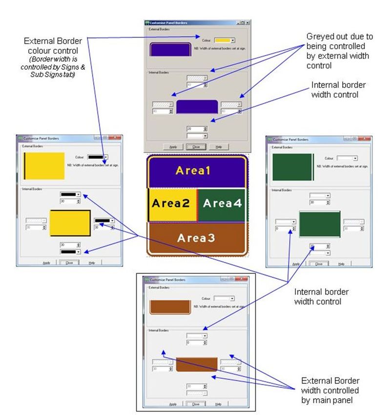
Traffic Sign Computer Aided Design (TraSiCAD V2.9.3), Transport and Main Roads, June 2020 28User manual
Figure 2.7.4.1 – Panels tab
2.7.4.2 Legend tab
As shown in Figure 2.7.4.2, selecting the Legend tab once a panel has been selected enables the
legend type to be:
• accurately positioned within the panel
• viewed,
• modified by height and type
• deleted
• specifically sized to a height
• automatically word width calculated, and
• coloured from a standard nine-colour palette.
Traffic Sign Computer Aided Design (TraSiCAD V2.9.3), Transport and Main Roads, June 2020 29User manual
Figure 2.7.4.2 – Legend tab
2.7.4.3 Images tab
As shown at Figure 2.7.4.3, the Images tab allows the selected image on a particular panel to be:
• accurately positioned within the panel
• identified
• sized to desired height or width
• stretched (non-proportionally) when checked, and
• deleted.
Figure 2.7.4.3 – Images tab
Traffic Sign Computer Aided Design (TraSiCAD V2.9.3), Transport and Main Roads, June 2020 30You can also read