REF-Hairdryer-C101-6ED user guide - Infineon Technologies
←
→
Page content transcription
If your browser does not render page correctly, please read the page content below

UG2020-16

 REF-Hairdryer-C101-6ED user guide
 SOI driver & Hairdryer application reference design kits

 About this document
 Scope and purpose
 This user guide provides an overview of the reference board REF-Hairdryer-C101-6ED including its main
 features, key test results and mechanical dimensions.
 The REF-Hairdryer-C101-6ED is a full-featured starter kit, turnkey motor drive designed for high-performance,
 high-efficiency PMSM/BLDC motor drive applications, including all of the required elements for hair dryer
 applications, such as IMC101T iMOTIONTM controller, IGBT and 6EDL04I06PT SOI three-phase gate driver.
 The starter kit features and demonstrates Infineon’s thin-film SOI technology and advanced motion control
 engine (MCE 2.0) technology for small power PMSM/BLDC motor drives up to 100 kRPM speed, and inverters up
 to a rating of 400 W. It is optimized for small home appliances like hairdryers, fans, pumps and other low-
 power motor drive applications.

 Intended audience
 This document is intended for all technical specialists who are familiar with high-speed motor control and
 middle/high voltage electronics converters. The reference design is intended to be used under laboratory
 conditions only by trained specialists.

 Reference Board
 Products embedded on a PCB, with focus on specific applications and defined use cases that can include
 Software. PCB and auxiliary circuits are optimized for the requirements of the target application.

 Note: Boards do not necessarily meet safety, EMI, quality standards (for example UL, CE) requirements.

 User guide Please read the Important notice and the Safety precautions and the Warnings
 www.infineon.com page 1 of 38 2020-11-02
REF-Hairdryer-C101-6ED user guide
SOI driver & Hairdryer application reference design kits
Important notice
Important notice
“Evaluation Boards and Reference Boards” shall mean products embedded on a printed circuit board
(PCB) for demonstration and/or evaluation purposes, which include, without limitation, demonstration,
reference and evaluation boards, kits and design (collectively referred to as “Reference Board”).

Environmental conditions have been considered in the design of the Evaluation Boards and Reference
Boards provided by Infineon Technologies. The design of the Evaluation Boards and Reference Boards
has been tested by Infineon Technologies only as described in this document. The design is not qualified
in terms of safety requirements, manufacturing and operation over the entire operating temperature
range or lifetime.

The Evaluation Boards and Reference Boards provided by Infineon Technologies are subject to functional
testing only under typical load conditions. Evaluation Boards and Reference Boards are not subject to the
same procedures as regular products regarding returned material analysis (RMA), process change
notification (PCN) and product discontinuation (PD).

Evaluation Boards and Reference Boards are not commercialized products, and are solely intended for
evaluation and testing purposes. In particular, they shall not be used for reliability testing or production.
The Evaluation Boards and Reference Boards may therefore not comply with CE or similar standards
(including but not limited to the EMC Directive 2004/EC/108 and the EMC Act) and may not fulfill other
requirements of the country in which they are operated by the customer. The customer shall ensure that
all Evaluation Boards and Reference Boards will be handled in a way which is compliant with the relevant
requirements and standards of the country in which they are operated.

The Evaluation Boards and Reference Boards as well as the information provided in this document are
addressed only to qualified and skilled technical staff, for laboratory usage, and shall be used and
managed according to the terms and conditions set forth in this document and in other related
documentation supplied with the respective Evaluation Board or Reference Board.

It is the responsibility of the customer’s technical departments to evaluate the suitability of the
Evaluation Boards and Reference Boards for the intended application, and to evaluate the completeness
and correctness of the information provided in this document with respect to such application.

The customer is obliged to ensure that the use of the Evaluation Boards and Reference Boards does not
cause any harm to persons or third party property.
The Evaluation Boards and Reference Boards and any information in this document is provided "as is"
and Infineon Technologies disclaims any warranties, express or implied, including but not limited to
warranties of non-infringement of third party rights and implied warranties of fitness for any purpose, or
for merchantability.

Infineon Technologies shall not be responsible for any damages resulting from the use of the Evaluation
Boards and Reference Boards and/or from any information provided in this document. The customer is
obliged to defend, indemnify and hold Infineon Technologies harmless from and against any claims or
damages arising out of or resulting from any use thereof.

Infineon Technologies reserves the right to modify this document and/or any information provided
herein at any time without further notice.

User guide 2 of 38
 2020-11-02
REF-Hairdryer-C101-6ED user guide
SOI driver & Hairdryer application reference design kits
Safety precautions
Safety precautions

Note: Please note the following warnings regarding the hazards associated with development systems.

Table 1 Safety precautions
 Warning: The DC link potential of this board is up to 310 VDC. When measuring voltage
 waveforms by oscilloscope, high voltage differential probes must be used. Failure to do
 so may result in personal injury or death.

 Warning: The reference board contains DC bus capacitors which take time to
 discharge after removal of the main supply. Before working on the drive system, wait
 five minutes for capacitors to discharge to safe voltage levels. Failure to do so may
 result in personal injury or death. Darkened display LEDs are not an indication that
 capacitors have discharged to safe voltage levels.
 Warning: The reference board is connected to the grid input during testing. Hence,
 high-voltage differential probes must be used when measuring voltage waveforms by
 oscilloscope. Failure to do so may result in personal injury or death. Darkened display
 LEDs are not an indication that capacitors have discharged to safe voltage levels.
 Warning: Remove or disconnect power from the drive before you disconnect or
 reconnect wires, or perform maintenance work. Wait five minutes after removing
 power to discharge the bus capacitors. Do not attempt to service the drive until the bus
 capacitors have discharged to zero. Failure to do so may result in personal injury or
 death.

 Caution: The heat sink and device surfaces of the reference board may become hot
 during testing. Hence, necessary precautions are required while handling the board.
 Failure to comply may cause injury.

 Caution: Only personnel familiar with the drive, power electronics and associated
 machinery should plan, install, commission and subsequently service the system.
 Failure to comply may result in personal injury and/or equipment damage.

 Caution: The reference board contains parts and assemblies sensitive to electrostatic
 discharge (ESD). Electrostatic control precautions are required when installing, testing,
 servicing or repairing the assembly. Component damage may result if ESD control
 procedures are not followed. If you are not familiar with electrostatic control
 procedures, refer to the applicable ESD protection handbooks and guidelines.
 Caution: A drive that is incorrectly applied or installed can lead to component damage
 or reduction in product lifetime. Wiring or application errors such as undersizing the
 motor, supplying an incorrect or inadequate AC supply, or excessive ambient
 temperatures may result in system malfunction.
 Caution: The reference board is shipped with packing materials that need to be
 removed prior to installation. Failure to remove all packing materials that are
 unnecessary for system installation may result in overheating or abnormal operating
 conditions.

User guide 3 of 38
 2020-11-02
REF-Hairdryer-C101-6ED user guide
SOI driver & Hairdryer application reference design kits
Table of contents

Table of contents
About this document ....................................................................................................................... 1
Important notice ............................................................................................................................ 2
Safety precautions.......................................................................................................................... 3
Table of contents ............................................................................................................................ 4
1 The board at a glance .............................................................................................................. 5
1.1 Delivery content ...................................................................................................................................... 5
1.2 Block diagram.......................................................................................................................................... 5
1.3 Main features ........................................................................................................................................... 8
1.4 Board parameters and technical data .................................................................................................... 8
2 System and functional description ..........................................................................................10
2.1 Getting started with REF-Hairdryer-C101-6ED ..................................................................................... 10
2.2 Description of the functional blocks..................................................................................................... 17
2.2.1 Overview of 6EDL04I06PT ................................................................................................................ 17
2.2.2 Overview of IMC101T........................................................................................................................ 18
2.2.3 Design tips for direct current sensing.............................................................................................. 19
2.2.4 Overcurrent protection and motor gatekill configuration ............................................................. 21
2.2.5 Design tips for negative transient voltage on VS pin (-VS) .............................................................. 24
3 System design.......................................................................................................................25
3.1 Schematics ............................................................................................................................................ 25
3.2 Layout .................................................................................................................................................... 29
3.3 Bill of material ....................................................................................................................................... 30
3.4 Connector details .................................................................................................................................. 31
4 System performance .............................................................................................................32
4.1 Thermal characterization...................................................................................................................... 32
4.2 Test results for over-temperature protection ...................................................................................... 33
5 References and appendices ....................................................................................................36
5.1 References ............................................................................................................................................. 36
5.2 Ordering information ............................................................................................................................ 36
Revision history.............................................................................................................................37

User guide 4 of 38
 2020-11-02
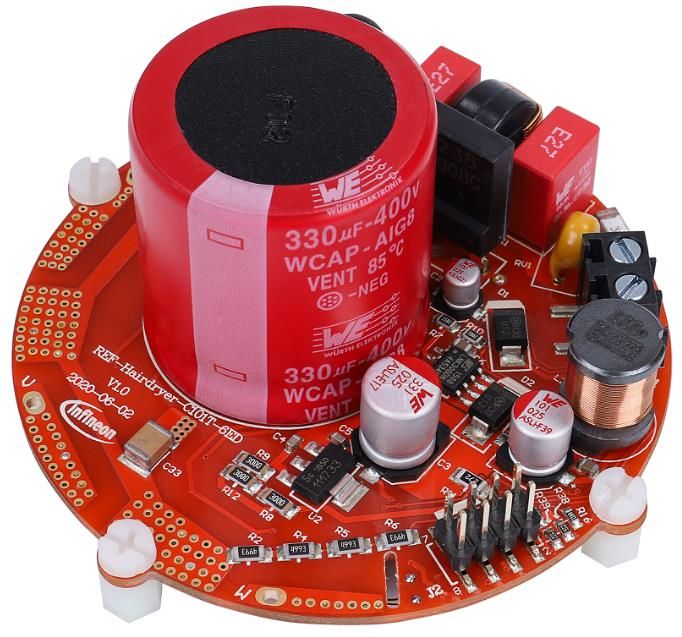
REF-Hairdryer-C101-6ED user guide
SOI driver & Hairdryer application reference design kits
The board at a glance

 1 The board at a glance
The REF-Hairdryer-C101-6ED is part of the SOI driver & iMOTION™ reference design kits. It is an optimized
design for 100 ~ 400 W power hairdryer applications, which can be used for different voltages or different power
classes, by replacing different IGBT, current-sensing resistors and by modifying DC bus capacitor. It allows fast
prototyping and fast time to market.
The REF-Hairdryer-C101-6ED reference design is available through regular Infineon distribution partners as well
as on Infineon's website. This document describes the main features of this board and provides information on
how to enable customers to copy, modify and qualify the design for production according to their own specific
requirements.

 1.1 Delivery content
The REF-Hairdryer-C101-6ED board is designed to provide ready-to-use, middle and high-voltage, middle and
high-speed motor drive solutions based on Infineon’s thin-film SOI technology, TRENCHSTOPTM Reverse
Conducting (RC) technology and advanced motion control engine (MCE 2.0) technology.
The delivery includes the finished board as shown in Figure 1 and Figure 2. It provides a single-phase AC
connector, an EMI filter, input rectifier, DC bus capacitors, iMOTION™ controller IMC101T, 6 A 600 V
TRENCHSTOPTM IGBT and 6EDL04I06PT three-phase gate driver with integrated bootstrap diode.
Environmental conditions were considered in the design of the REF-Hairdryer-C101-6ED, but the board is not
qualified in terms of safety requirements or manufacturing and operation over the entire operating
temperature range or lifetime. The boards provided by Infineon are subject to functional testing only.

 1.2 Block diagram
The block diagram of the REF-Hairdryer-C101-6ED is depicted in Figure 1.

 EMI Filter
 Power
 VAC &
 supply 15V 6ED SOI Gate
 Rectifier
 driver

 3.3V 3-phase
 inverter
 Host M
 Communication
 PWM
 Analog IMC101T

 Single Shunt Current sensing
 Isolated USB-to-
 UART Cable

Figure 1 Block diagram of the REF-Hairdryer-C101-6ED

User guide 5 of 38
 2020-11-02
REF-Hairdryer-C101-6ED user guide
SOI driver & Hairdryer application reference design kits
The board at a glance

Figure 2 points out the functional groups on the top side of the REF-Hairdryer-C101-6ED reference design.

 7

 6 1
 4

 3

 5 8

 2
 3
 6 3

 1. 85~265 VAC Input connector
 2. iMOTIONTM Link connector, UART 0 & UART1
 3. UVW Motor phase connector
 4. Bridge rectifier
 5. DC bus capacitor
 6. NTC
 7. EMI filter
 8. Auxiliary power supply

Figure 2 Functional groups of the REF-Hairdryer-C101-6ED reference design’s top side

User guide 6 of 38
 2020-11-02
REF-Hairdryer-C101-6ED user guide
SOI driver & Hairdryer application reference design kits
The board at a glance

Figure 3 points out the functional groups on the bottom side of the REF-Hairdryer-C101-6ED reference design.

 12 11

 13 14

 9
 10
 10
 11

 9. VSP speed potentiometer
 10. NTC sensor
 11. UVW inverter IGBTs
 12. IMC101T controller
 13. 6EDL04I06PT gate driver
 14. Shunt resistor
Figure 3 Functional groups of the bottom side of REF-Hairdryer-C101-6ED reference design

User guide 7 of 38
 2020-11-02
REF-Hairdryer-C101-6ED user guide SOI driver & Hairdryer application reference design kits The board at a glance 1.3 Main features The REF-Hairdryer-C101-6ED is a reference design for 100 ~ 240 Vac, 100 ~ 400 W motor drive applications, its characteristics include: • Input voltage 85 ~ 265 Vac • 400 W at 220 Vac input (with wind cooling) • On board EMI filter • Direct current sensing with single shunt • VSP speed command potentiometer • User UART for script function • Overcurrent and over temperature protection, fault diagnostic LED output • Auxiliary power supply with 15 V, 3.3 V • Round PCB in diameter of 70 mm, 2 layers, 1 oz. copper • RoHS compliant 1.4 Board parameters and technical data Table 2 depicts the key specifications of the reference design REF-Hairdryer-C101-6ED. Table 2 REF-Hairdryer-C101-6ED board specifications Parameter Symbol Conditions / comments Value Unit Input voltage Vac Optimized design for 220 VAC application 85 ~ 265 Vrms Maximum input current Iac(max) Input 220 VAC, Ta=25C, with 1 m/s wind cooling 3 Arms Maximum output power Pin(max1) Input 220 VAC, fPWM=16 kHz 2-ph PWM, Ta=25°C, TIGBT= 400 W 105 °C, with 1 m/s wind, 3X AD internal gain Pin(max2) Input 220 VAC, fPWM=16 kHz 2-ph PWM, Ta=25°C, TIGBT= 100 W 105 °C, self-cooling mode, 6X AD internal gain Maximum motor Imtr(max1) Input 220 VAC, fPWM=16 kHz 2-ph PWM, Ta=25°C, TIGBT= 1.5 Arms current 105 °C, with 1 m/s wind,3X AD internal gain Imtr(max2) 6X AD internal gain allows maximum 1.2A motor 0.6 Arms output peak current Maximum DC bus Vdc(max) DC bus capacitor is 400 V, 330µF 400 V voltage Minimum DC bus Vdc(min) Aux power supply brown-in voltage 40 V voltage Shunt Resistance Rsh Direct ADC sample (without external OPA) 250 mΩ Protections Motor current Itrip1 Wizard setup for OC trigger level, related to AD 3.6 1 Apeak protection trigger level range, shunt resistor RS1 and pull-up bias ( R17 & at AD internal 3X gain R20 ) 1 For iMOTION™ IC IMCxxx, there are three types of Gatekill input source options in MCEWizard setup: Gatekill-pin, Comparator and Both. If you select “comparator” mode, the external Gatekill signal will be not used, and the signal I_Shunt will be compared by the internal comparator with the “Device overcurrent trigger level setting” value set in MCEWizard. User guide 8 of 38 2020-11-02
REF-Hairdryer-C101-6ED user guide
SOI driver & Hairdryer application reference design kits
The board at a glance

 Parameter Symbol Conditions / comments Value Unit
 Motor current Itrip2 Wizard setup for OC trigger level, related to AD 1.2 Apeak
 protection trigger level range, shunt resistor RS1 and pull-up bias ( R17 &
 at AD internal 6X gain R20 )
 Motor current Itrip3 Hardware comparator overcurrent protection, 3.56 Apeak
 protection trigger level related to RS1 and 6EDL04I06PT’s Itrip threshold
 (445 mV typical).
 Thermal protection Tprotection Temperature gap between junction and NTC sensor 105 °C
 level needs to be considered

 Auxiliary power supply 1 – 15 V
 Output voltage Vout1 Used for IGBT gate driver 15 ± 2% V
 Maximum output Iout1 100 mA
 current

 Auxiliary power supply 2 – 3.3 V
 Output voltage Vout2 Used for IMC controller and protection circuits 3.3 ± 1% V
 Maximum output Iout2 100 mA
 current

 PCB characteristics
 Dimension Round diameter 70 mm
 Material FR4, 1.6 mm thickness, 1oz PCB

 System environment
 Ambient temperature Ta Non-condensing, maximum RH of 95% 0 ~ 50 °C

User guide 9 of 38
 2020-11-02
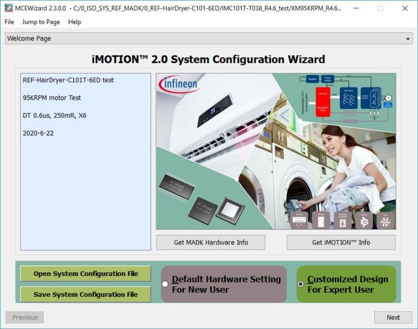
REF-Hairdryer-C101-6ED user guide
SOI driver & Hairdryer application reference design kits
System and functional description

 2 System and functional description
 2.1 Getting started with REF-Hairdryer-C101-6ED
The REF-Hairdryer-C101-6ED reference designs are shipped with embedded firmware and default parameters.
This chapter provides more details on setting up the system and getting started with the iMOTION™ development
platform. A 100 W 95000 RPM BLDC hairdryer motor and 400 W 2500 RPM PMSM motor are used for the default
DEMO function and thermal test. Please note that motor parameters need to be double-checked in MCEWizard if
a different motor is used.
iMOTIONTM Link or third-party isolated USB-to-UART cable is needed to bridge the PC/debugger side and motor
drive system (the target iMOTION™ device, hot side) with 1 kV DC galvanic isolation.
The iMOTION™ software tools, MCEDesigner and MCEWizard, are required to initially set up the system, as well
as to control and fine-tune the system performance to match the user’s exact needs. These tools are available
for download via the Infineon website (https://www.infineon.com/cms/en/product/power/motor-control-
ics/digital-motor-controller-imotion/imc101t-t038/#!tools). Please visit this page periodically to check for
tool/software updates.
After downloading and installing the iMOTION™ PC tools, MCEWizard and MCEDesigner, the following steps need
to be taken to run the motor. Please refer to MCEWizard and MCEDesigner documentation for more information.
Figure 4 shows the basic system connection using REF-Hairdryer-C101-6ED to run a hairdryer motor with
sensorless mode:

 VAC
 Input

 iMOTION Link Connector
 (USB-to-UART)

 Motor Phase
 Outputs

Figure 4 System connection example

User guide 10 of 38
 2020-11-02
REF-Hairdryer-C101-6ED user guide
SOI driver & Hairdryer application reference design kits
System and functional description

Figure 5 shows the MCEWizard welcome page and interface of MCEDesigner.

Figure 5 MCEWizard welcome page and MCEDesigner interface

User guide 11 of 38
 2020-11-02
REF-Hairdryer-C101-6ED user guide
SOI driver & Hairdryer application reference design kits
System and functional description

Here are the steps needed to run the motor:
1. Connect iMOTIONTM Link’s 8-pin cable to J2 with default pin order (Align connector orientation markings
 with PCB silkscreen markings), and connect PC-USB connector to iMOTIONTM Link.
2. Use MCEWizard to enter the target motor’s system and operating parameters, as well as evaluation board’s
 hardware parameters, which will then be used to calculate the digital parameter set of the controller
 representing the complete motor drive system.
3. After system and operating parameters are set, go to the “Verify & Save Page” and click on “Calculate
 Parameters” button. If no errors are reported, then save the drive parameter set into your project directory
 by clicking “Export to MCEDesigner file (.txt)” (Figure 6); if an error is detected, double-click on the error
 message (highlighted in RED) and adjust the related parameter. The saved drive system parameter file will be
 later used by the MCEDesigner in step 9.
 (Please refer to MCEWizard_V2.3.0.0 User Guide.pdf for more details, which is in MCE Wizard’s install path)

Figure 6 MCEWizard Verify and Save page

4. Connect 220 VAC power supply and UVW outputs to the motor.
5. Power on 220 VAC, LED1, LED2 & LED6 ON.
6. Start MCEDesigner tool and open MCEDesigner default configuration file (.irc) for IMC101T device
 (IMC101T_Vxxx.irc) by clicking “File” > “Open”.
 (IMC101T_Vxxx.irc file is included in downloaded “IMC101T MCE Software Package”)
7. MCEDesigner should automatically connect to the REF-Hairdryer-C101-6ED board using default COM port
 (Indicated by green circle next to “COMx Up” status in the bottom frame of the MCEDesigner GUI). If it cannot
 establish the connection due to incorrect COM port, change COM port by doing the following steps: click on

User guide 12 of 38
 2020-11-02
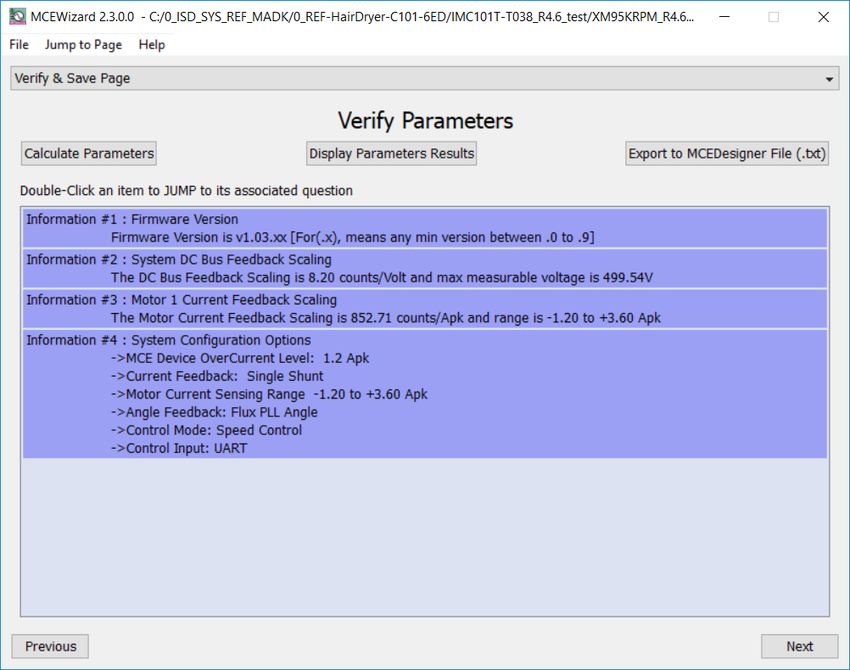
REF-Hairdryer-C101-6ED user guide
SOI driver & Hairdryer application reference design kits
System and functional description

 the “System Page” window and then click on “Preferences > Connection > Connect using,” and choose one of
 the other available COM ports from the drop-down list.

8. In case of blank IC: If the firmware has been erased from the IMC101T, a warning message will pop up saying
 “Target device firmware and parameters file are not programmed! Please program firmware and parameters
 file” (Figure 7). See step 9 on how to obtain/program firmware and parameters.

Figure 7 MCEDesigner warning message

9. In case of blank IC: Use the following steps to program the firmware and the parameters file into the internal
 Flash memory of iMOTION™ Control IC: Click on system page, click “Tools” > “Programmer” and select
 “Program Firmware and Parameters,” shown as Figure 8 below. The encrypted firmware is available in
 “IMC101T MCE Software Package,” regarding the parameters file, browse and select the .txt file in step 3.

 (If blank IMC101T IC, MCE Designer will pop up information “Target device firmware and parameter files are not
 programmed!”) Program the MCE firmware and system parameters into the internal Flash memory of iMOTION™ IC by
 clicking “Tools > Programmer “in the pull-down menu, and then clicking on the “Program Firmware and Parameter”
 check box. Select right Parameter file and firmware file. Finally click “Start” button to program firmware and parameter.
 Then click YES and then the OK button to update IRC file with parameter file; finally “Save As” the IRC file to your own file
 name that contains COM config, Parameters & firmware file path information. (Please refer to MCEDesigner User
 Guide.pdf and MCEDesigner_V2.3.0.0 Application Guide.pdf for more details, which is in MCE Designer’s install path)

 Red LED1 will flash on after the program is done.

Figure 8 MCEDesigner Program message

User guide 13 of 38
 2020-11-02
REF-Hairdryer-C101-6ED user guide
SOI driver & Hairdryer application reference design kits
System and functional description

10. Double click “VF Diagnostic” function in motor1 page, monitor motor current with oscilloscope. If motor
 current is not sinusoidal, change target speed and Vd_Ext in VF Diagnostic sub-function, then double-click
 “VF Diagnostic” until oscilloscope shows a steady sinusoidal current, with amplitude of 30~50% motor rate
 current.
 Double-click “Iu & Iv_Slow” in System page > Monitor Definitions, the motor current feedback would be very
 clean and sinusoidal, as shown in Figure 9, otherwise please tune “Gating Propagation Delay & Phase Shift
 Window Size” in MCE Wizard. The sampled motor current amplitude should be over 300 cts ~500 cts
 (corresponding to 30%~50% motor rate current); otherwise, motor current sample-related hardware and
 setup need tuning for better ADC range usage.
 The noise and spike in traced waveforms must be less than 50 cts, or below 5% of motor current; otherwise,
 motor current sample-related hardware and setup need tuning.

 “VF Diagnostic” sub function can verify:
 • If motor is correctly connected
 • If IGBT & gate driver work as expected
 • If current sensing related parameters are correctly configured
 • If PCB layout and DC bus decouple have been done correctly
 After “VF Diagnostic” is done, click STOP button (the red traffic light button) to stop PWM.
 Please note that motor shaft might only be vibrating during “VF Diagnostic”, which depends on target speed
 and Vd_Ext setup.

Figure 9 Trace waveform for Iu & Iv open-loop diagnostic

11. Start the motor by clicking the green traffic light button in the control bar (or double-click Start Motor sub
 function in Motor1 page, group of User Application Function Definitions); motor runs if above step goes well.

User guide 14 of 38
 2020-11-02
REF-Hairdryer-C101-6ED user guide
SOI driver & Hairdryer application reference design kits
System and functional description

12. Check motor spin direction, adjust UVW connection order or set negative target speed in MCE Designer if
 direction is wrong.

13. Set target speed to about 50% of speed, start “Iu & Flx_M” trace with “Auto Repeat On Level,” see Figure 10.
 Flx_M is better within the range of 2000~2500 (rated value is 2048), and MUST be steady and DC-like.

 Then set target speed to 100% of rate speed, re-do above trace. Flx_M should be steadier and closer to 2048,
 as shown in Figure 11.

Figure 10 Trace waveform for Iu & Flx-M at 50% speed

Figure 11 Trace waveform for Iu & Flx-M at rate speed

User guide 15 of 38
 2020-11-02
REF-Hairdryer-C101-6ED user guide
SOI driver & Hairdryer application reference design kits
System and functional description

 Some key tips for better motor-performance tuning:
 • If Flx_M is not steady (swinging or oscillating), double-check motor parameters, speed loop PI gain, flux Estimator
 time constant and PLL PI bandwidth (parameters PLLKp & PLLKi) related setup.
 • If Flx_M is very noisy, double check current feedback and Vdc-related hardware and parameters (need both trace
 waveform and oscilloscope waveform for the modification).

 • If Flx_M is far from 2048, “Motor Back EMF Constant (Ke)” needs to be adjusted in MCE Wizard.
 • If Flx_M is much difference at 50% and 100% speed (say, over 20%), motor parameters (L Q, LD and winding
 resistance) need double confirm, or this motor runs in high saturation region (especially for some ultra-low cost
 BLDC motor).

14. Once the firmware has been programmed, in case a new parameter file has to be programmed, follow the
 same instructions given in step 9. In this case, firmware programming is no longer needed, and it is possible
 to select the first option “Program Parameters.”

Note1: For detailed information on controller programming, refer to AN2018-33 iMOTION™ 2.0 Device
Programming, MCEDesigner documentation and MCEWizard documentation.

Note2: This user guide use “Using Count Value Tune” setup for the MCE Designer trace, which shows original MCE
internal data. MCEDesigner’s trace default setup is “Using Real Value Tune”.
Please check the setup with below operation: Click System page > Preferences > Tuning value Format

User guide 16 of 38
 2020-11-02
REF-Hairdryer-C101-6ED user guide
SOI driver & Hairdryer application reference design kits
System and functional description

 2.2 Description of the functional blocks
The motor inverter of REF-Hairdryer-C101-6ED reference design is implemented by the 6EDL04I06PT driver and
IKD06N60RF RCD IGBT. IMC101T is used for motor control, and motor current sensing is direct AD sensing with
single shunt mode.

 2.2.1 Overview of 6EDL04I06PT

Figure 12 illustrates the internal block diagram of the 6EDL04I06PT, whose PWM input signal is high true.

 BIAS NETWORK / VDD2 BOOTSTRAP DIODE-VB1

 INPUT NOISE BIAS NETWORK - VB1
 VB1
 HIN1 FILTER DEADTIME & LATCH
 SHOOT-THROUGH Gate-
 z HV LEVEL-SHIFTER COMPAR
 PREVENTION
 + REVERSE-DIODE ATOR UV- Drive HO1
 DETECT

 INPUT NOISE VS1
 LIN1 FILTER

 BOOTSTRAP DIODE-VB2

 INPUT NOISE
 BIAS NETWORK - VB2
 VB2
 HIN2 FILTER DEADTIME &
 LATCH
 SHOOT-THROUGH
 HV LEVEL-SHIFTER COMPAR Gate-
 PREVENTION HO2
 + REVERSE-DIODE ATOR UV- Drive
 DETECT

 INPUT NOISE VS2
 LIN2 FILTER

 BOOTSTRAP DIODE-VB3
 INPUT NOISE
 HIN3 FILTER DEADTIME & BIAS NETWORK / VB3
 VB3
 SHOOT-THROUGH LATCH
 PREVENTION HV LEVEL-SHIFTER COMPAR Gate-
 + REVERSE-DIODE ATOR UV- Drive HO3
 DETECT
 INPUT NOISE
 LIN3 FILTER VS3

 >1

 INPUT NOISE
 UV-
 VCC
 EN FILTER
 DETECT

 VSS / COM Gate-
 DELAY LEVEL- Drive LO1
 SHIFTER

 ITRIP INPUT NOISE
 FILTER VSS / COM Gate-
 DELAY LEVEL- Drive LO2
 SHIFTER
 VDD2 S Q
 SET
 DOMINANT
 IRCIN VSS / COM
 LATCH Gate-
 RCIN R DELAY LEVEL- Drive LO3
 SHIFTER

 COM

 FAULT
 VSS
 >1

Figure 12 Block diagram of 6EDL04I06PT

User guide 17 of 38
 2020-11-02
REF-Hairdryer-C101-6ED user guide SOI driver & Hairdryer application reference design kits System and functional description 6EDL04I06PT is DSO-28 package; the pin definition is the same as IRS2136 except for the active logic, as shown in Figure 13. Figure 13 6EDL04I06PT lead assignments PG-DSO-28 (top view) Main features of SOI three-phase gate driver 6EDL04I06PT include: • Infineon thin-film SOI technology • Fully operational to +600 V, floating channel designed for bootstrap operation • Output peak source/sink current capability +240 mA/-420 mA • Integrated ultra-fast, low RDS(ON) bootstrap diode • Separate control circuits for six drivers • Tolerant to negative transient voltage up to -50 V • Overcurrent protection with 445 mV (+/-15 % tolerance) reference threshold • Externally programmable delay for fault clear after overcurrent detection • Shut down of all switches during error conditions • 3.3 V, 5 V and 15 V input logic compatible • Signal interlocking of every phase to prevent cross-conduction, Internal dead time 310 ns (typical) • Intergrate input filter, no external filters needed to reduce noise sensitivity • RoHS compliant 2.2.2 Overview of IMC101T IMC101T is a member of iMOTION™ high performance motor control IC, whose main features include: Motion control engine as ready-to-use controller solution for sensorless and Hall-sensor motor drives Field-oriented control (FOC) for permanent magnet synchronous motor (PMSM/BLDC) Optional support for Hall sensors (analog or digital) Space vector PWM with sinusoidal commutation and integrated protection features Current sensing via single shunt or leg shunt Integrated analog comparators for overcurrent protection User guide 18 of 38 2020-11-02
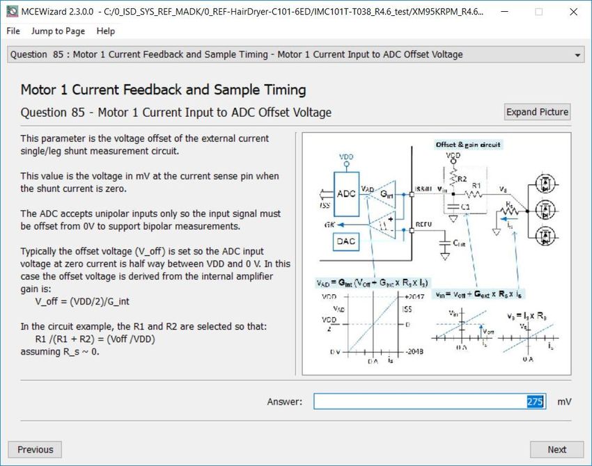
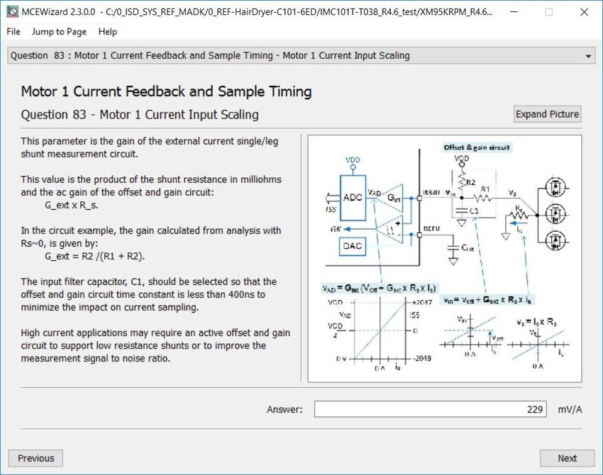
REF-Hairdryer-C101-6ED user guide SOI driver & Hairdryer application reference design kits System and functional description Integrated scripting engine for application flexibility 3.3 V or 5.0 V supply voltage options for controller Flexible host interface options for speed commands: UART, SPI, PWM or analog signal Class B pre-certification (IEC60335) for MCE2.0 firmware 2.2.3 Design tips for direct current sensing From the point view of the AD convertor, the current input scaling value is the product of the shunt resistance in milliohms and gain of external current sense amplifier for motor control design, as shown in Figure 14. Figure 14 Current feedback scaling outside IMC101T Direct AD sample is used in the REF-Hairdryer-C101-6ED reference design, since hairdryers are cost-sensitive applications, which means, they are without external op-amp, only RC for operational gain & bias (R17 & R20), and low pass filter (R19 & C21), as shown in Figure 15. Figure 15 Direct AD sample (current feedback without external op-amp) R19 & C21 is a low pass filter for switching noise suppression, whose time constant is about 0.1~0.5 µs normally. The real AD input voltage is decided by the divider of R17 & R20, with bias of 275 mV and gain of 0.916: User guide 19 of 38 2020-11-02
REF-Hairdryer-C101-6ED user guide
SOI driver & Hairdryer application reference design kits
System and functional description

 17 1.1
 = 1 ∗ = ∗ = 0.916 ∗ 1 ∗
 17 + 20 1.1 + 0.1 1

A 250 mOhm 2W 2512 package single shunt resistor and 1.1 k & 100 Ohm pull-up net is the default configuration
for the REF-Hairdryer-C101-6ED reference design, which means 1A DC bus current produces 229 mV voltage to
ADC input, MCE Wizard’s “Motor1 Current Input Scaling” needs input as 229 mV/A (250*0.916=229).
Please note that Internal Current Feedback Amplifier Gain (Question 88 for MCEWizard V2.3.0.0) is ADC’s
internal gain, which defines the MAX ADC input range to VCC/Gain. For 3.3 V power supply, the ADC sensing
range is 0~1.1 V if 3X internal gain is selected, and 0~550 mV if 6X internal gain is selected, 0~275 mV if 12X
internal gain is selected.

R17 & R20 also determine the ADC operational bias for current sensing, which corresponds to the motor
regeneration operation range. For those applications that only work in motoring mode, the bias can be as low
as possible to reserve enough ADC range for the motoring mode, since negative input would not occur.

Figure 16 Current feedback configuration in MCEWizard

User guide 20 of 38
 2020-11-02
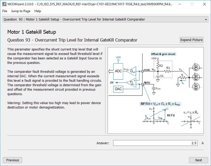
REF-Hairdryer-C101-6ED user guide SOI driver & Hairdryer application reference design kits System and functional description Please note the following two design guidelines for direct AD sample: The external RC network’s input gain is less than 1. Normally ADC internal gain needs to be configured to X3, X6 or X12 to lower the required input signal range, and reduce shunt resistor power dissipation. RS1 must be much higher than 10 mOhm to achieve enough current sensing signal-to-noise ratio (SNR) and improve control performance: For example, to achieve sufficiently high SNR, motor current sensing counts need be over 30~50% of AD range (traced Iu peak over 600 cts~1000 cts) at rate motor current, and PCB ground noise lower than 5% of total sampled signal in MCEDesigner trace result. Very low SNR might cause the motor start to fail, or not running smoothly at low power. There is NO common-mode noise-rejection ability, compared to external op-amp sample mode. Direct AD current-sensing mode needs to deal with the PCB GND network very carefully to reduce grounding noise as much as possible, to make shunt resisters as close as possible to IMC101T IC and DC bus capacitor. Please note that any voltage difference between IMC101T’s ADC ground and shunt resistor ground will be considered as an “input signal” and will deteriorate control performance or increase motor audible noise. 2.2.4 Overcurrent protection and motor gatekill configuration Figure 17 displays the overcurrent protection circuit for the IMC101T application. R17 & R20 sensed voltage is connected to ADC and internal comparators to achieve the overcurrent protection function. Only internal comparators are used for overcurrent protection. The reference of the internal comparators is set by IMC101T’s internal DAC (Sigma delta DAC, stream output), and external C23 is the low pass filter capacitor. MCEWizard calculates the DAC reference voltage based on the question input of “Device Overcurrent trigger level setting for Comparator” and “Motor1 Current Input to ADC Offset Voltage.” MCEWizard’s output parameter CompRef defines the DAC output voltage, which depends on the 3 items listed below, and shown in Figure 18 ~ Figure 20: A: Expected OC threshold B: Gain of external current sensing network C: Offset of the external op-amp or RC divider Figure 17 Overcurrent protection circuit on the REF-Hairdryer-C101-6ED reference design User guide 21 of 38 2020-11-02
REF-Hairdryer-C101-6ED user guide
SOI driver & Hairdryer application reference design kits
System and functional description

Figure 18 Overcurrent protection trigger level setup in MCEWizard

Figure 19 Offset setup in MCEWizard

User guide 22 of 38
 2020-11-02
REF-Hairdryer-C101-6ED user guide
SOI driver & Hairdryer application reference design kits
System and functional description

Figure 20 Gatekill input source setup in MCEWizard

Normally, it is recommended to set a value higher than the motor’s maximum peak current (maximum RMS
current * 1.414) in “Overcurrent Trip Level for Internal Gatekill Comparator”, with a reserve of at least 30%
margin, especially for low impedance motors, of which peak sawtooth current would trigger unwanted
overcurrent fault (fake GK fault).

User guide 23 of 38
 2020-11-02
REF-Hairdryer-C101-6ED user guide
SOI driver & Hairdryer application reference design kits
System and functional description

 2.2.5 Design tips for negative transient voltage on VS pin (-VS)
A common problem in today’s power switching converters is the transient response of the switch node’s
voltage, as the power switches transition on and off quickly while carrying a large current, as illustrated in
Figure 21.

 Negative VS
Figure 21 Negative VS spike

This negative VS voltage can cause the high side output to change state, or the device to latch up resulting in
large currents or IQCC shifts. A high side output transition from high to low will not damage the IC or the switch,
however, a high side output transition from low to high when the low side is on can cause switch damage or
unreliable motor operation.
Negative VS excursions occur during faster switching events over long PCB traces or wiring harnesses that form
a parasitic inductor. The higher the parasitic inductor value and switching frequency, the larger is the potential
negative VS voltage that is developed during a switching event.
Negative VS immunity is a key determining factor in selecting a robust gate driver IC that will be more immune
to negative VS excursions due to inductive parasitic on the PCB or wiring harness.
In a typical motor drive system, dV/dt is typically designed to be in the range of 3-5 V/ns. The negative transient
voltage can exceed this range during some events such as short-circuit and overcurrent shutdown, when di/dt is
greater than in normal operation.
6EDL04I06PT has been designed for the robustness required in many of today’s demanding applications. An
indication of the robustness of 6EDL04I06PT can be seen in datasheet electrical parameters that shows a -50 V
500 ns immunity for negative transients on VS node.
Even though the 6EDL04I06PT has been shown to be able to handle these large, negative transient voltage
conditions, it is highly recommended that the circuit designer always limit the negative transient voltage on the
VS pin as much as possible by careful PCB layout and component use.

User guide 24 of 38
 2020-11-02
REF-Hairdryer-C101-6ED user guide
SOI driver & Hairdryer application reference design kits
System design

 3 System design
The REF-Hairdryer-C101-6ED reference design is an optimized design for 220 V small home appliances like
hairdryers. To meet individual customer requirements and to make the REF-Hairdryer-C101-6ED board a basis
for development or modification, all board design data such as schematics, Gerber and Altium design data can
be found on the Infineon homepage.

 3.1 Schematics
The overall schematic diagram for the IMC101T controller is provided in Figure 22.

Figure 22 Schematics for REF-Hairdryer-C101-6ED: IMC101T controller

User guide 25 of 38
 2020-11-02
REF-Hairdryer-C101-6ED user guide
SOI driver & Hairdryer application reference design kits
System design

Figure 23 depicts the schematic of the auxiliary power supply for the REF-Hairdryer-C101-6ED board. A high
voltage buck DC-DC for 15 V and one linear LDO used for 3.3 V power supply.

Figure 23 Power supply section of the REF-Hairdryer-C101-6ED reference design

The inverter section is implemented using 6EDL04I06PT plus IKD06N60RF as sketched in Figure 24.
6EDL04I06PT driver ability is source current +0.24 A and sink current -0.42 A; R24 & R32 are the gate resistors to
control the U phase IGBT’s ON time, and R24 & R32 together with R23 & R29 to set the OFF time.

Figure 24 Inverter section on REF-Hairdryer-C101-6ED

The recommended dead time is 400~800 ns for MCEWizard setup, which represents a real ON/OFF time of
100~300 ns, as shown in Figure 25 and Figure 26 (CH1: UGE for low side IGBT, CH3: motor current, CH4: UGE for
high side IGBT).
Note: The gate resistors and dead time setup need adjusting if new IGBTs are used, since different IGBT have
different Qg.

User guide 26 of 38
 2020-11-02
REF-Hairdryer-C101-6ED user guide
SOI driver & Hairdryer application reference design kits
System design

Figure 25 ON-time test waveform

Figure 26 OFF-time test waveform

User guide 27 of 38
 2020-11-02
REF-Hairdryer-C101-6ED user guide
SOI driver & Hairdryer application reference design kits
System design

Figure 27 provides the DC bus sense resistor details on the REF-Hairdryer-C101-6ED reference design.
The high-side resistor is 2000 kOhm (R2+R4+R5+R6) and low side resistor is 13.3 kΩ (R14), 0 ~ 499.5 V DCBUS
reflecting 0 ~ 3.3 V at the ADC input pin with 3.3 V power supply.

Figure 27 DC bus sense resistor on REF-Hairdryer-C101-6ED reference design

For a wider DC sensing range, R14 can be adjusted to a lower value; the hardware changes should be configured
in MCEWizard, as shown in Figure 28.

Figure 28 DC bus sensing configuration in MCEWizard

The Vdc sensing low-pass filter time constant is (R2~R6//R14)*C15 = (2000 k//13.3 k)*10 nF =132 µs , which is at
least two times the 16 kHz PWM periods (66 µs); C15 can be adjusted to higher capacitance for clean Vdc
sensing, if new motor and new IGBT cause Vdc bus sensing noise at MCEDesigner trace.

User guide 28 of 38
 2020-11-02
REF-Hairdryer-C101-6ED user guide
SOI driver & Hairdryer application reference design kits
System design

 3.2 Layout
This board has two electrical layers with 35 µm copper (standard). Its main part size is round 70 mm, maximum
76 mm with mounting hole, which can be put inside the hairdryer, to use the air flow to cooling this board. The
PCB board thickness is 1.6 mm.
Figure 29 illustrates the top and bottom assembly print of the reference design.

Figure 29 Top and bottom assembly print of the REF-Hairdryer-C101-6ED reference design

The top and bottom layer routing of the PCB is provided in Figure 30 .

Figure 30 Top and bottom layer routing of the REF-Hairdryer-C101-6ED

User guide 29 of 38
 2020-11-02
REF-Hairdryer-C101-6ED user guide
SOI driver & Hairdryer application reference design kits
System design

 3.3 Bill of material
Table 3 shows the major parts of the REF-Hairdryer-C101-6ED. The complete bill of material is available on the
download section of the Infineon homepage. A log-in is required to download this material.

Table 3 BOM of the most important/critical parts of the evaluation or reference board
S. Manufacturer
 Ref Designator Description Manufacturer P/N
No.
1 BR1 BRIDGE RECT, 800V 4A KBJ408G
 Aluminum Electrolytic Capacitors, 400V
2 C1 DC, 330uF 861011385023 Wurth Elektronik
3 F1 FUSE, 3A 250VAC, SMD 0443003.DR
4 J1 5.00 mm Horizontal Entry SMT, 2 pin 691709710302 Wurth Elektronik
 SMT, pitch 2.54mm, Dual Row, Vertical,
5 J2 8pin 61000821121 Wurth Elektronik
 Common Mode Power Line Choke, 0.5mH,
6 L1 3.5A, 250V 7448013501 Wurth Elektronik
7 L2 Inductor, size 1014, 2200 uH, 0.48 A 7447480222 Wurth Elektronik
 THERMISTOR NTC 10KOHM 3936K NXFT15WB473FA2B0
8 NTC1 BEAD 60
 Q1, Q2, Q3, Q4, Infineon
9 Q5, Q6 600V TRENCHSTOP, RC IGBT IKD06N60RF Technologies
10 RT1 ICL 5 OHM 20% 5A 15MM B57237S0509M000
 WE-VD Disk Varistor, size 5mm, 385Vrms,
11 RV1 505Vdc 820453811 Wurth Elektronik
12 U1 DC_DC IC, SO8 LNK306DG-TL
 IFX1117MEV33HTMA Infineon
13 1 Technologies
 U2 IC REG LINEAR 3.3V 1A SOT223-4
 Infineon
14 U3 IMC101T-T038 Technologies
 Infineon
15 U4 GATE DRVR IC DSO28 6EDL04I06PTXUMA1 Technologies
16 VR1 TRIMMER 10K OHM 0.125W ST32ETB103

User guide 30 of 38
 2020-11-02
REF-Hairdryer-C101-6ED user guide
SOI driver & Hairdryer application reference design kits
System design

 3.4 Connector details
General information about the connectors of the REF-Hairdryer-C101-6ED reference design is provided in this
section.
Table 4 includes the details of the AC input connector.

Table 4 AC input connector
 Pin Details
 J1 (1) AC L input
 J1 (2) AC N input

Table 5 denotes the details of the UART-related connector (iMOTIONTM Link connector J2)

Table 5 J2- iMOTIONTM link connector
 S. No. Pin Details
 1 TXD1 User UART for script communication
 2 RXD1 User UART for script communication
 3&6 +3.3 V On board 3.3 V supply
 4&5 GND Ground
 7 RXD0 MCE Designer & firmware download
 8 TXD0 MCE Designer & firmware download

Table 6 provides the details of the motor UVW output connector

Table 6 Motor side connector
 S. No. Pin Details
 U U Connected to motor phase U
 V V Connected to motor phase V
 W W Connected to motor phase W

User guide 31 of 38
 2020-11-02
REF-Hairdryer-C101-6ED user guide
SOI driver & Hairdryer application reference design kits
System performance

 4 System performance
 4.1 Thermal characterization
Figure 31 shows the thermal characterizations of REF-Hairdryer-C101-6ED at natural cooling conditions. The
tests reported have been performed under the following conditions: Tamb=25°C, VAC = 220 V, different phase
current values until the IGBT case reaches 105°C, four PWM frequencies (6, 8, 16 and 24 kHz) tested, 3-phase
modulation mode and 2-phase modulation.

 1200
 Max output current Vs PWM frequency
 1000
 2ph-PWM
 3ph-PWM
 Output Current (mA)

 800

 600

 400

 200
 PWM frequency (kHz)
 0
 0 5 10 15 20 25 30

Figure 31 REF-Hairdryer-C101-6ED thermal characterization at nature cooling mode

Figure 32 shows the output ability at different cooling conditions, which are performed under the following
conditions: 16 KHz PWM, Tamb=25°C, VAC = 220 V, different input power until the IGBT case reaches 105°C.

 Tc vs input power
 16kHz, 2phase PWM
 120.00

 100.00

 80.00
 Tc (℃)

 60.00

 1m/s cooling nature cooling
 40.00

 20.00
 Input power(W)
 0.00
 0 50 100 150 200 250 300 350 400 450 500

Figure 32 Output ability at different cooling modes

User guide 32 of 38
 2020-11-02
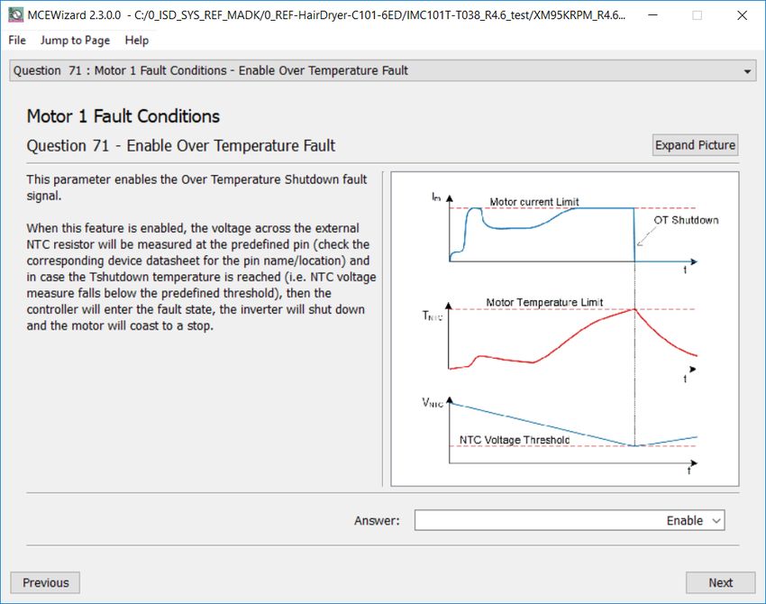
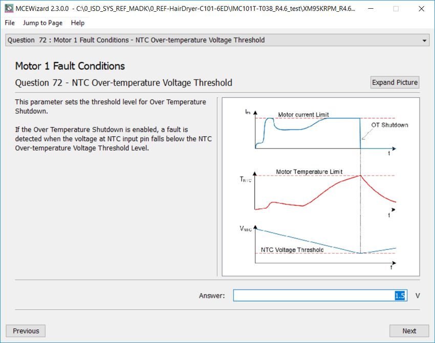
REF-Hairdryer-C101-6ED user guide
SOI driver & Hairdryer application reference design kits
System performance

 4.2 Test results for over-temperature protection
IMC101T’s firmware has overheat protection, Pin7 is the dedicated input of NTC temperature sensing. An
external NTC thermistor is attached on the Q6.
To activate over-temperature protection, 2 setups in MCEWizard as shown in Figure 33 and Figure 35 are
needed:
- Enable over-temperature shutdown function
- Set voltage for shutdown, consider the temperature difference between MOS and NTC

Figure 33 Over-temperature protection enabled in MCEWizard

User guide 33 of 38
 2020-11-02
REF-Hairdryer-C101-6ED user guide
SOI driver & Hairdryer application reference design kits
System performance

The NXFT15WB473FA2B thermistor’s B-constant is 4050 K, typical resistance and output of temperature-
sensing voltage listed in Table 7.

Table 7 NTC – Thermistor Characteristics
 Temperature Resistance Vout
 ( ℃) (kOhm) (mV)
 25 47 3000
 50 16.43 2566
 60 11.22 2326
 70 7.818 2061
 80 5.548 1787
 90 4.004 1518
 100 2.936 1269
 110 2.184 1047
 120 1.646 856
 125 1.436 772

The pull-up resistor is 4.7 kOhm, and IMC101T’s temperature-related AD input voltage is shown in Figure 34.
 3250
 3000
 2750
 NTC Output
 2500
 2250
 Voltage to AD (mV)

 2000
 1750
 1500
 1250
 1000
 750
 500
 250
 0
 0 20 40 60 80 100 120 140
 Temperature ( ℃ )

Figure 34 NTC circuit and output voltage curve

User guide 34 of 38
 2020-11-02
REF-Hairdryer-C101-6ED user guide
SOI driver & Hairdryer application reference design kits
System performance

External NTC temperature shutdown value can be calculated as shown below and configured in MCEWizard as
shown in Figure 35. MCEWizard default setup is 1.5 V, which sets the NTC shutdown temperature to about
90 °C.

Figure 35 NTC shutdown temperature setup in MCEWizard

User guide 35 of 38
 2020-11-02
REF-Hairdryer-C101-6ED user guide
SOI driver & Hairdryer application reference design kits
References and appendices

 5 References and appendices
 5.1 References
[1] Datasheet of Infineon 6EDL04I06PT
[2] Datasheet of Infineon IMC101T
[3] Datasheet of IKD06N60RF
[4] MCEWizard User Guide
[5] MCEDesigner User Guide
[6] Infineon-MCESW-RM-User Manual

 5.2 Ordering information
 Base Part Number Package Standard Pack Orderable Part Number
 Form Quantity
REF-Hairdryer-C101-6ED EVAL Boxed 1 REFHairDryerC1016ED
IMC101T-T038 PG-TSSOP-38-9 Tape and Reel 3000 IMC101TT038XUMA1
IKD06N60RF PG-TO252-3 Tape and Reel 2500 IKD06N60RFATMA1
6EDL04I06PT PG-DSO-28 Tape and Reel 1000 6EDL04I06PTXUMA1

User guide 36 of 38
 2020-11-02
REF-Hairdryer-C101-6ED user guide
SOI driver & Hairdryer application reference design kits
Revision history

Revision history

 Document Date of release Description of changes
 version
 1.0 2020-7-20 First release
 1.1 2020-11-2 New UG template

User guide 37 of 38
 2020-11-02
Trademarks
All referenced product or service names and trademarks are the property of their respective owners.

 For further information on the product, technology,
Edition 2020-11-02 delivery terms and conditions and prices please
 Published by contact your nearest Infineon Technologies office
 (www.infineon.com).
 Infineon Technologies AG
 81726 Munich, Germany WARNINGS
 Due to technical requirements products may contain
 dangerous substances. For information on the types
 in question please contact your nearest Infineon
 © 2020 Infineon Technologies AG. Technologies office.
 All Rights Reserved.
 Except as otherwise explicitly approved by Infineon
 Do you have a question about this Technologies in a written document signed by
 authorized representatives of Infineon
 document? Technologies, Infineon Technologies’ products may
 Email: erratum@infineon.com not be used in any applications where a failure of the
 product or any consequences of the use thereof can
 reasonably be expected to result in personal injury.
 Document reference
 UG2020-16
You can also read