EVAL-M1-IM535 user guide - Infineon Technologies
←
→
Page content transcription
If your browser does not render page correctly, please read the page content below
UG2020-29

 EVAL-M1-IM535 user guide
 iMOTION™ modular application design kit

 About this document
 Scope and purpose
 This user guide provides an overview of the evaluation board EVAL-M1-IM535 including its main features, key
 data, pin assignments and mechanical dimensions.
 The EVAL-M1-IM535 is an evaluation board for motor drive applications, as part of the iMOTION™ modular
 application design kit. In combination with the control board equipped with the M1 20-pin interface connector
 such as EVAL-M1-101T, it features and demonstrates Infineon’s CIPOS™ Mini IPM technology and advanced
 motion control engine (MCE 2.0) technology for permanent magnet motors drive.
 The IM535-U6D CIPOS™ Mini IPM has 600 V of voltage and 30 A of current rating. It is optimized for major home
 appliances like air conditioners, pumps, fans and other low & middle power motor drive applications.
 This evaluation board EVAL-M1-IM535 is developed to support customers during their first steps designing
 applications with CIPOS™ Mini IPM IM535-U6D and running any permanent magnet motor via sensorless
 sinusoidal control.

 Intended audience
 This user guide is intended for all technical specialists who know motor control, middle- and low-power
 electronics converters. The board is intended to be used under laboratory conditions.

 Evaluation Board
 This board will be used during design-in, for evaluation and measurement of characteristics, and proof of data
 sheet specifications.

 Note: PCB and auxiliary circuits are NOT optimized for final customer design.

 Please read the Important notice and the Safety precautions and the Warnings V1.0
 www.infineon.com page 1 of 39 2020-09-30
EVAL-M1-IM535 user guide
iMOTION™ modular application design kit
Important notice
Important notice
“Evaluation Boards and Reference Boards” shall mean products embedded on a printed circuit board
(PCB) for demonstration and/or evaluation purposes, which include, without limitation, demonstration,
reference and evaluation boards, kits and design (collectively referred to as “Reference Board”).

Environmental conditions have been considered in the design of the Evaluation Boards and Reference
Boards provided by Infineon Technologies. The design of the Evaluation Boards and Reference Boards
has been tested by Infineon Technologies only as described in this document. The design is not qualified
in terms of safety requirements, manufacturing and operation over the entire operating temperature
range or lifetime.

The Evaluation Boards and Reference Boards provided by Infineon Technologies are subject to functional
testing only under typical load conditions. Evaluation Boards and Reference Boards are not subject to the
same procedures as regular products regarding returned material analysis (RMA), process change
notification (PCN) and product discontinuation (PD).

Evaluation Boards and Reference Boards are not commercialized products, and are solely intended for
evaluation and testing purposes. In particular, they shall not be used for reliability testing or production.
The Evaluation Boards and Reference Boards may therefore not comply with CE or similar standards
(including but not limited to the EMC Directive 2004/EC/108 and the EMC Act) and may not fulfill other
requirements of the country in which they are operated by the customer. The customer shall ensure that
all Evaluation Boards and Reference Boards will be handled in a way which is compliant with the relevant
requirements and standards of the country in which they are operated.

The Evaluation Boards and Reference Boards as well as the information provided in this document are
addressed only to qualified and skilled technical staff, for laboratory usage, and shall be used and
managed according to the terms and conditions set forth in this document and in other related
documentation supplied with the respective Evaluation Board or Reference Board.

It is the responsibility of the customer’s technical departments to evaluate the suitability of the
Evaluation Boards and Reference Boards for the intended application, and to evaluate the completeness
and correctness of the information provided in this document with respect to such application.

The customer is obliged to ensure that the use of the Evaluation Boards and Reference Boards does not
cause any harm to persons or third party property.
The Evaluation Boards and Reference Boards and any information in this document is provided "as is"
and Infineon Technologies disclaims any warranties, express or implied, including but not limited to
warranties of non-infringement of third party rights and implied warranties of fitness for any purpose, or
for merchantability.

Infineon Technologies shall not be responsible for any damages resulting from the use of the Evaluation
Boards and Reference Boards and/or from any information provided in this document. The customer is
obliged to defend, indemnify and hold Infineon Technologies harmless from and against any claims or
damages arising out of or resulting from any use thereof.

Infineon Technologies reserves the right to modify this document and/or any information provided
herein at any time without further notice.

 2 of 39 V1.0
 2020-09-30
EVAL-M1-IM535 user guide
iMOTION™ modular application design kit
Safety precautions
Safety precautions

Note: Please note the following warnings regarding the hazards associated with development systems.

Table 1 Safety precautions
 Warning: The DC link potential of this board is up to 400 VDC. When measuring voltage
 waveforms by oscilloscope, high voltage differential probes must be used. Failure to do
 so may result in personal injury or death.

 Warning: The evaluation board contains DC bus capacitors which take time to
 discharge after removal of the main supply. Before working on the drive system, wait
 five minutes for capacitors to discharge to safe voltage levels. Failure to do so may
 result in personal injury or death. Darkened display LEDs are not an indication that
 capacitors have discharged to safe voltage levels.
 Warning: The evaluation board is connected to the grid input during testing. Hence,
 high-voltage differential probes must be used when measuring voltage waveforms by
 oscilloscope. Failure to do so may result in personal injury or death. Darkened display
 LEDs are not an indication that capacitors have discharged to safe voltage levels.
 Warning: Remove or disconnect power from the drive before you disconnect or
 reconnect wires, or perform maintenance work. Wait five minutes after removing
 power to discharge the bus capacitors. Do not attempt to service the drive until the bus
 capacitors have discharged to zero. Failure to do so may result in personal injury or
 death.

 Caution: The heat sink and device surfaces of the evaluation or reference board may
 become hot during testing. Hence, necessary precautions are required while handling
 the board. Failure to comply may cause injury.

 Caution: Only personnel familiar with the drive, power electronics and associated
 machinery should plan, install, commission and subsequently service the system.
 Failure to comply may result in personal injury and/or equipment damage.

 Caution: The evaluation board contains parts and assemblies sensitive to
 electrostatic discharge (ESD). Electrostatic control precautions are required when
 installing, testing, servicing or repairing the assembly. Component damage may result
 if ESD control procedures are not followed. If you are not familiar with electrostatic
 control procedures, refer to the applicable ESD protection handbooks and guidelines.
 Caution: A drive that is incorrectly applied or installed can lead to component damage
 or reduction in product lifetime. Wiring or application errors such as undersizing the
 motor, supplying an incorrect or inadequate AC supply, or excessive ambient
 temperatures may result in system malfunction.
 Caution: The evaluation board is shipped with packing materials that need to be
 removed prior to installation. Failure to remove all packing materials that are
 unnecessary for system installation may result in overheating or abnormal operating
 conditions.

 3 of 39 V1.0
 2020-09-30
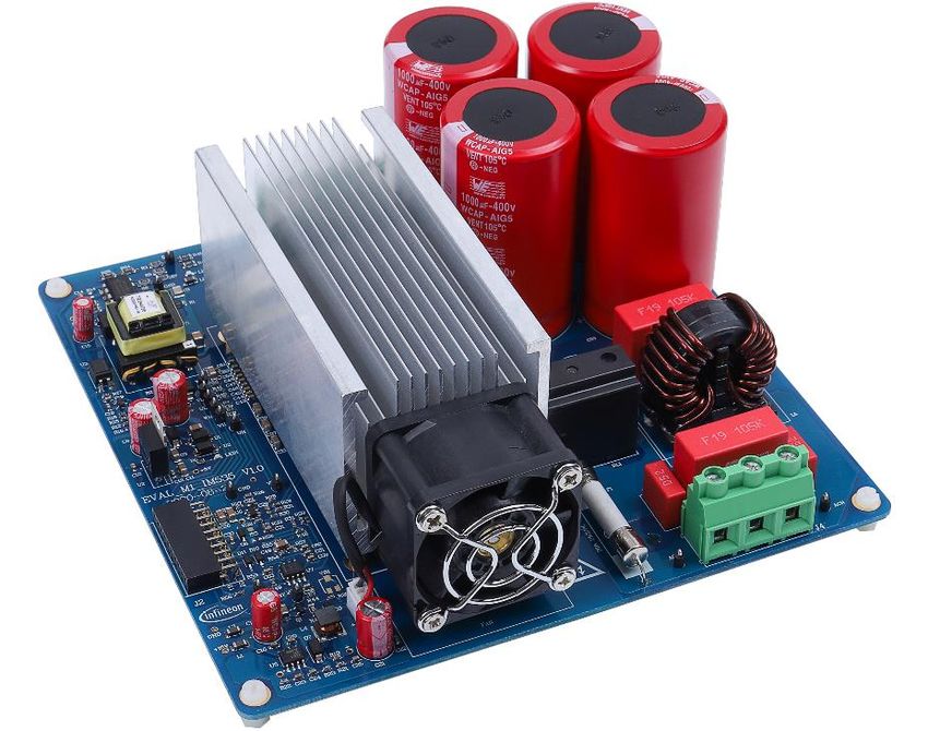
EVAL-M1-IM535 user guide
iMOTION™ modular application design kit
Table of contents

Table of contents
About this document ....................................................................................................................... 1
Important notice ............................................................................................................................ 2
Safety precautions.......................................................................................................................... 3
Table of contents ............................................................................................................................ 4
1 The board at a glance .............................................................................................................. 5
1.1 Delivery content ...................................................................................................................................... 5
1.2 Block diagram.......................................................................................................................................... 5
1.3 Main features ........................................................................................................................................... 7
1.4 Board parameters and technical data .................................................................................................... 7
2 System and functional description ........................................................................................... 9
2.1 Getting started with EVAL-M1-IN535 ...................................................................................................... 9
2.2 Description of the functional blocks..................................................................................................... 16
2.2.1 Overview of IM535-U6D .................................................................................................................... 16
2.2.2 Overview of ICE5AR4770BZS............................................................................................................ 17
2.2.3 Motor current sensing op-amp configuration and calculation ...................................................... 18
3 System design.......................................................................................................................20
3.1 Schematics ............................................................................................................................................ 20
3.2 Layout .................................................................................................................................................... 23
3.3 Bill of material ....................................................................................................................................... 25
3.4 Connector details .................................................................................................................................. 26
3.5 Test points ............................................................................................................................................. 27
4 System performance .............................................................................................................28
4.1 Heatsink thermal resistance test result................................................................................................ 28
4.2 Test results for output ability................................................................................................................ 29
4.3 Test results for PWM range.................................................................................................................... 31
4.4 Test results for overcurrent protection ................................................................................................ 32
4.5 Test results for over-temperature protection ...................................................................................... 34
4.6 Test result for DC bus voltage ripple..................................................................................................... 36
5 References and appendices ....................................................................................................37
5.1 Abbreviations and definitions ............................................................................................................... 37
5.2 References ............................................................................................................................................. 37
5.3 Ordering details and other information ............................................................................................... 37
Revision history.............................................................................................................................38

 4 of 39 V1.0
 2020-09-30
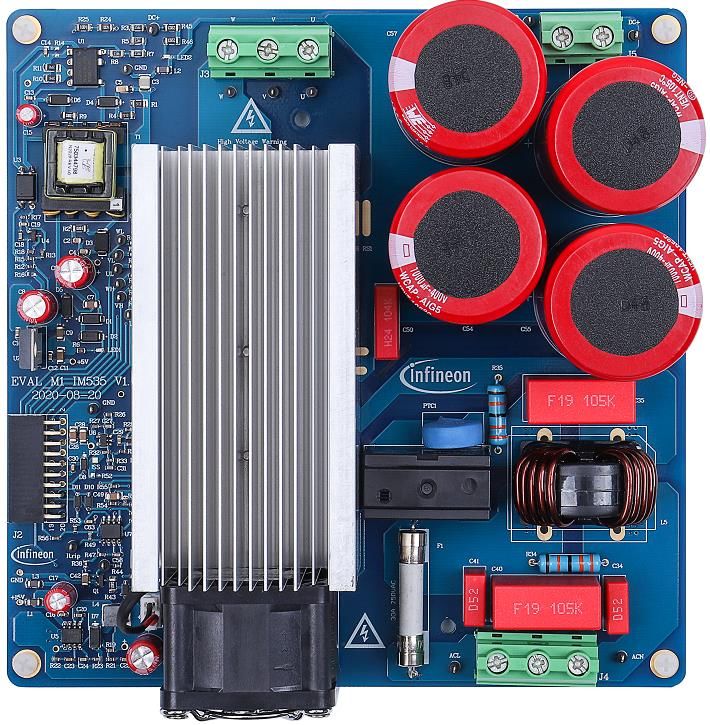
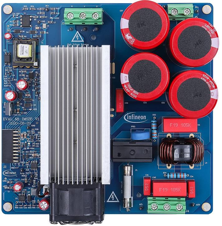
EVAL-M1-IM535 user guide
iMOTION™ modular application design kit
The board at a glance

 1 The board at a glance
The EVAL-M1-IM535 evaluation power board is a part of the iMOTION™ modular application design kit for motor
drives (iMOTION™ MADK). The MADK platform is intended for use with various power stages and different
control boards. The EVAL-M1-IM535 can easily be interfaced through the 20-pin iMOTION™ MADK M1 connector
such as EVAL-M1-101T, and is intended for single-motor control only.
The EVAL-M1-IM535 evaluation board is available through regular Infineon distribution partners as well as on
Infineon's website. The features of this board are described in the main features chapter of this document,
whereas the remaining paragraphs provide information to enable the customers to copy, modify and qualify
the design for production according to their own specific requirements.
Environmental conditions were considered in the design of the EVAL-M1-IM535, but the board is not qualified in
terms of safety requirements or manufacturing and operation over the entire operating temperature range or
lifetime. The boards provided by Infineon are subject to functional testing only.
The evaluation boards are not subject to the same procedures as regular products regarding returned material
analysis (RMA), process change notification (PCN) and product discontinuation (PD). Evaluation boards are
intended to be used under laboratory conditions by technical specialists only.

 1.1 Delivery content
The EVAL-M1-IM535 evaluation board is designed to provide an easy-to-use power stage based on the
Infineon's CIPOS™ Mini intelligent power module (IM535-U6D IPM).
The delivery includes the finished board as shown in Figure 1 and Figure 2. It provides a single-phase AC
connector, an EMI filter and soft power-up circuit, input rectifier, DC bus capacitors and 3-phase output for
connecting the motor.
It also contains CoolSETTM based auxiliary power supply to provide 15 V & 5 V, emitter shunts for current sensing
and overcurrent protection, and a voltage divider for DC-link voltage measurement. The board shown here can
be operated directly with the required power supply without the need for additional components.

 1.2 Block diagram
The block diagram of the EVAL-M1-IM535 is depicted in Figure 1.

 CIPOSTM IPM IM535-U6D

 Power 15V
 Line
 EMI Filter Supply
 & Soft PWM HVIC M
 Itrip
 Power Up
 Neutral
 15V & 5V

 Circuit
 PWM

 Overcurrent and
 DCBsense

 Overtemperature VFO
 protection
 VTH
 GK

 I_Shunt+
 20 pin iMOTIONTM
 MADK-M1 connector
 I_Shunt-

Figure 1 Block diagram of the EVAL-M1-IM535

 5 of 39 V1.0
 2020-09-30
EVAL-M1-IM535 user guide
iMOTION™ modular application design kit
The board at a glance

Figure 2 points out the functional groups on the top side of the EVAL-M1-IM535 design:

 5
 6
 7

 4

 9
 8 11
 3 2
 6

 10

 11
 12 1

 1. 220 VAC & PE input connector 8. iMOTIONTM MADK M1 connector (20-pin)
 2. EMI filter 9. Current sensing OPA (SGM721XN5)
 3. In-rush relay control 10. OCP & OCT comparator (LM393)
 4. DC bus capacitors 11. DCDC for cooling fan
 5. Connector for DC bus 12. BLDC cooling fan
 (For external PFC or DC source)
 13. Heat sink
 6. UVW motor phase connector
 7. Auxiliary power supply (IM535 + input rectifier + shunt resistor)

Figure 2 Functional groups of the EVAL-M1-IM535 reference design

 6 of 39 V1.0
 2020-09-30
EVAL-M1-IM535 user guide iMOTION™ modular application design kit The board at a glance 1.3 Main features The EVAL-M1-IM535 is an evaluation board for motor drive applications. Combined in a kit with one of the available MADK control board options, it demonstrates Infineon’s motion control IC and IPM technology for motor drives. The evaluation board characteristics include: • Input voltage 85~265 VAC • Maximum 20 A input and output current • Maximum 3000 W motor power output • On board EMI filter • Current sensing operational amplifier (OPA) with single shunt • Auxiliary power supply with 15 V, 5 V • Overcurrent hardware protection & over temperature protection • Sensing of DC-link voltage • Thermistor output • PCB is 166 mm × 166 mm, two layers with 2 oz. copper • RoHS compliant 1.4 Board parameters and technical data Table 2 depicts the important specifications of the evaluation board EVAL-M1-IM535. Table 2 EVAL-M1-IM535 board specifications Parameter Symbol Conditions / comments Value Unit Input voltage Vac Optimized design for 220 VAC application 85 ~ 265 Vrms Lower AC input, less motor power output Maximum input current Iac(max) Input 220 VAC, Ta=25C 20 Arms Maximum input power Pin(max) Input 220 VAC, fPWM = 6 kHz, Ta=25°C, Tcase= 105°C 3000 W Force cooling mode Maximum motor Imtr(max) Input 220 VAC, fPWM=5 kHz, Ta=25°C, Tcase= 105°C 20 Arms current Force cooling mode Maximum DC bus Vdc(max) DC bus capacitors are 400 V, 820µFX4 400 V voltage (or 1000µF X4) Minimum DC bus Vdc(min) Aux power supply brown-in voltage 80 V voltage Shunt Resistance Rsh Two 5 mΩ in parallel, with external OPA gain 10 2.5 mΩ Protections Motor current Itrip Wizard setup for OC trigger level, related to shunt 30 1 Apeak protection trigger level resistor RS1 & RS2 and current sensing bias 1 1 For iMOTION™ IC IMCxxx, there are three types of Gatekill input source options in MCEWizard setup: Gatekill-pin, Comparator and Both. If you select “comparator” mode, the external Gatekill signal will be not used, and the signal I_Shunt will be compared by the internal comparator with the “Device overcurrent trigger level setting” value set in MCEWizard. 7 of 39 V1.0 2020-09-30
EVAL-M1-IM535 user guide
iMOTION™ modular application design kit
The board at a glance

Parameter Symbol Conditions / comments Value Unit
Motor current Itrip Hardware comparator overcurrent protection, 36 Apeak
protection trigger level related to shunt resistor and LM393 setup
2
Thermal protection Tprotection Temperature gap between junction and NTC 105 °C
level (negative temperature coefficient) sensor needs
 to be considered; recommended is a setting of
 105°C or less

 Auxiliary power supply 1 – 15 V
Output voltage Vout1 Used for IPM and cooling fan 15 ± 5% V
Maximum output Iout1 450 mA
current

 Auxiliary power supply 2 – 5 V
Output voltage Vout2 Used for IMC controller and protection circuits 5 ± 1% V
Maximum output Iout2 150 mA
current

 PCB characteristics
Dimension Length × width × height 166×166×62 mm
Material FR4, 1.6 mm thickness, 2oz PCB

 System environment
Ambient temperature Ta Non-condensing, maximum RH of 95% 0 ~ 50 °C

 8 of 39 V1.0
 2020-09-30
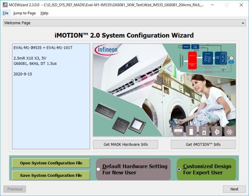
EVAL-M1-IM535 user guide iMOTION™ modular application design kit System and functional description 2 System and functional description 2.1 Getting started with EVAL-M1-IN535 In order to run the motor system, a combination of the iMOTION™ MADK power board (EVAL-M1-IM535) and the matching MADK control board (EVAL-M1-101T or other control board) are required. This chapter provides more details on setting up the system and getting started with the iMOTION™ MADK development platform. Note: If you are using an EVAL-M1-101T control board, please make the following changes to better match EVAL-M1-IM535 for op-amp current sensing, since EVAL-M1-101T’s default configuration is directly ADC sample. 1. Remove R6 of EVAL-M1-101T (Since EVAL-M1-IM535 uses external OPA circuit, it has its own bias) 2. Change R7 of EVAL-M1-101T from 2 kΩ change to 0 ohm (To reduce total R & C delay for current sensing path) The EVAL-M1-IM535 reference designs are tested with EVAL-M1-101T controller boards, which shipped with embedded firmware and default parameters. The following steps have to be performed in order to achieve a usable motor controller IC from a blank IMC101T: Programming of the motion control engine (MCE) Programming of parameter sets for system and motor Programming of customer scripts (optional) Programming of the combined file for an integrated system (optional) The iMOTION™ software tools, MCEDesigner and MCEWizard, are required to initially set up the system, as well as to control and fine-tune the system performance to match the user’s exact needs. These tools are available for download via the Infineon website (https://www.infineon.com/cms/en/product/power/motor-control- ics/digital-motor-controller-imotion/imc101t-t038/#!tools ). Please visit this page periodically to check for tool/software updates. iMOTION™ Link or on board USB-to-UART cable is needed to bridge the PC/debugger side and motor drive system (the target iMOTION™ device, hot side) with 1 kV DC galvanic isolation. This chapter provides more details on setting up the system and getting started with the iMOTION™ development platform. After downloading and installing the iMOTION™ PC tools, MCEWizard and MCEDesigner, the following steps need to be taken to run the motor. Refer to MCEWizard and MCEDesigner documentation for more information. Figure 3 shows the basic system connection using EVAL-M1-IM535 to run a 3KW GK6081-6AC31 motor with MCE Designer. 9 of 39 V1.0 2020-09-30
EVAL-M1-IM535 user guide
iMOTION™ modular application design kit
System and functional description

 Motor phase
 outputs

 To EVAL-M1-101T
 (controller board)

 AC
 Power
 Input

Figure 3 System connection example

Figure 4 MCEWizard welcome page

 10 of 39 V1.0
 2020-09-30
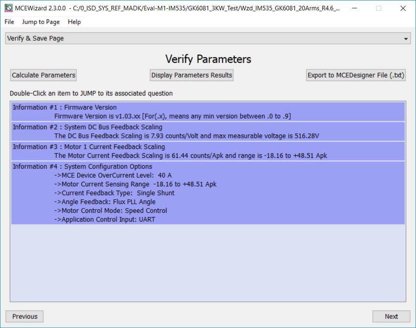
EVAL-M1-IM535 user guide
iMOTION™ modular application design kit
System and functional description

Figure 5 MCEDesigner user interface

Here are the steps needed to run the motor:
1. Connect EVAL-M1-101T control board to EVAL-M1-IM535, and connect PC-USB connector to EVAL-M1-101T.
2. Connect 220 V AC power supply and UVW outputs to the motor.
3. Use MCEWizard to enter the target motor’s system and operating parameters, as well as evaluation board’s
 hardware parameters, which will then be used to calculate the digital parameter set of the controller
 representing the complete motor drive system.
4. After system and operating parameters are set, go to the “Verify & Save Page” and click on “Calculate
 Parameters” button. If no errors are reported, then save the drive parameter set into your project directory
 by clicking “Export to MCEDesigner file (.txt)” (Figure 6); if an error is detected, double-click on the error
 message (highlighted in RED) and adjust the related parameter. The saved drive system parameter file will be
 later used by the MCEDesigner in step 9.
 (Please refer to MCEWizard_V2.3.0.0 User Guide.pdf for more details, which is in MCE Wizard’s install path)

 11 of 39 V1.0
 2020-09-30
EVAL-M1-IM535 user guide
iMOTION™ modular application design kit
System and functional description

Figure 6 MCEWizard Verify and Save page

5. Turn on 220 V AC power supply, red LED1 & LED2 ON.
6. Start MCEDesigner tool and open MCEDesigner default configuration file (.irc) for IMC101T device
 (IMC101T_Vxxx.irc) by clicking “File” > “Open”.
 (IMC101T_Vxxx.irc file is included in downloaded “IMC101T MCE Software Package”)
7. MCEDesigner should automatically connect to the EVAL-M1-101T board using default COM port (Indicated by
 green circle next to “COMx Up” status in the bottom frame of the MCEDesigner GUI). If it cannot establish the
 connection due to incorrect COM port, change COM port by doing the following steps: click on the “System
 Page” window and then click on “Preferences > Connection > Connect using”, and choose one of the other
 available COM ports from the drop-down list.

8. In case of blank IC: If the firmware has been erased from the IMC101T, a warning message will pop up saying
 “Target device firmware and parameters files are not programmed! (Figure 7) Please program firmware and
 parameters file.” See step 9 on how to obtain/program firmware and parameters.

Figure 7 MCEDesigner warning message

 12 of 39 V1.0
 2020-09-30
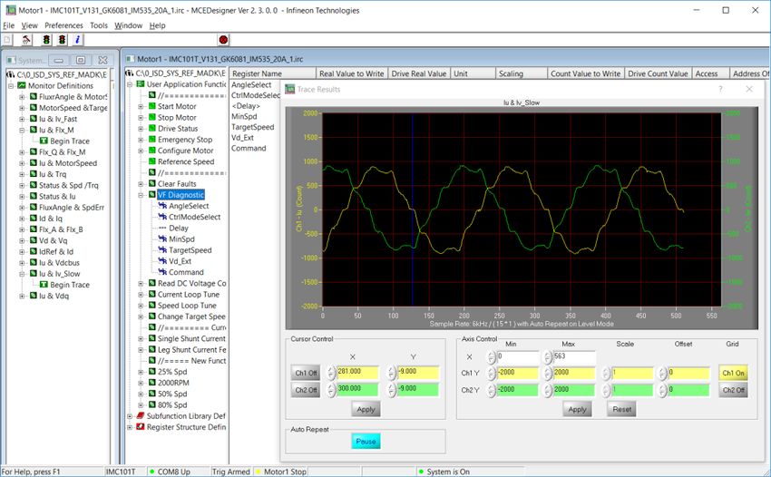
EVAL-M1-IM535 user guide
iMOTION™ modular application design kit
System and functional description

9. In case of blank IC: Take the following steps to program the firmware and the parameters file into the internal
 Flash memory of iMOTION™ Control IC: Click on system page, click “Tools” > “Programmer” and select
 “Program Firmware and Parameters,” shown as Figure 8 below. The encrypted firmware is available in
 “IMC101T MCE Software Package,” regarding the parameters file, browse and select the .txt file in step 3.

 (If blank IMC101T IC, MCE Designer will pop up information “Target device firmware and parameter files are not
 programmed!”) Program the MCE firmware and system parameters into the internal Flash memory of iMOTION™ IC by
 clicking “Tools > Programmer “in the pull-down menu, and then clicking on the “Program Firmware and Parameter”
 check box. Select right parameter file and firmware file. Finally click “Start” button to program firmware and parameter.
 Then click YES and then the OK button to update IRC file with parameter file; finally “Save As” the IRC file to your own file
 name that contains COM config, Parameters & firmware file path information.
 (Please refer to MCEDesigner User Guide.pdf and MCEDesigner_V2.3.0.0 Application Guide.pdf for more details, which
 is in MCE Designer’s install path)
 Red LED1 on EVAL-M1-101T will flash on after the program is done.

Figure 8 MCEDesigner program page

10. Double click “VF Diagnostic” function in motor1 page, monitor motor current with oscilloscope. If motor
 current is not sinusoidal, change target speed and Vd_Ext in VF Diagnostic sub-function, then double-click
 “VF Diagnostic” until oscilloscope shows a steady sinusoidal current, with amplitude of 30~50% motor rate
 current.
 Double-click “Iu & Iv_Slow” in System page > Monitor Definitions, the motor current feedback would be very
 clean and sinusoidal, as shown in Figure 9, otherwise please tune “Gating Propagation Delay & Phase Shift
 Window Size” in MCE Wizard. The sampled motor current noise amplitude should be less than 50 cts ~100
 cts (below 5% of motor current, or below 5% of max AD range 2048 cts); otherwise, motor current sample
 related hardware and setup need tuning.

 “VF Diagnostic” sub function can verify:
 • If motor is correctly connected
 • If IGBT / MOS & gate driver work as expected
 • If current sensing related parameters are correctly configured
 • If PCB layout and DC bus decouple have been done correctly
 After “VF Diagnostic” is done, click STOP button (the red traffic light button) to stop PWM.

 13 of 39 V1.0
 2020-09-30
EVAL-M1-IM535 user guide
iMOTION™ modular application design kit
System and functional description

Figure 9 Trace waveform for Iu & Iv open loop diagnostic

11. Start the motor by clicking the green traffic light button in the control bar (or double-click Start Motor sub
 function in Motor1 page, group of User Application Function Definitions); motor runs if above step goes well.
12. Check motor spin direction, adjust UVW connection order or set negative target speed in MCE Designer if
 direction is wrong.
13. Set target speed to about 50% of MAX speed, start “Iu & Flx_M” trace with “Auto Repeat On Level,” see
 Figure 10. Flx_M is better within the range of 2000~2500 (rated value is 2048), and MUST be steady and DC-
 like.

 Some key tips for better motor-performance tuning:
 • If Flx_M is not steady (swinging or oscillating), double-check motor parameters, speed loop PI gain, flux Estimator
 time constant and PLL PI bandwidth (parameters PLLKp & PLLKi) related setup.
 • If Flx_M is very noisy, double-check current feedback and Vdc-related hardware and parameters.
 • If Flx_M is far from 2048, “Motor Back EMF Constant (Ke)” needs to be adjusted in MCE Wizard.

 14 of 39 V1.0
 2020-09-30
EVAL-M1-IM535 user guide
iMOTION™ modular application design kit
System and functional description

Figure 10 Trace waveform for Iu & Flx-M at 50% speed

14. Once the firmware has been programmed, in case a new parameter file has to be programmed, follow the
 same instructions given in step 9. In this case, firmware programming is no longer needed and it is possible
 to select the first option “Program Parameters.”

Note: For detailed information on controller programming, refer to AN2018-33 iMOTION™ 2.0 Device Programming,
MCEDesigner documentation and MCEWizard documentation.

 15 of 39 V1.0
 2020-09-30
EVAL-M1-IM535 user guide
iMOTION™ modular application design kit
System and functional description

 2.2 Description of the functional blocks
The motor inverter of EVAL-M1-IM535 reference design is implemented by the IM535 module, and the auxiliary
power supply is based on fixed frequency CoolSETTM ICE5AR4770BZS.
Motor current sensing is single shunt mode, with an external OPA SGM721XN5 for 10 X gain.

 2.2.1 Overview of IM535-U6D
Figure 11 illustrates the internal block diagram of the CIPOS™ Mini IPM IM535-U6D.
Main features include:
• 3 half bridges with TRENCHSTOP™ 30 A / 600 V and antiparallel diodes for inverter section
• Very low thermal resistance due to DCB
• Rugged SOI gate driver technology with stability against transient and negative voltage
• Negative potential allowed up to VS = -11 V for single transmission at VBS = 15 V
• Integrated bootstrap functionality
• Overcurrent shutdown, and build-in temperature monitor
• Undervoltage lockout and all six switches turn off during protection
• Low-side emitter pins accessible for phase current monitoring (open emitter)
• Cross conduction prevention and sleep function

Figure 11 IM535 internal block

 16 of 39 V1.0
 2020-09-30
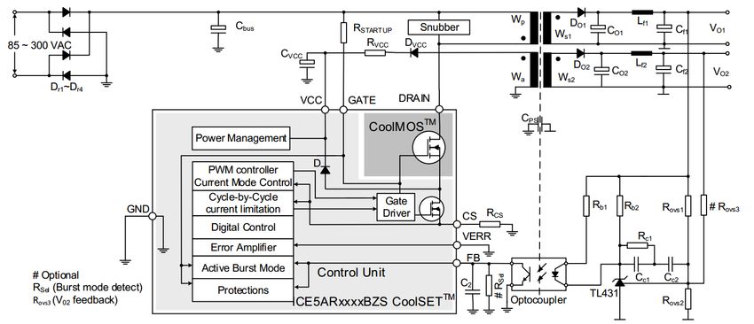
EVAL-M1-IM535 user guide
iMOTION™ modular application design kit
System and functional description

 2.2.2 Overview of ICE5AR4770BZS
The ICE5AR4770BZS is Infineon’s latest 5th generation fixed frequency CoolSETTM, offers high performance and
integration of latest generation of 700 V CoolMOSTM superjunction MOSFETs in DIP-7 package.
Figure 12 illustrates the internal block diagram and typical isolated flyback application.

Figure 12 ICE5AR4770BZS internal block and typical application in isolated flyback mode

Main features of ICE5AR4770BZS include:

• 100 kHz maximum switching frequency with 700 V integrated MOSFET
• Power delivery of up to 15 W with universal wide input range (85~300 VAC) DCM design
• Brown-in protection, fast and robust start-up operation with cascode configuration
• 3-level selectable entry/exit active-burst mode profile (optional)
• Built-in digital soft-start
• Cycle by cycle peak current limitation
• Support both DCM and CCM operation with slope compensation
• Integrated error amplifier to support direct feedback typical with non-isolated flyback topology
• Digital frequency reduction with decreasing load for higher efficiency
• Frequency jitter and soft gate driving for low EMI
• Limited charging current for VCC pin short to ground
• Comprehensive protection with VCC over voltage, VCC undervoltage, overload/open loop, over-temperature
 protection
• Auto-restart for all protection features

 17 of 39 V1.0
 2020-09-30
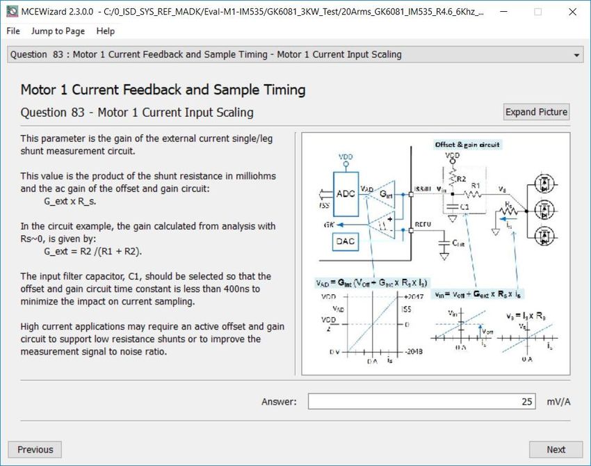
EVAL-M1-IM535 user guide
iMOTION™ modular application design kit
System and functional description

 2.2.3 Motor current sensing op-amp configuration and calculation
In order to suppress common mode noise between this power board and the MADK control board, an 11 MHz
rail-to rail I/O CMOS OPA SGM721XN5 is used for motor current sensing.
Two 5 mΩ 2.5 W (2512 package) shunt resistor and 10X external-gain OPA is the default configuration for the
EVAL-M1-IM535 evaluation design, which means 1 A motor current produces 25 mV voltage to ADC input,
MCEWizard’ s “Motor1 Current Input Scaling” needs input of 25 mV/A.

Figure 13 Current feedback configuration in MCEWizard for EVAL-M1-IM535

Figure 14 Current feedback with external 10X op-amp

Figure 14 shows the external amplifier gain circuit in EVAL-M1-IM535 evaluation design, which is a typical
differential amplifier based on SGM721XN5, with input low-pass filter (LPF) and operational bias. C29, R28, R29,

 18 of 39 V1.0
 2020-09-30
EVAL-M1-IM535 user guide
iMOTION™ modular application design kit
System and functional description

R30 and R31 build the input differential mode LPF, which can damp parts of PWM switching noise. The default
LPF time constants is 2*RC = 2*(R28//R29)*C29 = 470 ns. The typical setup time is 0.1~0.5 µs, which depends on
PCB layout, DC bus decouple capacitor and IGBT / MOS gate driver configuration.
For better common-mode noise-rejection ability, a balanced differential amplifier is highly recommended,
which means R33 is equal to the value of R26 & R27 in parallel.
The divider of R26 & R27 provide operational bias for the amplifier, which affects the maximum motoring
current and regeneration current range. With the default configuration of EVAL-M1-IM535, R26=22 k & R27=220
k, the op-amp operational bias is 5000 mV * 22 / (22+220) = 454 mV, which means:
- Op-amp outputs 454 mV at zero motor current (motor stopped), 454 mV/op-amp gain/RS1 is the maximum
 allowable regeneration current.
- If 1X ADC internal gain is selected, 4546 mV range for motor current sensing (5000 mV – 454 mV = 4546 mV).
 And 4546 mV/op-amp gain/RS1 is the maximum allowable motor current. “Motor Rated Amps * Motoring
 Current Limit” should be below this maximum allowable range.
- If 3X ADC internal gain is selected, 1212 mV range for motor current sensing (5000/3 – 454 mV = 1666 - 454
 mV = 1212 mV). And “1212 mV/op-amp gain/RS1” is the maximum allowable motor current. “Motor Rated
 Amps * Motoring Current Limit” should be below this maximum allowable range.
- For applications that never work at regeneration mode (e.g. air conditioner), the OPA output bias wastes
 the available range of ADC, and reduces the available ADC range.
- For applications that need more current range for regeneration (e.g. fan application), the amplifier bias
 needs an increase based on the regeneration requirement. For example, R26 = R27 = 2 * R33 for a bias of
 2.5 V (50% of AD range) so that they have the same range for motoring current and regeneration current.

Please note that EVAL-M1-101T default configuration is in direct current sensing mode, R6 & R7 on EVAL-M1-
101T are not needed for EVAL-M1-IM535’s motor current sensing. We need to remove R6, and short R7 on
EVAL-M1-101T control board, as shown in Figure 15.

Figure 15 Modification on EVAL-M1-101T (remove R6 and short R7)

 19 of 39 V1.0
 2020-09-30
EVAL-M1-IM535 user guide
iMOTION™ modular application design kit
System design

 3 System design
The EVAL-M1-IM535 board is an optimized design for 220 V major home appliances like air conditioners
applications. To meet individual customer requirements and to make the EVAL-M1-IM535 reference design a
basis for development or modification, all board design data such as schematics, Gerber and Altium design
data can be found on the Infineon homepage.

 3.1 Schematics
The overall schematic diagram for EVAL-M1-IM535 are provided in Figure 16 and Figure 17.

Figure 16 Aux power supply for EVAL-M1-IM535

Figure 16 shows the 8 W isolated flyback power supply based on ICE5AR4770BZS, +15 V and +5 V output for IPM
and controller board, the major function information are listed as below:
- Transformer T1 is based on EE16 core, and the rated power is 8 W, which is suitable for most air
 conditioner applications
- R3, R5, R7 and R8 decide the brown-in and brown-out voltage for power-on and power-off, which means
 ICE5AR4770BZS start work when DC bus voltage is over 82 V and stop work when DC bus below 40 V.
- R10 and R11 sensing the maximal peak current, related to cycle-by cycle current limitation.
- R15, R16 and R18 decide the output voltage for +15 V and +7 V.
- U5 is the DC-DC controller for cooling fan speed, R19, R23 and R21 can be adjusted to tune initial fan speed
 and adjustment based on IPM temperature. VR1 is reserved for manual fan speed adjustment (by
 removing R20).
- 12 V power supply for relay control is from +15 V via D1 and D2, which is not very accurate

 20 of 39 V1.0
 2020-09-30
EVAL-M1-IM535 user guide
iMOTION™ modular application design kit
System design

- PC817 used for primary isolation of flyback power supply, is not for real isolation, but for easier PCB layout
 for signal ground and power ground connections. This can reduce common-mode noise for controller
 board, and achieve higher SNR for motor current sensing.
Figure 17 shows the invertor section of EVAL-M1-IM535, which contains IM535-U6D and its peripheral circuits,
the major function information is listed below:
- U6 (SGM721) is a typical balanced difference amplifier for 10 X gain, the OPA bias decided by divider of R26
 & R27; C29, C27 and C31 effect the total LPF bandwidth.
- U7A (LM393) for overcurrent protection; R50 is the major resistor for overcurrent threshold adjustment.
- U7B (LM393) for over-temperature protection; the pull-up resistor for IPM internal NTC is not a unique
 device, which is a combination of R55, R56, D10 and circuit in “Gatekill” and “IPM_TEMP” networks on
 control board, it is not recommended to change the hardware setup of U7B. Please adjust MCEWizard
 setup for over-temperature protection as shown in Figure 17, which is easier and safer.
- J5 is reserved for Vdc bus voltage test or applications that use external DC source or PFC circuits.
- C54 ~ C57 are DC bus capacitors; default value is 400 V, 820 µF or 1000 µF. Please replace them by 450 V
 capacitors if there are external 380 V PFC or over 265 VAC inputs.
- L5 is common-mode choker, which is the key component for EMI performance. Two packages placed on
 the PCB for convenient EMI performance testing and evaluation, suitable for 3 ~ 9 mH and 18~23 A
 common mode inductor.
- J2 is 20-pin interface for MADK control boards; only pin 10 & pin 12 (IU+ & IU-) are used for single-shunt
 current sensing (ISS from OPA output).

 21 of 39 V1.0
 2020-09-30
EVAL-M1-IM535 user guide
iMOTION™ modular application design kit
System design

Figure 17 Schematics for IM535 IPM and peripheral circuit

 22 of 39 V1.0
 2020-09-30
EVAL-M1-IM535 user guide
iMOTION™ modular application design kit
System design

 3.2 Layout
This board has two electrical layers with 70 µm copper (2 oz. copper) and dimensions of 166 mm × 166 mm.
The thickness of the PCB board is 1.6 mm. Figure 18 illustrates the top assembly print of the reference design.

Figure 18 Top assembly print of the EVAL-M1-IM535 reference design

 23 of 39 V1.0
 2020-09-30
EVAL-M1-IM535 user guide
iMOTION™ modular application design kit
System design

The top layer and bottom layer routing of the PCB are provided in Figure 19 and Figure 20.

Figure 19 Top layer routing of the EVAL-M1-IM535

Figure 20 Bottom layer routing of the EVAL-M1-IM535

 24 of 39 V1.0
 2020-09-30
EVAL-M1-IM535 user guide
iMOTION™ modular application design kit
System design

 3.3 Bill of material
Table 3 shows the major parts of EVAL-M1-IM535 design.
The complete bill of material is available on the download section of the Infineon homepage. A log-in is
required to download this material.

Table 3 BOM of the most important/critical parts of the evaluation or reference board
 Ref
 S. No. Description Manufacturer Manufacturer P/N
 Designator
 U6 SGM721XN5 11MHz, 8.5V/µS, Rail-to-Rail OPA SG Micro SGM721XN5/TR
 U7 LM393 Dual comparator
 Infineon
 Q1 IRLML2030 30V 154mOhm@4.5V MOSFET Technologies IRLML2030
 Infineon
 U8 IM535-U6D CIPOS MINI
 TM
 Technologies IM535-U6D
 1.8A DC/DC Step-Down Voltage Infineon
 U5 IFX91041EJV Regulator, Adjustable Technologies IFX91041EJV
 Infineon
 U1 ICE5AR4770 Fixed Frequency 700 V CoolSETTM Technologies ICE5AR4770BZS DIP-7
 RL1 G4A-1A-PE 20A Relay
 FAN4028 12V 3.36W, 14500rpm,
 FAN FAN4028 19.1CFM; SANYO 9GA0412P3H01
 BR1 D25XB60 25A 600V Diode Bridge
 Diameter 35mm,
 Height 45mm~60mm, Wurth
 C54~C57 820uF, 400V 820uF~1000uF, 400V Elektronik 861021386035
 Wurth Electronics Midcom
 (750343739), Core: 150-2182
 (EE16/8/5), bobbin: 070-5280 (9-pin Wurth
 T1 710uH/EE16 EXT, THT, horizontal version) Electronics 750343739
 R24, R25 680k 1206 Thick Film Chip Resistor
 WE-CBF SMD EMI Suppression Wurth
 L1, L2, L3 650R Ferrite Bead Elektronik INDC3216X130N
 C50 470nF / 630V CBB22 Film Capacitors
 F1 30A 250VAC 30A 250VAC fuse
 Film Capacitor, THT, L13W5H10, Wurth
 C34, C41 5.6nF, 275V 5.6nF, 275V Elektronik 890324023002CS
 RS1, RS2 5mR Current Sense Precision Resistor Isabellenhuette BVT-I-R005
 WE-CMBNC Common Mode Power Wurth
 L5 3mH Line Choke, Type XL, 3mH, 23A, 250V Elektronik 7448052303
 WCAP-FTX2 Film Capacitor, THT, Wurth
 C35, C40 1uF, 275V L26W11H20, 1uF, 275V Elektronik 890324026027CS

 25 of 39 V1.0
 2020-09-30
EVAL-M1-IM535 user guide
iMOTION™ modular application design kit
System design

 3.4 Connector details
General information about the connectors of the EVAL-M1-IM535 reference design is provided in this section.
Table 4 includes the details of the AC input connector.

Table 4 AC input connector (J4)
PIN Label Function
1 L AC line
2 N AC neutral
3 PE Protection earth

Table 5 provides the details of the motor UVW output connector J3.

Table 5 Motor side connector (J3)
PIN Label Function
1 U Connected to motor phase U
2 V Connected to motor phase V
3 W Connected to motor phase W

Table 6 provides the details of the DC bus output connector J5, for external PFC or DC source connection.

Table 6 DC bus connector (J5)
PIN Label Function
1 DCP Connected to DC+
2 GND Connected to DC-

Table 7 provides the pin assignments of the 20-pin iMOTION™ MADK-M1 interface connector J2. This connector
is the interface to the controller board.

Table 7 J2 - iMOTION™ MADK-M1 20-pin interface connector for controller board
Pin Name Pin name connectors
1 PWMUH 5 V compatible logic input for high side gate driver-Phase U
2 GND Ground
3 PWMUL 5 V compatible logic input for low side gate driver-Phase U
4 GND 4 GND ground
5 PWMVH 5 V compatible logic input for high side gate driver-Phase V
6 +5 V On board 5 V supply
7 PWMVL 5 V compatible logic input for low side gate driver-Phase V
8 +5 V On board 5 V supply
9 PWMWH 5 V compatible logic input for high side gate driver-Phase W

 26 of 39 V1.0
 2020-09-30
EVAL-M1-IM535 user guide
iMOTION™ modular application design kit
System design

Pin Name Pin name connectors
10 I_U Positive current sense output
11 PWMWL 5 V compatible logic input for low side gate driver-Phase W
12 I_U- Negative current sense output or ground
13 GK Gatekill signal – active low when overcurrent is detected
14 DCBSense DC bus positive voltage, scaled in 0-5 V range by a voltage divider
15 VTH Thermistor output
16 I_V Not used
17 I_V- Not used
18 I_W Not used
19 I_W- Not used
20 VCC 15 V power supply

 3.5 Test points
Table 8 provides the assignments of the on-board test points.

Table 8
Pin Name Functions & net label describe
X1 UH High side gate driver PWM-Phase U
X2 U Invertor output, motor phase U
X3 UL Low side gate driver PWM-Phase U
X4 V Invertor output, motor phase V
X5 VH High side gate driver PWM-Phase V
X6 VL Low side gate driver PWM-Phase V
X7 W Inverter output, motor phase W
X8 WH High side gate driver PWM-Phase W
X9 WL Low side gate driver PWM-Phase W
X10 GND Ground test point for controller board (signals ground )
X11 ACL AC voltage measure point (L)
X12 ACN AC voltage measure point (N)
X13 DNI
X14 Itrip Output of over current protection circuit (Pin 1 for LM393)
X15 GND Power GND test point (DC-)
X16 VTH Test point for temperature sensing (Pin 15 of IM535)
X17, X18 DC+ DC+ test point
X19 GND Ground test point for primary side of fly-back power supply

 27 of 39 V1.0
 2020-09-30
EVAL-M1-IM535 user guide
iMOTION™ modular application design kit
System performance

 4 System performance
 4.1 Heatsink thermal resistance test result
In order to test the thermal impedance of heatsink to ambient RthCA, the DC source is used to conduct the IPM
internal diodes, as shown in Figure 21. With the DC source voltage increasing, current through IPM IIPM and
voltage on IPM VIPM are monitored by current and voltage meter, the IPM case-temperature test point is
between IPM and heatsink, the same as Tc point of inverter IGBT of the IPM datasheet.

 CIPOSTM IPM IM535-U6D

 -
 PCB
 V +
 VIPM
 Case temperature (Tc) test point
 `

 IIPM
 A Heatsink
Figure 21 Heatsink thermal testing set-up

Thermal resistance between junction to ambient RthJA is divided into 2 parts as in the following formula: thermal
resistance between junction to case RthJC and thermal resistance between case to ambient RthCA.
 ℎ = ℎ + ℎ

Thus, we get the following formula:
 ∆ −
 ℎ = =
 . ×
According to the test set-up, the test results are shown in Figure 22 below. The IPM case temperature is
detected for about one hour until the temperature is stable.

Figure 22 Heatsink thermal testing result

 28 of 39 V1.0
 2020-09-30
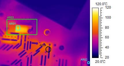
EVAL-M1-IM535 user guide iMOTION™ modular application design kit System performance Therefore, the final case-to-ambient resistance value is roughly: ℎ = 2.4 ℃/ Please note that: • 2.4 ℃/ thermal resistance is calculated with a fan voltage of 10 V. • DC-DC output voltage for EVAL-M1-IM535’s cooling fan is 7~14.3 V in default hardware configuration, which is adjusted by IPM temperature from 25 ~ 125℃ • Cooling fan’s rate voltage is 12 V corresponding to 110℃ IPM surface temperature. • Tuning R19, R23 and R21 can change the relationship between fan speed (voltage) and IPM temperature 4.2 Test results for output ability In order to test the total output power capability of EVAL-M1-IM535 design, the IPM case temperature is tested with different MADK input power and motor output current. The test conditions are: Ambient temperature Ta=25℃ Cooling fan voltage is 14.3 V , 8m/s air flow after heatsink (5 mm distance center of heatsink fins) AC input is VAC=220 V/50 Hz (VDC bus is 290 V~310 V) PWM frequency 6 kHz, three-phase modulation, about 40% VDQ modulation (1000 RPM) Figure 23 shows how to monitor IPM case temperature by infrared camera from the window on PCB bottom. Run motor at 1000 RPM and adjust motor load until the hottest point in the center of IM535-U6D reaches 105℃ (temperature rise reaches 80℃ ), get the curve for temperature rise and input power as shown in Figure 24. Figure 23 Infrared camera image for IPM temperature test 29 of 39 V1.0 2020-09-30
EVAL-M1-IM535 user guide
iMOTION™ modular application design kit
System performance

 Input Power Vs Delta T
 90

 80
 Delta T (℃)

 70

 60

 50

 40

 30

 20

 10
 Input Power (W)
 0
 0 500 1000 1500 2000 2500 3000 3500

 Output current Vs Delta T

 90

 80
 Delta T (℃)

 70

 60

 50

 40

 30

 20

 10
 Motor current (A)
 0
 0 5 10 15 20 25

Figure 24 EVAL-M1-IM535 output power capability test result

 30 of 39 V1.0
 2020-09-30
EVAL-M1-IM535 user guide iMOTION™ modular application design kit System performance 4.3 Test results for PWM range Figure 25 shows the output ability at different PWM frequencies, which are performed under the following conditions: 4~20 kHz PWM, three-phase modulation Run GK6081 motor at 1000RPM (about 40% VDQ modulation) and increase motor load at given PWM frequency, till the hottest case temperature of IM535-U6D reaches 105℃ Ambient temperature Ta=25℃ Cooling fan voltage is 14.3 V , 8m/s air flow after heatsink (5 mm distance, center of heatsink fins) AC input is VAC=220 V/50 Hz (VDC bus is 290 V~310 V) 23 Output current Vs PWM frequency 22 Output Current (A) 21 20 19 18 17 16 15 PWM frequency (kHz) 14 2 4 6 8 10 12 14 16 18 20 22 Figure 25 Output ability at different PWM frequency 31 of 39 V1.0 2020-09-30
EVAL-M1-IM535 user guide iMOTION™ modular application design kit System performance 4.4 Test results for overcurrent protection The IM535 product family provides an overcurrent detection function by connecting the ITRIP input with the IGBT current feedback, and IGBT short-circuit withstand time is 5 µs. Overcurrent detection generates a shutdown of outputs of the gate driver if ITRIP pin input is over 525 mV and lasts longer than 300ns. An external LM393 comparator is used for overcurrent protection in EVAL-M1-IM535 design to lower the request of shunt resisters voltage to 90 mV, since 525 mV means too much current for 2.5 mOhm shunt resisters. Figure 26 IPM overcurrent protection and over-temperature protection circuit The small signal and big signal response of this overcurrent protection circuit is shown in Figure 27: 2.3 µs for 300 ~ 400 mV shunt resistor voltage, which means 120 ~ 160 A short-circuit condition 5.9 µs for 100~150 mV shunt resistor voltage, which means 40 ~ 60 A overcurrent circuit condition 32 of 39 V1.0 2020-09-30
EVAL-M1-IM535 user guide
iMOTION™ modular application design kit
System performance

Figure 27 Overcurrent protection response waveform (CH1: IFB+, CH2: VFO, CH3: Itrip)

 33 of 39 V1.0
 2020-09-30
EVAL-M1-IM535 user guide
iMOTION™ modular application design kit
System performance

 4.5 Test results for over-temperature protection
The IM535 IPM has an internal NTC resistor, which connects to VFO multifunction pin, as shown in Figure 28:

Figure 28 Temperature sensing for IM535-U6D

The IM535-U6D IPM built-in NTC thermistor is 85 kOhm at 25℃ and its B-constant is 4092, typical resistance and
output of temperature-sensing voltage are listed in Table 9.

Table 9 NTC – Thermistor Characteristics
Temperature Resistance
 Vout (mV)
(℃) (kOhm)
50 29.972 4220
60 20.515 4160
70 14.315 4080
80 10.169 4000
90 7.345 3920
100 5.388 3830
110 4.009 3720
120 3.024 3600
125 2.639 3520

Given that the VFO pin is fault-output compatible pin (LOW true at IPM fault status), the temperature sensing
pull-up resistor needs to keep the temperature detection output as far away from the digital IO’s low level
threshold as possible, which means the available range should be beyond 3.5 V (0.7 x VDD) to make sure IMC101T
in EVAL-M1-101T considers this input as HIGH.
The pull-up resistor NTC is a complex network (R55, R56, D10 and circuit in EVAL-M1-101T), the final
temperature protection (OTP) circuit output voltage to IMC101T’s temperature-related AD input is shown in
Figure 29.

 34 of 39 V1.0
 2020-09-30
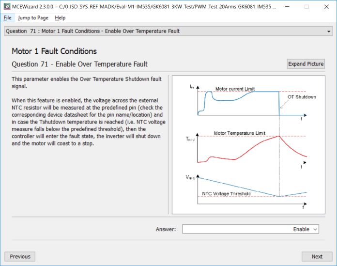
EVAL-M1-IM535 user guide
iMOTION™ modular application design kit
System performance

 VFO Output

 4400

 4200

 4000
 Output (mV)

 3800

 3600

 3400

 3200
 IPM Case Temperature (℃)
 3000
 25 35 45 55 65 75 85 95 105 115 125

Figure 29 OTP (NTC circuit) and output voltage curve

Please note that output of VFO pin is very noisy; EVAL-M1-101T’s OTP function might be triggered by noise.
Normally the MCEWizard setup needs to consider a margin for the input noise, for example, setup 3.3 ~ 3.4 V in
MCEWizard corresponding to the real shutdown temperature of 110 ~ 120°C.

To activate over-temperature protection, 2 setups in MCEWizard are needed, as shown in Figure 30 :
- Enable over-temperature shutdown function
- Set voltage for shutdown

Figure 30 Over-temperature protection setup in MCEWizard

 35 of 39 V1.0
 2020-09-30
EVAL-M1-IM535 user guide
iMOTION™ modular application design kit
System performance

 4.6 Test result for DC bus voltage ripple
The EVAL-M1-IM535 design does not equip PFC function, which means the DC bus voltage is determined by the
AC input voltage and the load of motor; the DC bus voltage ripple is the function of IPM inverter load and grid
input.
Figure 31 shows the DC bus ripple waveform with 4 x 1000µF capacitors, 220 VAC, 3000 W input power, which is
7.5% (23.6 V / 311 V = 7.5%).

Figure 31 Vdc ripple test at 3 kW input power

 36 of 39 V1.0
 2020-09-30
EVAL-M1-IM535 user guide
iMOTION™ modular application design kit
References and appendices

 5 References and appendices
 5.1 Abbreviations and definitions
Table 10 Abbreviations
 Abbreviation Meaning
 CE Conformité Européenne
 EMI Electromagnetic interference
 UL Underwriters Laboratories
 OPA Operational amplifier
 LPF Low-pass filter

 5.2 References
[1] Datasheet of Infineon IM535-U6D
[2] Datasheet of Infineon IMC101T
[3] MCEWizard User Guide
[4] MCEDesigner User Guide
[5] Infineon-MCESW-RM-User Manual

 5.3 Ordering details and other information
The power board is now available for customers in small order quantities. In order to initiate the testing,
customers are advised to order the following items:

 Base Part Number Package Standard Pack Orderable Part Number
 Form Quantity
EVAL-M1-IM535 EVAL Boxed 1 EVALM1IM535TOBO1
ICE5AR4770BZS DIP-7 PG-DIP-7 TUBE 2000 ICE5AR4770BZSXKLA1
IM535-U6D DIP 36x21D TUBE 280 IM535U6DXKMA1

 37 of 39 V1.0
 2020-09-30
EVAL-M1-IM535 user guide
iMOTION™ modular application design kit
Revision history

Revision history

Document Date of release Description of changes
version
V1.0 2020-9-30 First release

 38 of 39 V1.0
 2020-09-30
Trademarks
All referenced product or service names and trademarks are the property of their respective owners.

 For further information on the product, technology,
Edition 2020-09-30 delivery terms and conditions and prices please
 Published by contact your nearest Infineon Technologies office
 (www.infineon.com).
 Infineon Technologies AG
 81726 Munich, Germany WARNINGS
 Due to technical requirements products may contain
 dangerous substances. For information on the types
 in question please contact your nearest Infineon
 © 2020 Infineon Technologies AG. Technologies office.
 All Rights Reserved.
 Except as otherwise explicitly approved by Infineon
 Do you have a question about this Technologies in a written document signed by
 authorized representatives of Infineon
 document? Technologies, Infineon Technologies’ products may
 Email: erratum@infineon.com not be used in any applications where a failure of the
 product or any consequences of the use thereof can
 reasonably be expected to result in personal injury.
 Document reference
 UG2020-29
You can also read