SX2 Technical User Guide - Control Devices Group
←
→
Page content transcription
If your browser does not render page correctly, please read the page content below
SX2 Technical User Guide

 LMRK005IMU-###-##-300/400
 LMRK007IMU-####-##-330
 LMRK007XIMU-####-##-330
 G300D-###-300/400

Gladiator Technologies
ATTN: Technical Support
8022 Bracken Place SE
Snoqualmie, WA 98065 USA
Telephone 425.363.4180
Email: support@gladiatortechnologies.com
Web: www.gladiatortechnologies.com

 958-00006-001 Copyright © 2021 Gladiator Technologies – Proprietary
1 TABLE OF CONTENTS
1 TABLE OF CONTENTS.............................................................................................................................................................................................................2
2 TABLE OF FIGURES ................................................................................................................................................................................................................4
3 SAFETY AND HANDLING INFORMATION ..........................................................................................................................................................................5
4 GETTING STARTED .................................................................................................................................................................................................................6
 PRODUCT DEFINITIONS ...................................................................................................................................................................................................6
 4.1.1 VELOX® & VELOX® Plus ................................................................................................................................................................................6
 GLAMR ............................................................................................................................................................................................................................7
 4.2.1 Installation .............................................................................................................................................................................................................7
 4.2.2 USB Converter Box and Accessories ..............................................................................................................................................................9
 4.2.3 Connecting to Glamr ...........................................................................................................................................................................................9
 4.2.4 Running Glamr ....................................................................................................................................................................................................11
 4.2.5 Special Device Driver Settings ...................................................................................................................................................................... 13
 4.2.6 Select Applicable Baud Rate .......................................................................................................................................................................... 15
 4.2.7 Self-Test in Glamr ............................................................................................................................................................................................. 16
 4.2.8 Setting Output Configuration Options ......................................................................................................................................................... 17
 Set Message Rate ....................................................................................................................................................................................... 18
 Set Bandwidth ............................................................................................................................................................................................. 19
 Set Output Resolution................................................................................................................................................................................20
 Data Recording Feature ............................................................................................................................................................................ 21
 4.2.9 Troubleshooting with Messages ....................................................................................................................................................................23
5 PATENT AND TRADEMARK INFORMATION ...................................................................................................................................................................24
6 APPLICABLE EXPORT CONTROLS...................................................................................................................................................................................24
7 USER LICENSE......................................................................................................................................................................................................................24
8 STANDARD LIMITED WARRANTY ...................................................................................................................................................................................24
9 QUALITY MANAGEMENT SYSTEM ...................................................................................................................................................................................24
10 THEORY OF OPERATION ....................................................................................................................................................................................................25
 OUTLINE AND 3D SOLID MODELS................................................................................................................................................................................26
 CENTER OF GRAVITY ....................................................................................................................................................................................................26
 SYSTEM BLOCK DIAGRAM............................................................................................................................................................................................ 27
11 MESSAGE PROTOCOL ........................................................................................................................................................................................................28
 SERIAL COMMUNICATION SETTINGS ............................................................................................................................................................................28
 MESSAGE PACKET FORMAT..........................................................................................................................................................................................28
 SAMPLE DATA FORMAT ................................................................................................................................................................................................28
 11.3.1 Interfacing without Glamr ........................................................................................................................................................................29
 EXTERNAL SYNC INPUT ................................................................................................................................................................................................30
 11.4.1 Specifications ..............................................................................................................................................................................................30
 11.4.2 Timing Diagrams .........................................................................................................................................................................................30
12 SUMMARY OF TEST METHODS ........................................................................................................................................................................................ 31
958-00006-001 Technical User Guide

 CALIBRATION................................................................................................................................................................................................................ 31
 ENVIRONMENTAL .......................................................................................................................................................................................................... 31
 12.2.1 Sensor Validation ........................................................................................................................................................................................ 31
 12.2.2 Shock ............................................................................................................................................................................................................. 31
 12.2.3 Temperature Cycle ..................................................................................................................................................................................... 31
 12.2.4 Burn-In ........................................................................................................................................................................................................... 31
 12.2.5 Trend .............................................................................................................................................................................................................. 31
 12.2.6 Sensor Saturation ....................................................................................................................................................................................... 31
 RANDOM AND SINE VIBRATION....................................................................................................................................................................................32
 12.3.1 Random Vibration .......................................................................................................................................................................................32
 12.3.2 Sine Vibration Test .....................................................................................................................................................................................32
 RATE LINEARITY ...........................................................................................................................................................................................................32
 THERMAL......................................................................................................................................................................................................................32
 BIAS AND SCALE FACTOR OVER TEMPERATURE (VERIFY) ........................................................................................................................................... 32
 ATP (ACCEPTANCE TEST PROCEDURE) .......................................................................................................................................................................33
 12.7.1 Rate Spin.......................................................................................................................................................................................................33
 12.7.2 IMU Tumble ..................................................................................................................................................................................................33
 FAST-TOT ...................................................................................................................................................................................................................33
 TURN-ON TO TURN-ON OVER TEMPERATURE (TOT) .................................................................................................................................................. 33
 BIAS TURN-ON FROM A COLD START (LONG RUN) .............................................................................................................................................. 33
 BIAS IN-RUN .........................................................................................................................................................................................................33
 ANGLE RANDOM WALK AND ALLAN DEVIATION.....................................................................................................................................................34
 VELOCITY RANDOM WALK AND ALLAN DEVIATION................................................................................................................................................34
 AMBIENT POWER SWITCHING TOT (APSTOT).....................................................................................................................................................34
 POWER SUPPLY SENSITIVITY (PSS) .....................................................................................................................................................................34
13 MOUNTING ............................................................................................................................................................................................................................34
14 OPERATION AND TROUBLESHOOTING .........................................................................................................................................................................35
 TECHNICAL ASSISTANCE ..............................................................................................................................................................................................35
 AUTHORIZED DISTRIBUTORS AND TECHNICAL SALES REPRESENTATIVES.................................................................................................................... 35
15 REVISION HISTORY ............................................................................................................................................................................................................36

Rev. A Copyright © 2021 Gladiator Technologies – Proprietary 3
958-00006-001 Technical User Guide

2 TABLE OF FIGURES
Figure 1. Website Glamr download page. .....................................................................................................................................................................................7
Figure 2. Glamr prerequisite installations....................................................................................................................................................................................7
Figure 3 Glamr shortcut locations .................................................................................................................................................................................................8
Figure 5. SX2 SDK options menu in Glamr. .............................................................................................................................................................................. 10
Figure 6. Glamr screen with SX2 SDK connected. ...................................................................................................................................................................11
Figure 7. Glamr message log with ESDK running .................................................................................................................................................................... 12
Figure 8. Glamr displaying an SDK status of “OK” after detecting the SX2 SDK .......................................................................................................... 12
Figure 9. Device Manager LINX-SDM-USB-QS-S port Properties ...................................................................................................................................... 13
Figure 10. Advanced Settings for COM port Latency Timer ................................................................................................................................................. 14
Figure 11. Cycle power warning .................................................................................................................................................................................................. 15
Figure 12. Baud Rate menu .......................................................................................................................................................................................................... 15
Figure 13. USB Converter Box Power, Self-Test Button, Ext Sync Jacks .......................................................................................................................... 16
Figure 14. Glamr Retrieve unit Configuration option ............................................................................................................................................................. 17
Figure 15. Selecting message rate options for standard devices ....................................................................................................................................... 18
Figure 16. Selecting sensor bandwidth for standard devices .............................................................................................................................................. 19
Figure 17. Output Resolution selections ....................................................................................................................................................................................20
Figure 18. LSB resolution table....................................................................................................................................................................................................20
Figure 19. Data Recording button ............................................................................................................................................................................................... 21
Figure 20. Saving recorded data files ........................................................................................................................................................................................22
Figure 21. Message options for troubleshooting (View menu) ............................................................................................................................................ 23
Figure 22. System block diagram ............................................................................................................................................................................................... 27
Figure 23. Serial communication settings values ...................................................................................................................................................................28
Figure 24. Sample data ..................................................................................................................................................................................................................28

Rev. A Copyright © 2021 Gladiator Technologies – Proprietary 4
958-00006-001 Technical User Guide

3 SAFETY AND HANDLING INFORMATION

 • Always use caution when handling Gladiator devices!

 • Please refer to your specific product datasheet to determine the appropriate input voltage.

 • Inertial sensors are sensitive scientific instruments containing shock and vibration sensitive sensors. Excessive
 shock and/or vibration can damage these sensors and can adversely affect sensor performance and unit output.

 • Avoid exposure to electrostatic discharge (ESD). Observe proper grounding whenever handling the device.

 • Properly attach the connector and ensure that it has been wired correctly before applying power to the device.

Rev. A Copyright © 2021 Gladiator Technologies – Proprietary 5
958-00006-001 Technical User Guide

4 GETTING STARTED
 Product Definitions
 • The LandMark™005 IMU is a six axis MEMS IMU with low noise gyroscope and accelerometer sensors.
 • The LandMark™007 IMU is a six axis MEMS IMU with low noise gyroscope and accelerometer sensors.
 • The LandMark™007X IMU is a six axis MEMS IMU with low noise gyroscope and accelerometer sensors.
 • The G300D Gyro is a three axis MEMS gyroscope with low noise gyroscope sensors.

Each IMU is factory calibrated over temperature and conditioned to repeatably perform over demanding environments.

4.1.1 VELOX® & VELOX® Plus

SX2 products are enabled with VELOX® high speed processing, a Gladiator Technologies proprietary technology for rapid
sampling. VELOX® technology is the driver for increased data outputs, increased filtering options and extremely low latency.

VELOX® is also available with enhanced options in the VELOX® Plus package. These upgraded features
include higher bandwidth, message rates, and Baud rates from the standard product offering. In addition, custom data rates
are available.

The Glamr interface software will display the VELOX® or VELOX® Plus status of each connected device. This status is also
available in the device status message.

Rev. A Copyright © 2021 Gladiator Technologies – Proprietary 6
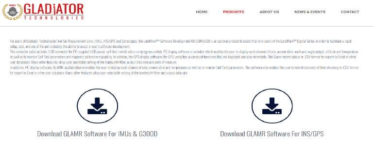
958-00006-001 Technical User Guide

 Glamr

4.2.1 Installation
The LINX SDM-USB-QS-S module requires that device drivers be installed on the host PC before they can interact. The drivers
tell the PC how to talk to the module. These drivers are for Windows 7, 8, and 10. The set for Windows are the direct drivers,
which offer program functions that allow a custom application to directly control the module through the USB port. The latest
Glamr version can be downloaded from https://gladiatortechnologies.com/software-development-kit/.

To install the Glamr SDK application, run the Glamr setup executable found on the website (Figure 1).
 SIMPLE

 Figure 1. Website Glamr download page.

Follow the prompts to install the SDK device drivers as well as the Glamr software (Figure 2).

 Figure 2. Glamr prerequisite installations

Rev. A Copyright © 2021 Gladiator Technologies – Proprietary 7

958-00006-001 Technical User Guide

 ATTENTION: Do NOT use the FTDI device driver that Windows 10 provides. It does not work with the LINX product even
 though they are using the FTDI parts. The PID was changed so it is unique.

Installing Glamr will place a shortcut to the application on the desktop and in the Start Menu.

 Figure 3 Glamr shortcut locations

The default Glamr installation directory is:

C:\Program Files (x86)\Gladiator Technologies

In addition to these shortcuts, the installation will also place a “Glamr.ini” file into:

C:\Users\”username”\AppData\Roaming\Gladiator Technologies\

 NOTE: Plug the connector cable into the USB port before you turn the device power on to avoid Windows loading as a
 mouse driver.

Rev. A Copyright © 2021 Gladiator Technologies – Proprietary 8
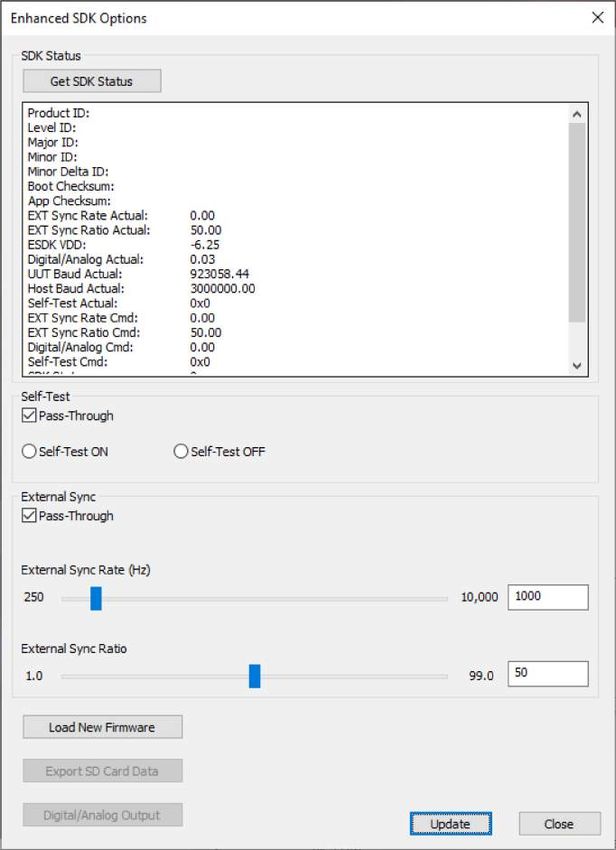
958-00006-001 Technical User Guide

4.2.2 USB Converter Box and Accessories
Contained in the Software Development Kit is a complete RS-422/485 to USB Converter box, which may include a Self-Test
button. The USB Converter box uses USB power to operate (+5 V standard). Some USB Converter boxes may have yellow
(external sync input) and gray (signal ground) banana jacks for applying an external sync signal (Fig. 14). See section Self-
Test in Glamr.

A RS-422/485 to USB converter module is also included.

To accommodate the higher baud and message rates that VELOX® affords us, a new SDK was developed to help with initial
system evaluation and unit configuration. The SX2 SDK allows the host PC to communicate with a connected unit (UUT)
configured at up to 7.5 Mbaud, even though the maximum PC serial port baud rate is only 3.0 Mbaud.

The SX2 SDK communicates with a host PC and Glamr via a serial port at a fixed baud rate of 3.0 Mbaud. On power-up, the
SX2 SDK will automatically detect the baud rate of the UUT and begin relaying the UUT messages to the host PC at 3.0
Mbaud.

Note: The SX2 SDK part number should match SDK-SX2-XXX.

4.2.3 Connecting to Glamr
With the latest Glamr version installed (101.2.81.24 or later), connect the UUT to the SX2 SDK and connect the SDK to the
PC via the included USB cable. Power the SX2 SDK and then run the Glamr software.

Glamr will begin searching for messages from the SX2 SDK. Once connected, messages will begin streaming to the display.
The SX2 SDK options can now be accessed by going to the “SDK Options” menu and selecting “SX2 SDK Options” (Figure 4).

The SX2 SDK can be queried for device status information, can generate a Self-Test signal for the UUT, and can generate an
external sync signal for the UUT. These options only configure the SX2 SDK itself and not the UUT settings. The
SX2 SDK options are volatile and will not persist between power cycles.

Rev. A Copyright © 2021 Gladiator Technologies – Proprietary 9
958-00006-001 Technical User Guide

 The status displays configuration information about the
 SDK and the UUT when queried.

 The Self-Test signal can be configured in a pass-
 through mode for an external driver, or it can be driven
 by the SDK itself.

 The external sync signal can be configured in a
 pass-through mode for an external driver, or it
 can be driven by the SDK.
 Th ESDK ill t t f 250H t 10kH ith

 Figure 4. SX2 SDK options menu in Glamr.

Rev. A Copyright © 2021 Gladiator Technologies – Proprietary 10
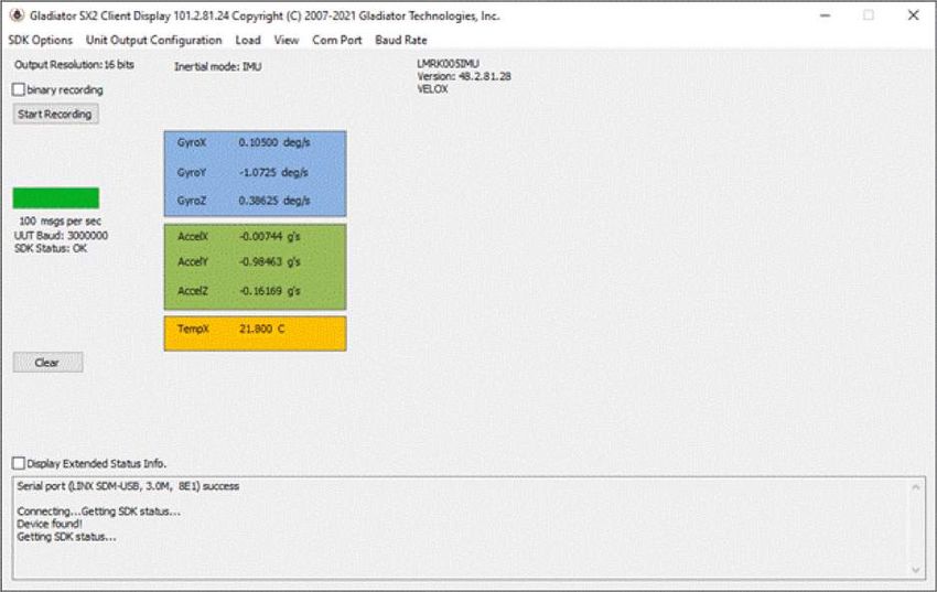
958-00006-001 Technical User Guide

4.2.4 Running Glamr
With Glamr successfully installed, connect the SDK converter box to a unit and to the host PC. Power-on the SDK converter
box and run the Glamr software. A window will appear as in Figure 5.

 Figure 5. Glamr screen with SX2 SDK connected.

Only one instance of Glamr should be open at a given time. Always make sure there is only one instance open on the Windows
task bar. If there are multiple instances of Glamr open, a COM port error will appear when the user tries to interact with the
unit.

Rev. A Copyright © 2021 Gladiator Technologies – Proprietary 11
958-00006-001 Technical User Guide

Initially, Glamr assumes that an SX2 SDK is connected and will attempt to communicate with the SX2 SDK. This can be
observed in the message log output:

 1
 2
 3
 4

 Figure 6. Glamr message log with ESDK running

The messages in the figure above describe the following:
 1. The PC serial port connects to the LINX interface (RS-485-to-USB) at 3.0 Mbaud
 2. Glamr queries the SDK for the SDK status message
 3. Glamr detects messages coming in from a connected unit
 4. Glamr queries the SDK for the SDK status message

If the “SDK Status” displays “OK” in the main Glamr window, then the SX2 SDK was detected by Glamr, otherwise the status
will display “N/A” (Figure 7). A status of “N/A” will happen if an older (legacy) SDK is used, or if the status cannot be read.
In the latter case, please ensure all cables are properly connected and the device is powered-on.

 Figure 7. Glamr displaying an SDK status of “OK” after detecting the SX2 SDK

Rev. A Copyright © 2021 Gladiator Technologies – Proprietary 12
958-00006-001 Technical User Guide

4.2.5 Special Device Driver Settings
For windows to reliably receive messages at high rates (> 1kHz) a small configuration change must be made to the device driver
settings.
Open the Windows Device Manager and expand the Ports (COM & LPT) section. Right-click on the device labeled “LINX SDM-
USB-QS-S” and select “Properties.” Open the “Port Settings” tab and then click the “Advanced” button.

 Figure 8. Device Manager LINX-SDM-USB-QS-S port Properties

Rev. A Copyright © 2021 Gladiator Technologies – Proprietary 13
958-00006-001 Technical User Guide

Now change the Latency Timer drop-down setting to 1 msec (from the default 16 msec). Select OK and apply all changes. This
setting is necessary for the Windows PC to receive message data at higher message rates (>1 kHz) without buffer errors.

 Figure 9. Advanced Settings for COM port Latency Timer

Turn on the power switch on the USB Converter box and you should see data appear in the Glamr window. You should be able
to move the sensor with your hand and see changes in rate and acceleration for each axis located on-screen. To see rapid
change, the record function will capture real time data without the filtering effect of the Glamr display.

Rev. A Copyright © 2021 Gladiator Technologies – Proprietary 14
958-00006-001 Technical User Guide

4.2.6 Select Applicable Baud Rate
The unit baud rate needs to be at least 20% higher than the message rate times the number of bits per message so that the
UUT may still receive commands from the PC. Note that the serial port is half-duplex, so communication between UUT and
host can only go one way. Here is a guideline of the relationship between baud rates and message rates:

 Serial Baud Rate →
 Message Output Rate (Hz) 115200 921600 1.5 M 3.0 M 6.0 M 7.5 M Bits/second

 ↓
 100 Yes Yes Yes Yes Yes Yes 19800
 200 Yes Yes Yes Yes Yes Yes 39600
 500 * Yes Yes Yes Yes Yes 99000
 1000 Yes Yes Yes Yes Yes 198000
 2500 Yes Yes Yes Yes Yes 495000
 5000 Yes Yes Yes Yes 990000
 6000 Yes Yes Yes Yes 1188000
 (Assumes: 198 bits/msg) 10000 Yes Yes Yes 1980000

*Note that 500 Hz Data Mode at 115,200 baud is a special case. In this data mode and baud rate, the bits/second is below
the 20% threshold requirement and therefore requires additional steps to change the UUT to other data modes. When
changing to another appropriate data rate (i.e. 100 Hz, 200 Hz), Glamr will prompt the user to cycle power on the UUT as in
Figure 10.

 Figure 10. Cycle power warning

After power cycling the UUT, the unit will resume normal functionality.

 Figure 11. Baud Rate menu

Rev. A Copyright © 2021 Gladiator Technologies – Proprietary 15
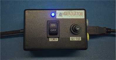
958-00006-001 Technical User Guide

4.2.7 Self-Test in Glamr
Some Gladiator sensors include a Self-Test feature. With the SX2-series, the user can initiate Self-Test in several ways:

 1. With the button found on the USB converter box that is included in the SDK (Figure 12)

Press the button to activate a Self-Test of the sensors. The Glamr display will now show “Self-Test” is activated while also
showing the data outputs. This message can be seen within the Extended Status display. You should see a delta change in
the X, Y, and Z sensor outputs per the data sheet when Self-Test is initiated.

Refer to the device datasheet to see typical activated sensor values.

 Figure 12. USB Converter Box Power, Self-Test Button, Ext Sync Jacks

 2. Through the “SX2 SDK Options” dialog when using an SX2 SDK

The SX2 SDK can generate a discrete (3.3V logic) Self-Test signal internally and send this to the UUT.
This emulates pressing the Self-Test button on a standard SDK converter box.

 3. Through a Built-In-Test command that can be sent via Glamr

The SX2-series of devices have a Built-In-Test (BIT) feature that can actuate the Self-Test procedure in the UUT firmware.
Glamr can send a device command to enable/disable the internal Self-Test feature.

This is necessary for device configurations that do not provide a Self-Test pin on the package.

Rev. A Copyright © 2021 Gladiator Technologies – Proprietary 16
958-00006-001 Technical User Guide

4.2.8 Setting Output Configuration Options
Glamr enables the user to quickly adjust the UUT message rate, sensor bandwidths, and senor output resolution. These
features can be found in the “Unit Output Configuration” menu.

Before these settings can be changed, the current device settings must be retrieved from the connected unit. This is
accomplished by selecting “Retrieve Configuration” under the “Unit Output Configuration” menu as shown in Figure 13.

 Figure 13. Glamr Retrieve unit Configuration option

Once Glamr completes the device configuration retrieval, these options will be enabled.

Rev. A Copyright © 2021 Gladiator Technologies – Proprietary 17
958-00006-001 Technical User Guide

 Set Message Rate
Raising or lowering the message rate determines how frequently messages are sent from the unit to the host. Lower rates
will benefit from additional sample averaging.

The maximum message rate is determined by the message data, data format, and baud rate. The standard maximum message
rate is 5 kHz, and 10 kHz with VELOX® Plus enabled. The minimum message rate is fixed at 10 Hz.

The user can also specify a manual message rate (VELOX® Plus only) in the range of 10 Hz to 10 kHz.

This setting is non-volatile and will persist in unit memory after power-cycling.

 Figure 14. Selecting message rate options for standard devices

Rev. A Copyright © 2021 Gladiator Technologies – Proprietary 18
958-00006-001 Technical User Guide

 Set Bandwidth
Gladiator Technologies offers the user the capability to set bandwidth filtering in permanent memory. The user can set the
bandwidth cutoff frequency in the range of 150 Hz to 600 Hz in 50 Hz increments. VELOX® Plus enabled devices support
cutoff frequencies up to 600 Hz. Otherwise, the maximum cutoff frequency is 350 Hz.

 Figure 15. Selecting sensor bandwidth for standard devices

The sensor cutoff frequency slope (filter order) can also be adjusted. Please contact Gladiator Technologies support for more
information.

Rev. A Copyright © 2021 Gladiator Technologies – Proprietary 19
958-00006-001 Technical User Guide

 Set Output Resolution
Gladiator Technologies devices default to 16-bit LSB resolution for their sensor outputs but provide higher resolutions as well.
This option is user selectable, and the resolution may be changed to 24-bit or 32-bit. The detailed recommended LSB
resolution settings for your device can be found in the Gladiator Technologies SX2 Software Reference Manual.

 Figure 16. Output Resolution selections

 Figure 17. LSB resolution table

Rev. A Copyright © 2021 Gladiator Technologies – Proprietary 20
958-00006-001 Technical User Guide

 Data Recording Feature
Glamr also has a data record feature that captures data streaming from the UUT and puts it into a CSV format. This enables
the user to easily view these data files in Excel or database format. The user should click the Start Recording button (Figure
18) to initiate the data record function.

 Figure 18. Data Recording button

Rev. A Copyright © 2021 Gladiator Technologies – Proprietary 21
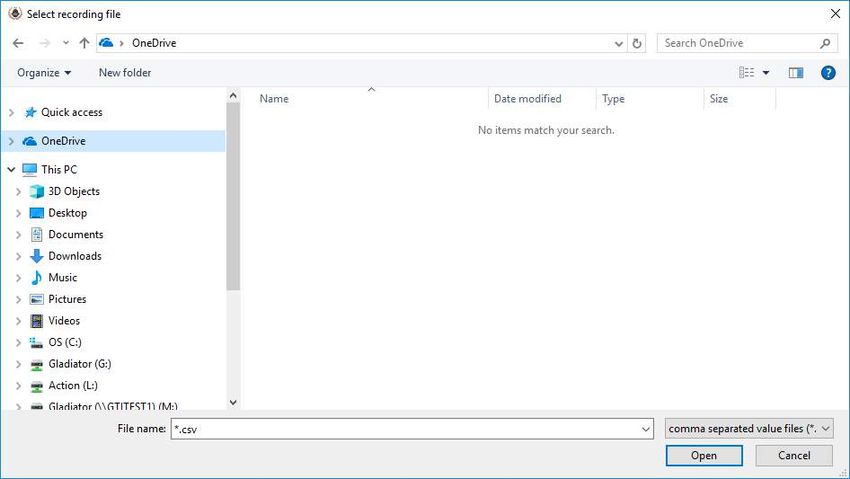
958-00006-001 Technical User Guide

After selecting “Start Recording” Glamr will prompt the user to designate a filename and location before the beginning the
recording. Note that writing to pre-existing filename will not append the data and instead overwrite it with the new
recording. At this prompt, click Open as shown in Figure 19. After the filename and location are selected, click the desired
length of time to record then click OK.

 Figure 19. Saving recorded data files

If a recording time was specified by the user, the time remaining will appear below the Start Record button. To stop
recording, simply click the “Stop Recording” button.

Rev. A Copyright © 2021 Gladiator Technologies – Proprietary 22
958-00006-001 Technical User Guide

4.2.9 Troubleshooting with Messages
If you are experiencing difficulties interfacing the UUT to your system, Glamr can be commanded to display messages sent to
and from the unit in the message window. This is done via the View menu per Figure 20.

 Figure 20. Message options for troubleshooting (View menu)

Rev. A Copyright © 2021 Gladiator Technologies – Proprietary 23
958-00006-001 Technical User Guide

5 PATENT AND TRADEMARK INFORMATION
LandMark® is an official and registered Trademark that identifies Gladiator Technologies brand name for our digital inertial
products. VELOX® is an official and registered Trademark.

6 APPLICABLE EXPORT CONTROLS
LandMark® sensors have been self-classified by Gladiator Technologies with pending Commodity Classification by the U.S.
Department of Commerce under the Export Administration Regulations (EAR), as ECCN7A994 and as such may be exported
without a license using symbol NLR (No License Required) to destinations other than those identified in country group E of
supplement 1 to Part 740 (commonly referred to as the T-5 countries) of the Export Administration Regulations. Items
otherwise eligible for export under NLR may require a license if the exporter knows or is informed that the items will be used
in prohibited chemical, biological, or nuclear weapons or missile activities as defined in Part 774 of the EAR.

7 USER LICENSE
Gladiator Technologies grants purchasers and/or consignees of Gladiator devices a no-cost, royalty-free license for use of the
following software code for use with Gladiator devices. Companies or persons not meeting the criteria as a purchaser or
consignee are strictly prohibited from use of this code. Users in this category wanting to use the code may contact the factory
for other user licensing options.

8 STANDARD LIMITED WARRANTY
Gladiator Technologies offers a standard one-year limited warranty with the factory’s option to either repair or replace any
units found to be defective during the warranty period. Opening the case, mishandling, or damaging the unit will void the
warranty. Please see Gladiator Technologies’ Terms & Conditions of sale regarding specific warranty information.

9 QUALITY MANAGEMENT SYSTEM
Gladiator Technologies’ Quality Management System is third party certified to AS9100 Requirements for Aviation, Space and
Defense (latest revision). To view our current certificate please go to www.gladiatortechnologies.com.

Rev. A Copyright © 2021 Gladiator Technologies – Proprietary 24
958-00006-001 Technical User Guide

10 THEORY OF OPERATION
The LandMark® product line contains several different product variations to meet customer demands. Currently, Gladiator
devices support:

 • Digital 3 Degree of Freedom (DOF) MEMS (Micro Electro-Mechanical System) Gyro that provides delta theta
 information, as well as temperature.

 • Digital 6 DOF MEMS IMU that outputs x-, y-, and z-axis angular rates, x-, y-, and z-axis linear acceleration data, as
 well as temperature.

 • Analog 6 DOF MEMS IMU that outputs x-, y-, and z-axis angular rates, x-, y-, and z-axis linear acceleration data, as
 well as temperature. This is the MRM product line.

 • Digital 6 DOF MEMS Vertical Gyro (VG) that outputs x-, y-, and z-axis angular rates, x-, y-, and z-axis linear
 acceleration data, pitch & roll Euler angles, analog airspeed, as well as temperature.

 • Utilizing Gladiator's proprietary thermal modeling process, these devices are fully temperature compensated, with
 temperature-corrected bias and scale factor, plus corrected misalignment, and g-sensitivity.

Device Features:

 • The internal temperature sensors operate with a 16-bit analog-to-digital converter. These temperature
 measurements are co-located with the x-, y-, and z-axis sensors to enable accurate temperature compensation of
 the sensor outputs.

 • The calibration process measures temperature at a minimum of five set points from -50°C to +85°C and a nine-
 point correction table is generated that identifies temperature-based offsets for each of the IMU data sets.
 Depending upon the variable, up to a 4th order thermal model is used to create a correction model.

 • Though a precision orthogonal mounting block is used in testing LandMark® devices, misalignment error correction
 is also essential in enabling high performance navigation from a MEMS inertial sensor assembly. The calibration
 process also corrects and compensates for internal misalignment errors for all sensors in all three axes.

 • G-sensitivity errors associated with the devices are also modeled and calibrated to correct these performance
 errors associated with acceleration inputs in all three IMU axes.

 • All calibration data is loaded into an internal memory EEPROM enabling a look-up table for thermal modeling
 correction of the outputs during use.

Rev. A Copyright © 2021 Gladiator Technologies – Proprietary 25
958-00006-001 Technical User Guide

Datasheets are available via download on our website. The latest version of all documentation can be found on the Gladiator
Technologies website at www.gladiatortechnologies.com. Copies of the User’s Guides are available upon request at
support@gladiatortechnologies.com.

The SX2-Series software design enables updates to the device. As these software enhancements and upgrades become
available, Gladiator will make them available to our customers.

 Outline and 3D Solid Models
Please visit the product page of your device on the Gladiator website at www.gladiatortechnologies.com. Here you can
download the 3D Solid Model, 2D outline drawing, and other product information. Contact support for additional information.

 Center of Gravity
Some applications need to know the center of gravity (CG) of the package. Please refer to the mechanical drawing for details.

Rev. A Copyright © 2021 Gladiator Technologies – Proprietary 26
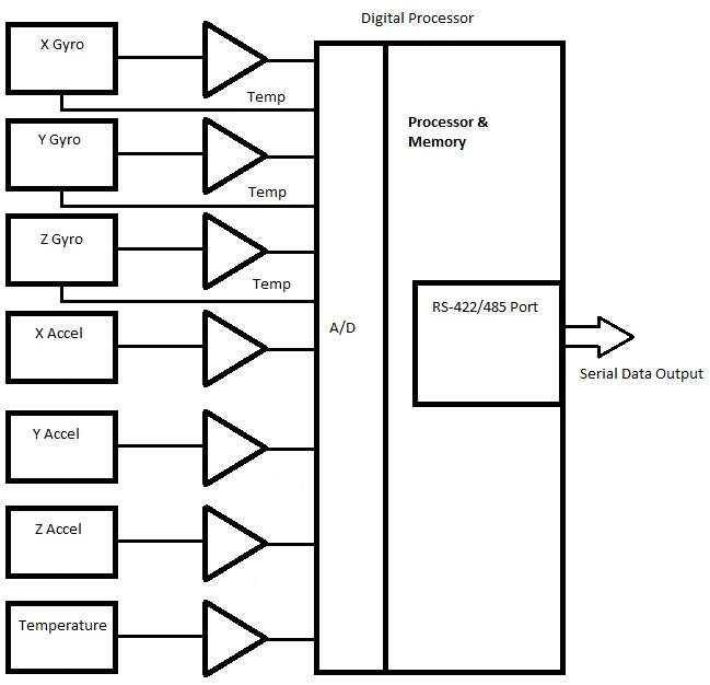
958-00006-001 Technical User Guide

 System Block Diagram
Gladiator sensors have internal functionality which can be represented with a block diagram. Figure 21 is a high-level
representation of a generic Gladiator SX2 inertial product.

 Figure 21. System block diagram

Rev. A Copyright © 2021 Gladiator Technologies – Proprietary 27
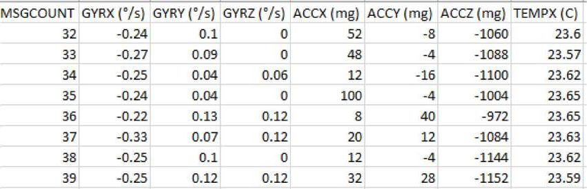
958-00006-001 Technical User Guide

11 MESSAGE PROTOCOL
 Serial Communication Settings

 Parameter Value
 Bits/second: 115200, 921600, 1.5 Mbps, 3.0 Mbps, 6.0 Mbps, 7.5 Mbps, Other
 Start bits: 1
 Data bits: 8
 Parity: Even
 Stop bits: 1

 Figure 22. Serial communication settings values

 Message Packet Format
At power-up, the system enters operational mode using the last commanded mode setting. Please refer to the Gladiator
Technologies SX2 Software Reference Manual for additional information (available upon request:
support@gladiatortechnologies.com)

 Sample Data Format
Figure 23 provides a sample data format output in Excel. The real output includes both the header information and data (see
rows with MSGCOUNT) that contain actual output data. Also included are the multiplier information, averages, and units of
measure for additional clarity.

 Figure 23. Sample data
Please note that when a customer uses the Glamr interface, the program automatically rescales the sensor outputs. This is not
the case for the raw sensor output.

Rev. A Copyright © 2021 Gladiator Technologies – Proprietary 28
958-00006-001 Technical User Guide

11.3.1 Interfacing without Glamr
If you are not using the Glamr interface be aware that the accelerometers require a divide by function. Additionally, you should
use the LSB’s noted per your device datasheet. For example, for a 490°/s rate range sensor, the 16-bit LSB is 0.015 deg/s:

 ( ) 490 /
 = = = 0.015 /
 2 −1 215

The calculations for higher bit resolutions are as follows:

 490 /
 = 0.00006 /
 223

 490 /
 = 0.00000023 /
 231

For a 2000 deg/s gyro at 16-bit:

 2000 /
 = 0.061 /
 215

For temperature, 0.01 °C should be used. Note that in the exponent, one bit is subtracted from the total bit resolution to
account for both positive and negative values (effectively dividing it by two).

Rev. A Copyright © 2021 Gladiator Technologies – Proprietary 29
958-00006-001 Technical User Guide

 External Sync Input
An optional input to some devices is a sync square wave to the External Sync Input pin. This allows the data stream to be
synchronized to an external clock. For example, if the user wants to supply and sync an external GPS to the device, the GPS
can generate a 2.5 kHz square wave, which is sent to the device when the GPS signal is valid. However, any external valid clock
of logic level can be used to synchronize the data.

Refer to the device datasheet to find the maximum external sync frequency and the pin location. Gladiator devices are capable
of single-ended external sync by default, but some unit variations are configured to receive differential signals, as well. This
improves noise immunity for sensitive applications. Please refer to the product page on the website to see if your device is
available with differential external sync.

Note: When an external sync signal is applied, there is no oversampling of the sensor outputs.

11.4.1 Specifications
 • Datasheet-specified clock ± 5% square wave (40% – 60% duty cycle not critical, 50% nominal)
 o Data samples are latched on the rising edge
 o Serial message output is triggered on the falling edge
 • 3.3 V logic is suggested (-0.3 V < “0” < 0.8 V and 2.0 V < “1” < 5.3 V) with respect to signal ground
 • Glitch filter to ignore pulses < 258 ns
 • Input has diode protection to protect the CPU for our two standard input voltage ranges:

 Standard Input Voltage (V) Protected Lower Range (V) Protected Upper Range (V)
 +5 > -0.7 < 10.5

Note that excessive input voltage levels may cause degradation of unit performance.

Please see the SX2 Software Reference Manual for more details about External Sync.

11.4.2 Timing Diagrams
Timing diagrams offer a way to understand and visualize the timings and relationships between different signals of the device.
Your specific device timing diagram can be found on the Gladiator website or by contacting Gladiator support.

Rev. A Copyright © 2021 Gladiator Technologies – Proprietary 30
958-00006-001 Technical User Guide

12 SUMMARY OF TEST METHODS
Units are continuously powered-on, tested at ambient (around 23°C), and data is typically collected at 100 Hz. There are
several tests where the data rate is increased for greater resolution. For unit-specific specifications, please see the datasheet
for your device. The standard temperature range is from -50°C to +85°C.

 Calibration
From a default setting for each product configuration, the initial scale factors, biases, and misalignments are calculated from -
50°C to +85°C and applied to the unit as a starting point for the rest of testing.

 Environmental

12.2.1 Sensor Validation
All sensors are checked for ARW/VRW and bias over temperature performance (including hysteresis).

12.2.2 Shock
Units are placed on a shock hammer to ensure there are no loose components in the assembly and that the unit is functional
after the impact. The unit is powered off for this test.

12.2.3 Temperature Cycle
Units are taken from -50°C to +85°C several times to help break-in and acclimate the sensors to the mounting frame.

12.2.4 Burn-In
Units are left unmonitored at +70°C for approximately 50 hours to remove mounting stresses.

12.2.5 Trend
Units are left at +70°C to monitor any bias drifts in the sensors.

12.2.6 Sensor Saturation
Units are rotated quickly to verify that the gyroscopes saturate to their respective maximum value on each axis. Units are then
placed on a shock fixture with an external reference piezo accelerometer to verify correct accel saturation.

Rev. A Copyright © 2021 Gladiator Technologies – Proprietary 31
958-00006-001 Technical User Guide

 Random and Sine Vibration

12.3.1 Random Vibration
The unit is subject to random frequencies with an energy total contained in the vibration profile up to 15gRMS, depending on the
customer application (see datasheet). The delta shift for each device is measured before and after the run. Also measured
during vibe are the Vibration Rectification Coefficients (VRC) of the unit. This is also used to validate the g-sensitivity correction
on the gyros via the accels.

12.3.2 Sine Vibration Test
The unit is subject to a sine sweep of various frequencies from 30 Hz to 3000 Hz and delta shifts are calculated before and
after the run. The total energy in the test profile is up to 15g’s peak. Also measured during vibe is the VRC of the unit. This is
also used to validate the g-sensitivity correction on the gyros via the accels.

 Rate Linearity
Some Gladiator products require additional testing to accurately calibrate the proper scale factors. Each axis of the unit is
tested for proper gyro cross-coupling and misalignment, then corrected via additional runs. This is performed on a highly
accurate rate table capable of spinning up to the full range of 2000 degrees/second. Ambient scale factors are also calculated
and carried forward.

 Thermal
The unit is tested from -50°C to +85°C at a minimum of five set points to begin tuning the correction model. A second order
model is applied to scale factors and biases for all sensors.

 Bias and Scale Factor Over Temperature (Verify)
The temperature calibration process measures temperature at a minimum of 10 set points from -50°C to +85°C at a slew rate
of approximately 1-2°/minute. Depending on the variable, up to a 4th order thermal model is used to create a correction model.
This dials in scale factors and biases over the temperature range of the test. Residuals (PPM error) are calculated from the
thermal coefficient scale factor deviation from the model.

Rev. A Copyright © 2021 Gladiator Technologies – Proprietary 32
958-00006-001 Technical User Guide

 ATP (Acceptance Test Procedure)

12.7.1 Rate Spin
The unit is mounted on an orthogonal test fixture and spun at about half of the full-scale rate range. Rate scale factors and
device misalignments are corrected.

12.7.2 IMU Tumble
The unit is mounted on an orthogonal test fixture and placed in ± 1g and ± 0g in this test. During this test both the biases and
g-sensitivity are measured.

 FAST-TOT
Like TOT, this test is at 3°C/min in slew rate over the full temperature range of -50°C to +85°C. This is used to create a
preliminary model which the longer TOT validates and applies final corrections. The unit is powered off then turned on and data
is recorded for a short period.

 Turn-On to Turn-On over Temperature (TOT)
This test is performed only if determined it is beneficial to your specific application. The unit is powered off until a temperature
set point is reached. The profile runs over an entire temperature cycle from -50°C to +85°C with set points every 5°C. At
each set point, the unit is turned on and data is recorded for approximately 30 seconds. This simulates and corrects for any
turn-on bias over the temperature range of the device.

 Bias Turn-On from a Cold Start (Long Run)
Test conditions assume a unit has been powered off for a minimum of at least five minutes and then data is taken at ambient
temperature from initial power-on to determine sample turn-on transient performance (25 minutes). It should be noted that
most of the turn-on transient occurs during the initial two minutes after power-on and after that it essential performs near the
specified Bias In-Run performance level.

 Bias In-Run
The unit is placed on an orthogonal test fixture. Then the bias of the accelerometers and gyroscopes are measured at 1 Hz
average. After a five-minute warm-up period, the data is taken for five minutes at ambient temperature. The test conditions
should be similar to what a user should likely have during initial setup approximately within five minutes after turn-on.

Rev. A Copyright © 2021 Gladiator Technologies – Proprietary 33
958-00006-001 Technical User Guide

 Angle Random Walk and Allan Deviation
The unit is mounted on a flat fixture and is turned on and warmed up for 30 seconds. Data is captured at 200 Hz data rate for
30 seconds. The white noise due to angular rate is measured. ARW is typically expressed in our datasheets in degrees per
second per square root hertz (°/sec/√Hz), which is standard for most MEMS devices. However, our performances are now
commensurate with higher performing small open loop FOGs and small RLG’s, so we also denote ARW in degrees per square
root hour (°/√h).

 Velocity Random Walk and Allan Deviation
The unit is mounted on a flat fixture and is turned on and warmed up for 30 seconds. Data is captured at 200 Hz data rate for
30 seconds. Gladiator measures the velocity error accumulating with time, due to white noise in acceleration. VRW is typically
expressed in our datasheets in milli-g per square root hertz (mg/√Hz), which is standard for most MEMS accelerometers.
However, our performances are now approaching higher performing quartz-based servo accelerometers, so we also denote
VRW in meters per second per square root hour ((m/s)/√h).

 Ambient Power Switching TOT (APSTOT)
Data is captured at 200 Hz data rate. Test conditions assume a unit has been powered off for a minimum of at least five minutes
and then data is taken from initial power-on and averaged over two minutes to determine initial offset bias and repeated for
five cycles to determine sample turn-on to turn-on repeatability performance.

 Power Supply Sensitivity (PSS)
Sensor biases and unit current draw are monitored via 15 second samples over multiple set points spanning the input voltage
range. At each set point, there is a short pause before recording to reduce the impact of any transient response. This test
ensures that the unit is functioning properly at any appropriate input voltage level.

13 MOUNTING
Mounting for the device accommodates both metric and U.S. mounting screws. Mount the unit to a flat surface with 4ea 8/32
screws (U.S.) or 4ea M4 metric stainless-steel screws. The minimum torque requirement is 32 in/oz. Be sure that the surface
that you are mounting to is as clean and as level as possible to eliminate potential alignment errors. Adequate mounting to a
surface should fall within a flatness of +/- 0.001” or +/- 0.025 mm.

Failing to mount the unit in this fashion can result in unaccounted stress in the sensors and therefore may affect data output.
Gladiator Technologies strongly encourages the user to mount the unit correctly in the described manner to ensure proper
functioning.

Rev. A Copyright © 2021 Gladiator Technologies – Proprietary 34
958-00006-001 Technical User Guide

14 OPERATION AND TROUBLESHOOTING
 Technical Assistance
Please contact the factory or your local Gladiator Technologies sales representative's office for technical assistance.

 Technical Support
 Gladiator Technologies
 Attn: Technical Support
 8022 Bracken Place SE
 Snoqualmie, WA 98065 USA
 Tel: 425.363.4180
 Email: support@gladiatortechnologies.com
 Web: http://www.gladiatortechnologies.com/representatives/

 Authorized Distributors and Technical Sales Representatives
If you need additional assistance, please contact your local distributor and/or the factory for further technical support:

http://www.gladiatortechnologies.com/international-customers/

Rev. A Copyright © 2021 Gladiator Technologies – Proprietary 35
958-00006-001 Technical User Guide

15 REVISION HISTORY
 Rev Date Description Page Number(s)
 A 1/12/2021 Initial document creation. -

Rev. A Copyright © 2021 Gladiator Technologies – Proprietary 36
You can also read