Ultrasonic Assisted Turning of Al alloys: Influence of Material Processing to Improve Surface Roughness - MDPI
←
→
Page content transcription
If your browser does not render page correctly, please read the page content below
Article
Ultrasonic Assisted Turning of Al alloys: Influence of
Material Processing to Improve Surface Roughness
Hélder Puga 1, * , José Grilo 1 and Vitor H. Carneiro 2
 1    CMEMS - UMinho, University of Minho, Campus of Azurém, 4800-058 Guimarães, Portugal;
      jl.coelho.grilo@gmail.com
 2    MEtRiCS – Mechanical Engineering and Resource Sustainability, University of Minho, Campus of Azurém,
      4800-058 Guimarães, Portugal; d6705@dem.uminho.pt
 *    Correspondence: puga@dem.uminho.pt; Tel.: +351-253-510-220

 Received: 21 March 2019; Accepted: 18 April 2019; Published: 19 April 2019

 Abstract: Ultrasonic machining has been used over a decade to enhance the surface finishing and
 overall processing characteristics of conventional technologies. The benefits that are usually associated
 to this approach generate an increasing interest in both academic and industrial fields, especially
 in the turning operation due to its simple application. In this study, ultrasonic assisted turning
 is used to study the effect of intermittent tool contact on the surface quality of cast and wrought
 aluminium alloys. The resulting surface roughness and topography plots were evaluated through
 a three-dimensional (3D) optical profilometer. Additionally, stereo microscopy and detailed by
 scanning electron microscopy analyzed chip shape and morphology. The experimental results show
 that the appropriate use of an ultrasonic intermittent tool can improve the superficial quality up to
 82% and reduce the maximum peak height by 59 % for a 0.045 mm/rev feed rate. When the feed
 rate is increased to 0.18 mm/rev, the surface roughness may be enhanced by 60% and the maximum
 peak height reduced by 76%. Furthermore, due to the introduction of a distinct cutting mechanism,
 the traditional chip shape is modified when the ultrasonic tool excitation is applied. A model is
 suggested to explain the chip growth and the fracture behaviour.

 Keywords: ultrasonic assisted turning; surface roughness; topography; chip morphology

1. Introduction
      Ultrasonic technology, as a way of assisting manufacturing processes, has been used for over a
decade [1]. The first implementation, denominated ultrasonic machining (USM), worked on a similar
basis to abrasive water-jet machining. The abrasive slurry was fed to one end of the ultrasonic tool [2]
and, through displacement amplifications using a sonotrode, the tool would machine profiles while
the flowing fluid cleans any particles that are released from the operation [3].
      The applicability of this technology has expanded to other processes due to the current evolution
of this technique (e.g. turning, milling, drilling, forming, and others [4–8]). Overall, ultrasonic
assisted machining (UAM) can be characterized as the superimposition of ultrasonic vibration onto a
conventional tool that is used in machining processes [9]. Additionally, the motion is directly applied
to the cutting tip or workpiece [10–12].
      In UAM technologies, particularly in the case of turning, the cutting process becomes an
intermittent procedure that separates the tool insert from the workpiece through micro-scaled
high-frequency vibration. This, in turn, helps to dissipate the heat generated in the cutting process.
When compared to conventional turning, UAT generates a more stable process, resulting in lower
reaction loads, tool wear, and an enhanced surface finish of the workpiece [13,14].

Surfaces 2019, 2, 24; doi:10.3390/surfaces2020024                             www.mdpi.com/journal/surfaces
Surfaces 2019, 2, 24                                                                                          1 of 10

 accuracy
 Surfaces
            of2cutting, disturbs the workpiece finishing, decreases the metal cutting rate, and reduces2
      An2019,  FOR PEER REVIEW
           inconvenient   restriction in surface finishing, as a consequence of equipment vibration,
 tool lifetime. Soleimanimehr et al. [15] reported that UAT reduced 35% of the diametrical error in the
characterizes the conventional turning (CT) cutting process. This also has negative effects on the
 workpiece. When the appropriate frequency is used, the users can benefit from the use of UAT [16],
accuracy of cutting, disturbs the workpiece finishing, decreases the metal cutting rate, and reduces
 especially in terms of surface quality [17] and tool wear reduction [18,19]. Additionally, ultrasonic
tool lifetime. Soleimanimehr et al. [15] reported that UAT reduced 35% of the diametrical error in the
 assisted turning (UAT) is particularly useful when the material properties (e.g. ductility, high tensile
workpiece. When the appropriate frequency is used, the users can benefit from the use of UAT [16],
 strength, micro-hardness, grain orientation, etc.) may change the overall machinability [20].
especially in terms of surface quality [17] and tool wear reduction [18,19]. Additionally, ultrasonic
       The current study presents an approach of applying ultrasonic vibration during the turning of
assisted turning (UAT) is particularly useful when the material properties (e.g. ductility, high tensile
 Al alloys, thus, generating the UAT process. The particular innovation of this process is the
strength, micro-hardness, grain orientation, etc.) may change the overall machinability [20].
 implementation of a resonant frequency tracking system that allows for a direct adaptation to
      The current study presents an approach of applying ultrasonic vibration during the turning
 stiffness changes in the system. Thus, the cutting process remains in optimized resonant conditions
of Al alloys, thus, generating the UAT process. The particular innovation of this process is the
 and prevents the operation in non-resonant states.
implementation of a resonant frequency tracking system that allows for a direct adaptation to stiffness
       This work studies the influence of feed rate in the overall surface quality and roughness when
changes in the system. Thus, the cutting process remains in optimized resonant conditions and prevents
 the conventional tool is excited in the described conditions. Additionally, the influence of material
the operation in non-resonant states.
 properties, such as yield strength, toughness, and overall deformation mechanisms, are correlated
      This work studies the influence of feed rate in the overall surface quality and roughness when
 with the overall chip formation mechanism that UAT promotes.
the conventional tool is excited in the described conditions. Additionally, the influence of material
properties,
 2. Materialssuch
               andas  yield strength, toughness, and overall deformation mechanisms, are correlated
                    Methods
with the overall chip formation mechanism that UAT promotes.
 2.1. Experimental Description
2. Materials and Methods
       The turning experiments (Figure 1a) were performed in dry condition while using a
2.1.  Experimental
 conventional        Description
                  lathe    (EFI DU25, EFI, Trofa, Portugal). The Al alloy workpieces are given an
 anticlockwise
      The turningrotation,   while the
                     experiments        tool 1a)
                                    (Figure   vibration  with UAT in
                                                  were performed    is aligned  with the
                                                                       dry condition      cutting
                                                                                        while usingdirection  (Figure
                                                                                                     a conventional
 1b). The   lower  side  of the insert is used   as the active cutting  edge, which    safely projects
lathe (EFI DU25, EFI, Trofa, Portugal). The Al alloy workpieces are given an anticlockwise rotation,    the resulting
 chip away
while         from
        the tool     the user.
                 vibration      Figure
                              with  UAT1a    shows the
                                          is aligned     experimental
                                                      with               setup and(Figure
                                                            the cutting direction    it identifies each
                                                                                             1b). The    component
                                                                                                       lower  side of
 as the  following:   (1) Insert, (2) Workpiece,    (3) Acoustic radiator  (horn),  (4) Transducer,   (5) Support
the insert is used as the active cutting edge, which safely projects the resulting chip away from the user.        of
 UAT   system,   and   (6) Spindle.   MPInterconsulting     manufactures    the ultrasonic  components
Figure 1a shows the experimental setup and it identifies each component as the following: (1) Insert,      (Le Locle,
 Switzerland).
(2) Workpiece, (3) Acoustic radiator (horn), (4) Transducer, (5) Support of UAT system, and (6) Spindle.
MPInterconsulting manufactures the ultrasonic components (Le Locle, Switzerland).

                       Figure1.1. (a)
                       Figure      (a) Experimental
                                       Experimental setup.
                                                     setup. (b)
                                                            (b) Cutting
                                                                Cutting contact
                                                                        contact during
                                                                                during turning
                                                                                        turning process.
                                                                                                process.

2.2.
2.2. Specification
     Specification of
                   of the
                       the Machining
                           Machining Process
                                     Process
      The
      The tool
           tool insert
                 insert was
                         was selected
                              selected for
                                        for the
                                             the finishing
                                                  finishing and
                                                            androughing
                                                                roughingoperations
                                                                           operations at
                                                                                      at medium
                                                                                         medium depths
                                                                                                  depths of
                                                                                                          of cut
                                                                                                              cut
and  feed  rates.  The  interrupted
 and feed rates. The interrupted      cuts  at high   metal  removal rates and  the type of material (Al alloys)
                                               high metal removal rates and the type of material (Al alloys)
were
 were also
       also considered
             considered in inthe
                               theinsert
                                    insertselection.
                                            selection. A A Micrograin
                                                           Micrograin Cemented
                                                                       Cemented Carbide
                                                                                    Carbide CVD-coated
                                                                                             CVD-coated insert
                                                                                                          insert
(reference                                                                                         ◦ nose angle,
 (referenceCCMT120408PM,
             CCMT120408PM,Sandvik, Sandvik,Stockholm,
                                              Stockholm,Sweden),
                                                            Sweden),with
                                                                     withaa0.8
                                                                             0.8 mm
                                                                                 mm radius
                                                                                     radius and
                                                                                            and 80
                                                                                                80°  nose
was
 wasselected
      selectedtotoperform
                   performthetheturning
                                  turningexperiments.
                                            experiments.
      According to Figure 1a, the tool insert (1) is directly attached to the horn (3) through a bolt,
 which, in turn, is fixed to the transducer (4). The piezoelectric transducer (electrical power up to 3000
 W in continuous current) is powered by an ultrasonic generator that is based on the MMM (Multi-
 Mode,-Frequency,-Modulated) Technology. This component can produce high efficiency active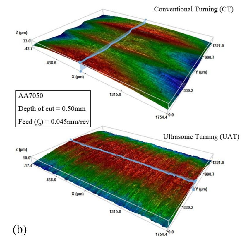
Surfaces 2019, 2, 24                                                                                2 of 10

     According to Figure 1a, the tool insert (1) is directly attached to the horn (3) through a bolt,
which, in turn, is fixed to the transducer (4). The piezoelectric transducer (electrical power up to
3000 W in continuous current) is powered by an ultrasonic generator that is based on the MMM
(Multi-Mode,-Frequency,-Modulated) Technology. This component can produce high efficiency active
power in wide-band sonic and ultrasonic vibrations. The ultrasonic generator supplies the required
frequency in the range of 19-21 KHz, which generates an average amplitude of 20 µm for the present
configuration. The ultrasonic equipment is clamped in the booster nodal point and is bolted to an
aluminium structure, which is itself fixed to the lathe (Figure 1a). Thus, all the movements of turning
can be obtained with the same precision as that achieved by the base conventional lathe composition
of equipment.
     For comparison purposes, distinct Al alloys were selected to determine the behaviour of UAT
under different grain morphology, hardness, yield strength, and toughness (i.e. ability to maintain
plastic deformation in the chip). These properties were analysed to determine their impact in the
overall surface roughness of UAT and conventional cutting processes. As such, as-cast Al7Si0.3Mg
(7.44% Si, 0.3% Mg, 0.13% Fe, 0.11% Ti, 0.07% Cu, 0.07% Mn, 0.05% Zn, 0.12% Res., Balance Al) and
wrought AA7050 (5.74% Zn, 2.11% Cu, 1.98% Mg, 0.12% Fe, 0.09% Zr, 0.05% Si, 0.04% Mn, 0.06%
Res., Balance Al) alloys were the workpiece materials used. In addition to these individual materials,
the work was carried out under different values of machining feed rates, as seen in Table 1. The
conventional cut is performed with the same set-up, only without ultrasonic vibration. The first 20
mm length of each sample are machined through conventional turning process, leaving the remaining
20 mm to be cut by the UAT that is superimposed in the tool, as shown in Figure 1b. The selected
parameters and their values were defined by the experience of the authors and selected as the most
suitable for performing this study.

                                    Table 1. Experimental parameters.

                                 Specification                            Value
                         Rotation per minute, N (rpm)                      760
                            Depth of cut, ap (mm)                           0.5
                          Cutting speed, V (m/min)                          60
                            Feed rate, fa (mm/rev)                      0.045; 0.18

      The referred methodology was performed in three distinct samples for each tested material, feed
rate, and tool-excitation combination (a total of 32 samples). To avoid any inherent uncertainty issues,
half of the samples were machined with a UAT-CT order, while the other half were machined with a
CT-UAT order (i.e. the process was inverted). A new insert was used for every test to eliminate any
wear related uncertainty.

2.3. Post-Experimental Surface Characterization
     Posteriorly to the turning process, analysis was carried out using a three-dimensional (3D) optical
profilometer (S-neox, Sensofar, Barcelona, Spain). The vertical scanning interferometry (VSI) mode
characterized the machined surfaces for the CT and UAT samples on both alloys. This allows a
nanometer resolution in the vertical axis. The magnification (DI, 10x) enables the measuring of 1.75
mm × 1.32 mm (1360 × 1024 pixels) areas with a lateral resolution of about 0.7 µm for white light.
Concerning the evaluation of surface quality, an arithmetic average was used as the common ground
between samples, which is expressed through the surface roughness (Ra) value from the Equation (1).
As defined in ISO 4287, l is the sample’s tested length and Z is the height of the profile at a determined
coordinate (x). These values were monitored in a 1.75 mm straight line parallel to the sample turning
axis using the 3D optical profilometer results, where three different observation fields were analyzed in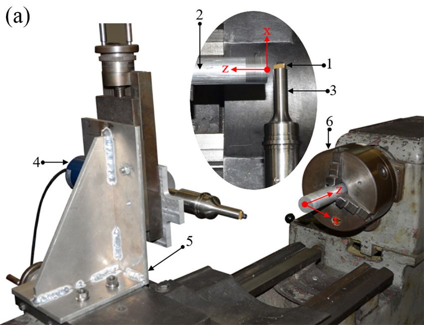
Surfaces 2019, 2, 24 3 of 10
each machined samples. The Maximum Peak Height of Profile (Rz ) was also determined while using
the same data.
1 l
Z
Ra = Z(x) dx (1)
l 0
The2019,
Surfaces morphology
2 FOR PEERof the resulting chip formed during machining process was observed under a 4
REVIEW
stereo microscope that was coupled to an image acquisition system (EZ4 HD, Leica, Wetzlar, Germany).
AGermany). A detailed characterization
detailed characterization of their
of their surfaces was surfaces was
performed performed
using using
a scanning a scanning
electron electron
microscope
microscope
(SEM—S 4100(SEM—S 4100 Hitachi,
Hitachi, Tokyo, Japan).Tokyo, Japan).
2.4.
2.4.Sample
SampleCasting
Castingand
andTesting
Testing
The
TheAl7Si0.3Mg
Al7Si0.3Mgalloyalloywas
was melted
melted inside
inside aa crucible,
crucible,where
whereititwas
washeld
heldononanan isothermal
isothermal state
state (720
(720 ± 5 ◦ C, 15 min) for homogenization. The Al5Ti1B (0.2%mass [21]) and Al10Sr (0.3%mass [22])
± 5 °C, 15 min) for homogenization. The Al5Ti1B (0.2%mass [21]) and Al10Sr (0.3%mass [22]) master
master
alloysalloys were added
were added to the to thetomelt
melt to promote
promote a chemical
a chemical grain refinement
grain refinement and modification
and modification of
of eutectic
eutectic
Si. TheSi. The isothermal
isothermal state
state was wasfor
kept kept for another
another 5 min 5tomin to allow
allow for dissolving
for a full a full dissolving
of theof the master
master alloys,
alloys, after which ultrasound degassed the melt [23] to release entrapped hydrogen.
after which ultrasound degassed the melt [23] to release entrapped hydrogen. This also prevents the This also prevents
the sedimentation
sedimentation of the
of the refining
refining particles
particles [24,25].
[24,25]. Posteriorly,
Posteriorly, the melt
the melt was allowed
was allowed to cooltodown
cool down
(700°C)
(700 ◦ C) and poured into pre-heated (250 ± 2 ◦ C) cylindrical (Ø30 ± 0.5 × 70 mm) steel molds. The
and poured into pre-heated (250 ± 2 °C) cylindrical (Ø30 ± 0.5 × 70 mm) steel molds. The wrought
wrought
AA7050AA7050 alloy wasalloy was obtained
obtained by a commercial
by a commercial rod (Ø30rod h7),
(Ø30where
h7), where
a 70 mm a 70length
mm length section
section wasto
was cut
cut to obtain
obtain the final
the final shapeshape forrequired
for the the required turning
turning experiment.
experiment.
The
The tensile specimens were manufactured from thecasted
tensile specimens were manufactured from the castedandandwrought
wroughtcylinders
cylindersaccording
accordingISO ISO
6892.
6892.FiveFivespecimens
specimensfor foreach
eachalloy
alloywere
weretested
testedononananINSTRON
INSTRON8874 8874universal
universaltesting
testingequipment
equipment
(Instron,
(Instron,Norwood,
Norwood,Massachusetts,
Massachusetts,USA) USA)onondisplacement
displacementcontrol
control(0.1
(0.1mm/s).
mm/s).TheTheinstant
instantvalues
valuesofof
load and displacement were recorded using a load cell and strain gauge, being posteriorly
load and displacement were recorded using a load cell and strain gauge, being posteriorly converted converted
totoa astress-strain
stress-strain plot.
plot.
3.3.Results
Resultsand
andDiscussion
Discussion
Figures
Figures2 2andand3 3show
showthe average
the averagesurface
surfaceroughness
roughnessand
andmaximum
maximumpeak peakheight
heightofofthe
theCT
CTand
and
UAT samples. Overall, the experimental results suggest a reduction of 55%–82% in terms
UAT samples. Overall, the experimental results suggest a reduction of 55%–82% in terms of surface of surface
roughness
roughness(R(R
a )a)when
whenapplying
applyingUAT.UAT.ItItmay
maybebealso
alsoobserved
observedthat
thatthere
thereisisa a59%–76%
59%–76%reduction
reductioninin
Maximum Peak Height
Maximum Peak Height (R (R ).
z z).
Figure 2. Average surface roughness (Ra ) for the tested materials using feed rate of (a) 0.045 and (b)
Figure 2. Average surface roughness (Ra) for the tested materials using feed rate of (a) 0.045 and (b)
0.18 mm/rev.
0.18 mm/rev.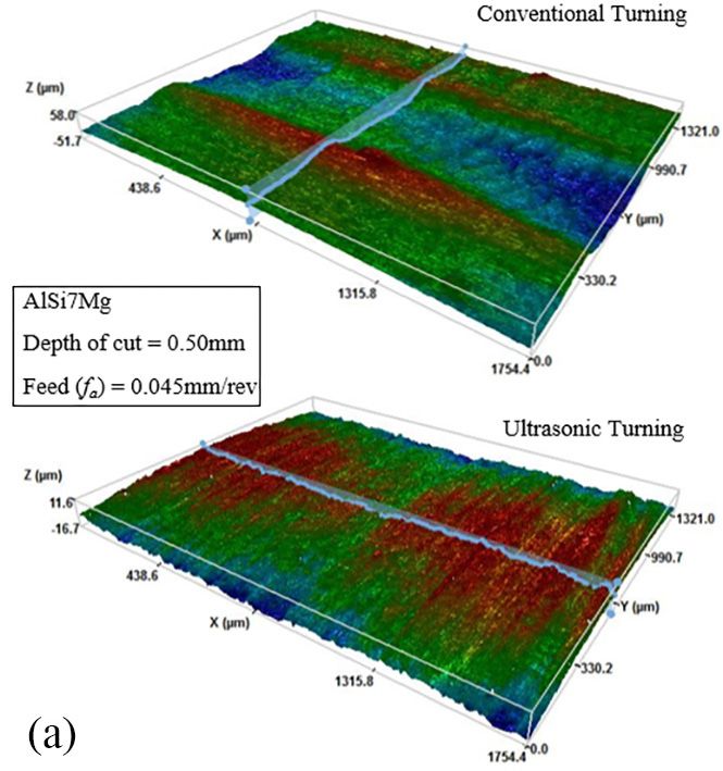
Figure 2. Average surface roughness (Ra) for the tested materials using feed rate of (a) 0.045 and (b)
Surfaces 2019, 2, 24                                                                                        4 of 10
          0.18 mm/rev.

      Figure 3. Maximum height of profile (Rz ) for the tested materials using feed rate of (a) 0.045 and (b)
      0.18 mm/rev.

      During the UAT cutting process, the resonance frequency that is driven by the generator was
20.470 ± 0.005 kHz and 20.205 ± 0.005 kHz, respectively, for the feed rates of 0.18 mm/rev and 0.045
mm/rev. As can be seen, during the ultrasonic assisted machining, the variation in feed rate promoted
a shift in the resonant frequency value. Indeed, with the increasing of external loading as well as due
to some incoherence on the base matrix, the resonant frequency of system varied by 265 Hz when the
feed rate was increased from 0.045 mm/rev to 0.18 mm/rev.
      In fact, as stated by various authors [10,20], a vibration cutting device can report different cutting
behaviour when subjected to distinct conditions. Moreover, according to the same authors, the feed
rate is suggested as the most influential parameter on surface quality. Gao and Sharma [26–28] showed
that the depth of cut seems to have less effect on the surface roughness relative to the feed rate; however,
it has been reported to generate higher cutting loads. Given the influence of the latter in the stiffness of
the overall system, the depth of cut was kept constant to prevent the ultrasonic equipment to operate
on non-resonant states. However, there may be still small stiffness changes in the system during the
cutting process, which slightly change the system resonant frequency (~20 kHz), as stated by other
published studies [29–31]. To correct this resonance shifting, a real-time a Phase Locked Loop (PLL)
resonant frequency tracking system was implemented on the MMM generator (as patented by M.
Prokic [32]).
      According to the results that are presented in Figures 2 and 3, it is clear that the base material
has influence on the quality of machined surface. For the same operations conditions, the average of
surface roughness (Ra ) and maximum peak height (Rz ) for the Al7Si0.3Mg cast alloy are higher than
those that were evaluated for case of the AA7050 alloy. The quality of surfaces machined by UAT
suggest a better homogeneity and repeatability (i.e. lower standard deviation values in Figures 2 and 3)
when compared to conventional machining. Additionally, the introduction of ultrasonic tool-vibration
may be useful in industrial applications in distinct approaches: (i) maintaining feed rate to obtain
machined parts with enhanced surface quality; and, (ii) increase feed rate, while trying to maintain
surface quality, to reduce the machining times.
      The roughness mitigation and enhanced surface quality in UAT is more evident when a lower
feed rate (fa = 0.045 mm/rev) is applied. To better understand the effect of the workpiece material, the
resulting geometry was observed and studied using a 3D surface perfilometer. Figure 4 shows the
topography of sample, as presented in Figures 2a and 3a.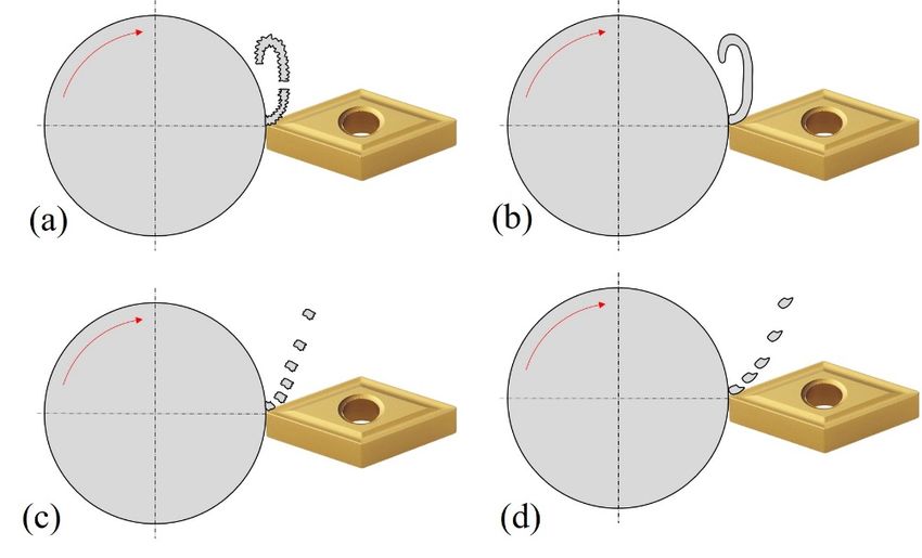
maintain surface quality, to reduce the machining times.
      The roughness mitigation and enhanced surface quality in UAT is more evident when a lower
feed rate (fa = 0.045 mm/rev) is applied. To better understand the effect of the workpiece material, the
resulting geometry was observed and studied using a 3D surface perfilometer. Figure 4 shows the
topography
Surfaces 2019, 2, of
                  24 sample, as presented in Figures 2a and 3a.                                   5 of 10

      Figure4.4. Surface
     Figure              topography(f(faa =
                 Surfacetopography          0.045 mm/rev):
                                          = 0.045 mm/rev): (a)
                                                           (a) Al7Si0.3Mg
                                                               Al7Si0.3Mg sample;
                                                                          sample; and,
                                                                                  and, (b)
                                                                                       (b) AA7050
                                                                                           AA7050 sample.
                                                                                                  sample.

     It may be observed that, while the rough cutting is evidently shown in the traditional process,
there are almost no periodic peaks that can be traced upon using the ultrasonic vibration. These
observations on surface plots are in accordance with other authors [33]. The AA7050 samples in
Figure 4b show a consistent tool path, particularly for the UAT, which resulted in the most homogenous
texture of all the samples. In contrast, the conventional turning Al7Si0.3Mg samples displays damaged
topography. The tool trajectory can be easily detected on the workpiece surface through the ridges
that formed from its plastic deformation [34]. Although, such a detrimental effect is not seen when
UAT is applied. This observation is in accordance with the different standard the deviation values
for UAT that are presented in Figures 2a and 3a, suggesting a close relationship between the material
deformation properties and the UAT performance.
     Figure 5 displays the average stress-strain curves from the tensile tests. It is shown that the alloys
display a distinct behaviour, allowing for the study of contrasting deformation mechanisms. However,
given that they are both Al alloys, they are able to reduce other machining variables that could influence
the results (e.g. friction coefficient, thermal conductivity and expansion, etc.). It may be observed that
the Al7Si0.3Mg alloy displays a relatively prominent plastic domain. This fact is supported by its
higher toughness (T = 1.21 MJ/m3 ) when compared to the AA7050 alloy (T = 0.77 MJ/m3 ). Additionally,
the AA7050 alloy displays fragile behaviour, being observed in the failure without localized necking
and by the yield strength (σy ) values being very close to its tensile strength (σUTS ). Overall, the
contrasting deformation mechanisms between the tested alloys generate different cutting and chip
forming mechanisms for both the CT and UAT conditions.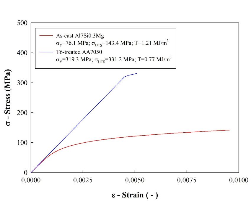
supported by its higher toughness (T = 1.21 MJ/m3) when compared to the AA7050 alloy (T = 0.77
MJ/m3). Additionally, the AA7050 alloy displays fragile behaviour, being observed in the failure
without localized necking and by the yield strength (σy) values being very close to its tensile strength
(σUTS). Overall, the contrasting deformation mechanisms between the tested alloys generate different
cutting   and2,chip
Surfaces 2019,  24 forming mechanisms for both the CT and UAT conditions.                           6 of 10

           Figure 5.
           Figure    Average stress-strain
                  5. Average stress-strain curved
                                           curved of
                                                  of the
                                                     the tested
                                                         tested materials
                                                                materials (Al7Si0.3Mg
                                                                          (Al7Si0.3Mg and
                                                                                      and AA7050).
                                                                                          AA7050).

      Chips were
      Chips    were collected
                      collected and
                                 and analysed
                                      analysed for
                                                 for aa better
                                                        better understanding
                                                               understanding of of the
                                                                                   the UAT
                                                                                       UAT cutting
                                                                                             cutting mechanism,
                                                                                                     mechanism,
(Figure 6) and these results were correlated with the properties that are displayed in According
(Figure   6) and   these results were  correlated with  the properties that are displayed in Figure 5.  Figure 5.
According to the results, Figure 7 illustrates the cutting mechanism and the chip morphologybased
to the  results,   Figure  7 illustrates the cutting  mechanism   and   the chip morphology    that are         on
                                                                                                          that are
the material
 Surfaces 2019, 2and
                  FORturning    processes.
                      PEER REVIEW
based on the material and turning processes.                                                                      7

      Figure6.6.Example
     Figure      Exampleof
                         ofstereo
                            stereomicroscope
                                    microscope(5x(5xmagnification)
                                                     magnification)images
                                                                    imagesofofchip
                                                                               chipmorphology    withfaf=0.045
                                                                                    morphologywith      a=0.045

     mm/rev.
      mm/rev.Al7Si0.3Mg
                Al7Si0.3Mgsample
                            sampleby by(a)
                                        (a)ultrasonic
                                            ultrasonicassisted
                                                       assistedturning
                                                                turning(UAT)
                                                                        (UAT)and and(b)
                                                                                     (b)conventional
                                                                                         conventionalturning
                                                                                                       turning
     (CT).
      (CT).AA7050
            AA7050sample
                    samplebyby(c)
                                (c)UAT
                                    UATand
                                         and(d)
                                              (d)CT.
                                                  CT.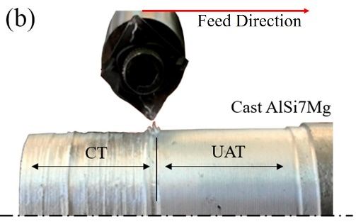
Figure 6. Example of stereo microscope (5x magnification) images of chip morphology with fa=0.045
     mm/rev. Al7Si0.3Mg sample by (a) ultrasonic assisted turning (UAT) and (b) conventional turning
Surfaces 2019, 2, 24                                                                                   7 of 10
     (CT). AA7050 sample by (c) UAT and (d) CT.

       Figure 7. Suggested chip formation during the turning operation: Al7Si0.3Mg sample by (a) UAT and
      Figure
       (b) CT;7.and,
                 Suggested
                     AA7050chip formation
                            sample  by (c) during
                                           UAT andthe(d)
                                                      turning
                                                         CT. operation: Al7Si0.3Mg sample by (a) UAT and
      (b) CT; and, AA7050 sample by (c) UAT and (d) CT.
       The chips from the same process share the similar traits. As depicted in Figure 6b,d, chips from
      The chips
 traditional      from present
               turning    the samethemselves
                                      process share      the similar
                                                    as slightly        traits.
                                                                  longer   andAs    depicted
                                                                                 thicker,       in Figure
                                                                                            followed     with 6b,d,
                                                                                                                smallchips
                                                                                                                         sidefrom
                                                                                                                               burr.
traditional
 As shown turning
              in Figurepresent     themselves
                           7b, Al7Si0.3Mg         as slightly
                                               produced          longer and thicker,
                                                             semi-continuous       chips,followed
                                                                                            whereaswith AA7050 smallinside   burr.
                                                                                                                        Figure   6d
As  shown    in Figure   7b,   Al7Si0.3Mg     produced      semi-continuous       chips,   whereas
 generated a segmented non-homogenous chip. The latter distinguishes from other samples through its     AA7050     in  Figure   6d
generated    a segmented
 smaller radius    curls andnon-homogenous
                                taller sawteeth. The  chip.UATTheprocess,
                                                                   latter distinguishes
                                                                            as exemplified   from   other samples
                                                                                                in Figure     7a,c, showsthrough
                                                                                                                             larger
its smaller
 chip         radius However,
       curl radius.    curls and signs
                                    taller of
                                           sawteeth.
                                              violent tearThetaking
                                                                UAT process,
                                                                       place in asits exemplified
                                                                                      side burrs are   infound
                                                                                                           Figurein7a,c,
                                                                                                                     Figureshows
                                                                                                                               6a,c,
larger  chip  curl radius.   However,     signs   of violent   tear taking   place   in its side
 where Nath and Rahman made similar observations [35]. Analogous to the conventional turning,     burrs   are  found    in Figure
6a,c,
 AA7050where
           chipsNath
                   thatand
                         wereRahman
                                 produced madeby UATsimilar
                                                          are observations      [35]. As
                                                               shorter in length.       Analogous
                                                                                           shown into        the conventional
                                                                                                         Figure    6c,d, the side
turning,  AA7050      chips   that  were   produced      by  UAT    are  shorter   in
 burrs of the commercial alloy are more evenly distributed when compared to the casted length.   As   shown     in  Figure    6c,d,
                                                                                                                       specimen.
the
 Theside
      factburrs
           that theof the   commercial
                      Al7Si0.3Mg      alloyalloy   are more
                                              is more    ductile evenly   distributed
                                                                   than the    AA7050 when         compared
                                                                                           alloy allows      for atomore
                                                                                                                      the casted
                                                                                                                            plastic
specimen.
 deformation Thetofact  that the Al7Si0.3Mg
                    be supported     before the alloy
                                                   overallis more   ductile than
                                                             chip separation             AA7050
                                                                                in the cast    alloy.alloy  allows
                                                                                                       On the    otherforhand,
                                                                                                                           a more
                                                                                                                                the
plastic  deformation     to  be  supported     before   the  overall  chip  separation
 wrought alloy is separated from the workpiece before severe material flow occurs.          in the  cast   alloy.  On   the  other
hand,When
        the wrought     alloythe
               considering     is separated
                                    nature of from     the workpiece
                                                the cutting    mechanism  before   severe
                                                                              of UAT,        material
                                                                                         violent         flowisoccurs.
                                                                                                   rupture        to be expected
 as a result of its imposed vibration. Nevertheless, this does not contribute to worse results when
 compared with CT, as previously seen from the results in Figures 2 and 3. On traditional turning, the
 lamellar segregation is determined by the workpiece mechanical properties, especially the presence
 of plastic deformation. According to the magnifications in Figure 6, this is supported by the plastic
 deformation and toughness of the Al7Si0.3Mg cast alloy. However, with ultrasonic vibration, chip
 morphology implies that the tool’s motion heavily influences its formation, which is in accordance to
 other published studies [36,37].
       As seen from the topography in Figure 4 and the standard deviation in Figures 2 and 3, the casted
 alloy offers relative poor machinability when compared with the wrought alloy while using the same
 process. This may be correlated with the tensile test results in Figure 5. It is shown that the latter
 chip formation is possible when there is an effective plastic domain (as-cast Al7Si0.3Mg), and absent
 where the alloy presents a fragile behaviour (wrought AA7050). This fact may be highlighted by the
 determined toughness values, in which the low toughness that characterizes the AA7050 alloy does
 not allow the referred chip forming effect. To better evaluate the surface of the chips, the SEM images
 from both cutting methods and alloys are analysed, as seen in Figure 8.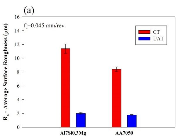
latter chip formation is possible when there is an effective plastic domain (as-cast Al7Si0.3Mg), and
absent where the alloy presents a fragile behaviour (wrought AA7050). This fact may be highlighted
by the determined toughness values, in which the low toughness that characterizes the AA7050 alloy
does not allow the referred chip forming effect. To better evaluate the surface of the chips, the SEM
images from both cutting methods and alloys are analysed, as seen in Figure 8.
Surfaces 2019, 2, 24                                                                                                 8 of 10

      Figure 8. Scanning
                Scanning electron
                         electron microscope
                                  microscope (SEM)
                                              (SEM) images
                                                    images of      morphology with faa ==0.045
                                                           of chip morphology             0.045mm/rev.
                                                                                               mm/rev.
      Al7Si0.3Mg sample by (a) UAT
                                UAT and
                                    and (b)
                                         (b) CT.
                                             CT. AA7050
                                                 AA7050 sample
                                                        sample by
                                                               by(c)
                                                                  (c)UAT
                                                                     UATand
                                                                         and(d)
                                                                              (d)CT.
                                                                                 CT.

      Despite the
      Despite   the casted
                    castedchip
                             chipshare
                                   sharesimilar
                                          similarcurvature
                                                   curvature  shown
                                                                 shown in in
                                                                          Figure   8a,b,
                                                                              Figure      they
                                                                                      8a,b,    differ
                                                                                             they      in the
                                                                                                   differ   in texture  that
                                                                                                               the texture
 originated  from  the  tool-chip  contact.  While   conventional     turning   shows   signs  of
that originated from the tool-chip contact. While conventional turning shows signs of friction andfriction   and  adhesion
 in the secondary
adhesion    in the deformation       zone, UAT surface
                      secondary deformation         zone, UATis differentiated
                                                                     surface is by    its roughnessbyconsistency
                                                                                   differentiated          its roughnessand
 orientation.  The   extruded    alloy (AA7075)     that  was   subjected    to UAT    is characterized
consistency and orientation. The extruded alloy (AA7075) that was subjected to UAT is characterized          by the  scaled
 pattern
by       shownpattern
    the scaled    in Figure  8c. Such
                          shown         a feature
                                   in Figure       can attributed
                                               8c. Such   a feature to  the
                                                                      can    intermittent
                                                                           attributed        contact
                                                                                        to the        of the process
                                                                                                intermittent     contactand
                                                                                                                          of
 lower
the     toughness
     process         (Figuretoughness
               and lower       5). This combination
                                           (Figure 5). results    in the generation
                                                         This combination        resultsofinsmall  superficial cracks
                                                                                              the generation              in
                                                                                                                   of small
 secondary    deformation     area  until the chip   fractures.   In contrast,   chips   from  the  same
superficial cracks in secondary deformation area until the chip fractures. In contrast, chips from the      alloy   that are
 machined
same   alloy by
             thatCT  (Figure
                   are machined8d) have
                                    by CTa (Figure
                                            partially8d)smoother    surface. smoother
                                                          have a partially     It is proposed    thatItaislower
                                                                                           surface.               tool-chip
                                                                                                           proposed     that
acontact
   lower area  induced
          tool-chip       by thearea
                      contact     curvature
                                      induced of by
                                                 thesethechips  favoured
                                                          curvature         these chips
                                                                        of these    unaffected   sections.
                                                                                           favoured     these unaffected
sections.
4. Conclusions
4. Conclusions
     In the present study, an experimental approach was employed to compare conventional (CT) and
ultrasonic
     In theassisted
            present turning
                     study, an(UAT). Overall, the
                                experimental      quantification
                                               approach            of surface
                                                           was employed    to roughness  and the resultant
                                                                              compare conventional    (CT)
chips  analyse the benefit of introducing an ultrasonic   excitation on the tool to machine
and ultrasonic assisted turning (UAT). Overall, the quantification of surface roughness      Al alloys.
                                                                                                   and the
     The experimental results showed that the application and ideal use of the ultrasonic elements and
the surface quality of machining samples are improved up to 56% and are characterized by uniformly
distributed topography. It is shown that this benefit is more noticeable in materials with lower plasticity,
especially when the feed rate is increased. This may be justified by the production of a shorter chip
and the presence of a uniform deformed morphology.
     UAT is shown to be beneficial in terms of surface quality when considering the manufacturing
differences between the casted and commercial extruded alloys. The adopted method is presented
as an accessible approach to obtain surface quality when machining Al alloys while considering the
conditions in which they were tested and the obtained results.

Author Contributions: Conceptualization, H.P. and J.G.; methodology, J.G. and H.P.; validation, H.P., J.G. and
V.H.C.; formal analysis, H.P. and V.H.C.; resources, H.P.; data curation, H.P., J.G. and V.H.C.; writing—original
draft preparation, H.P., J.G. and V.H.C.
Surfaces 2019, 2, 24                                                                                                9 of 10

Acknowledgments: This study was supported by FEDER/COMPETE funds and by national funds through FCT
and was developed on the aim of the research Post-Doctoral grant SFRH/BPD/76680/2011. Additionally, this work
is supported by FCT with the reference project UID/EEA/04436/2019.
Conflicts of Interest: The authors declare no conflict of interest.

References
1.    Brehl, D.E.; Dow, T.A. Review of vibration-assisted machining. Precis. Eng. 2008, 32, 153–172. [CrossRef]
2.    He, J.F.; Guo, Z.N.; Lian, H.S.; Liu, J.W.; Yao, Z.; Deng, Y. Experiments and simulations of micro-hole
      manufacturing by electrophoresis-assisted micro-ultrasonic machining. J. Manuf. Process. Technol. 2019, 264,
      10–20. [CrossRef]
3.    Kumar, J. Ultrasonic machining—A comprehensive review. Mach. Sci. Technol. 2013, 17, 325–379. [CrossRef]
4.    Chen, G.; Ren, C.; Zou, Y.; Qin, X.; Lu, L.; Li, S. Mechanism for material removal in ultrasonic vibration
      helical milling of Ti 6Al 4V alloy. Int. J. Mach. Tools Manuf. 2019, 138, 1–13. [CrossRef]
5.    Zhao, C.; Wang, X.; Zhao, B.; Jiao, F. Microstructure of High-Performance Aluminum Alloy Surface Processed
      by the Single-Excitation Same-Frequency Longitudinal—Torsional Coupled Ultrasonic Vibration Milling.
      Materials 2018, 11, 1975. [CrossRef] [PubMed]
6.    Sedaghat, H.; Xu, W.; Zhang, L. Ultrasonic vibration-assisted metal forming: Constitutive modelling of
      acoustoplasticity and applications. J. Mater. Process. Technol. 2019, 265, 122–129. [CrossRef]
7.    Molaie, M.; Zahedi, A.; Akbari, J. Effect of Water-Based Nanolubricants in Ultrasonic Vibration Assisted
      Grinding. J. Manuf. Mater. Process. 2018, 2, 80. [CrossRef]
8.    Puga, H.; Grilo, J.; Oliveira, F.J.; Silva, R.F.; Girão, A.V. Influence of external loading on the resonant frequency
      shift of ultrasonic assisted turning: Numerical and experimental analysis. Int. J. Adv. Manuf. Technol.
      2018, 101, 2487–2496. [CrossRef]
9.    Iorio, E.D.; Bertolini, R.; Bruschi, S.; Ghiotti, A. Design and development of an ultrasonic vibration assisted
      turning system for machining bioabsorbable magnesium alloys. Procedia CIRP 2018, 77, 324–327. [CrossRef]
10.   Cakir, F.H.; Gurgen, S.; Sofuoglu, M.A.; Celik, O.N.; Kushan, M.C. Finite Element Modeling of Ultrasonic
      Assisted Turning of Ti6Al4V Alloy. Procedia Soc. Behav. Sci. 2015, 195, 2839–2848. [CrossRef]
11.   Mehbudi, P.; Baghlani, V.; Akbari, J.; Bushroa, A.R.; Mardi, N.A. Applying Ultrasonic Vibration to Decrease
      Drilling-Induced Delamination in GFRP Laminates. Procedia CIRP 2013, 6, 577–582. [CrossRef]
12.   Tao, G.; Zhang, J.; Shen, X.; Bai, L.; Ma, C.; Wang, J. Feasibility Study on Ultrasonic Vibration Assisted Milling
      for Squamous Surface. Procedia CIRP 2016, 42, 847–852. [CrossRef]
13.   Brehl, D.E.; Dow, T.A. Review of Vibration-Assisted Machining Methods for Precision Fabrication; North Carolina
      State University Raleigh: Raleigh, NC, USA, 2006.
14.   Sharma, V.; Pandey, P.M. Optimization of machining and vibration parameters for residual stresses
      minimization in ultrasonic assisted turning of 4340 hardened steel. Ultrasonics 2016, 70, 172–182. [CrossRef]
      [PubMed]
15.   Soleimanimehr, H.; Nategh, M.J.; Najafabadi, A.F.; Zarnani, A. The analysis of the Timoshenko transverse
      vibrations of workpiece in the ultrasonic vibration-assisted turning process and investigation of the machining
      error caused by this vibration. Precis. Eng. 2018, 54, 99–106. [CrossRef]
16.   Farahnakian, M.; Razfar, M.R.; Biglari, F.R. Multi-constrained optimization in ultrasonic-assisted turning of
      hardened steel by electromagnetism-like algorithm. Proc. Inst. Mech. Eng. Part B J. Eng. Manuf. 2015, 229,
      1933–1944. [CrossRef]
17.   Liu, X.; Zhang, J.; Hu, X.; Wu, D. Influence of tool material and geometry on micro-textured surface in radial
      ultrasonic vibration-assisted turning. Int. J. Mech. Sci. 2019, 152, 545–557. [CrossRef]
18.   Lofti, M.; Amini, S.; Aghaei, M. Tool wear modeling in rotary turning modified by ultrasonic vibration.
      Simul. Model. Pract. Theory 2018, 87, 226–238.
19.   Lofti, M.; Amini, S.; Aghaei, M. 3D FEM simulation of tool wear in ultrasonic assisted rotary turning.
      Ultrasonics 2018, 88, 106–114.
20.   Xu, W.-X.; Zhang, L.-C. Ultrasonic vibration-assisted machining: Principle, design and application.
      Adv. Manuf. 2015, 3, 173–192. [CrossRef]
21.   Guan, R.-G.; Tie, D. A Review on Grain Refinement of Aluminum Alloys: Progresses, Challenges and
      Prospects. Acta Metall. Sin. Engl. Lett. 2017, 30, 409–432. [CrossRef]
Surfaces 2019, 2, 24 10 of 10
22. Ebhota, W.S.; Jen, T.-C. Effects of Modification Techniques on Mechanical Properties of Al-Si Cast Alloys.
In Aluminium Alloys—Recent Trends in Processing, Characterization, Mechanical Behavior and Applications;
Sivasankaran, S., Ed.; InTech: London, UK, 2017; ISBN 978-953-51-3697-2.
23. Barbosa, J.; Puga, H. Ultrasonic melt processing in the low pressure investment casting of Al alloys. J. Mater.
Process. Technol. 2017, 244, 150–156. [CrossRef]
24. Carneiro, V.H.; Puga, H.; Meireles, J. Heat treatment as a route to tailor the yield-damping properties in A356
alloys. Mater. Sci. Eng. A 2018, 729, 1–8. [CrossRef]
25. Tuan, N.Q.; Puga, H.; Barbosa, J.; Pinto, A.M.P. Grain refinement of Al-Mg-Sc alloy by ultrasonic treatment.
Met. Mater. Int. 2015, 21, 72–78. [CrossRef]
26. Gao, G.F.; Zhao, B.; Liu, C.S. Research on the influence of the cutting conditions on the surface microstructure
of ultra-thin wall parts in ultrasonic vibration cutting. J. Manuf. Process. Technol. 2002, 129, 66–70. [CrossRef]
27. Sharma, V.; Pandey, P.M. Recent advances in ultrasonic assisted turning: A step towards sustainability.
Cogent Eng. 2016, 3, 1222776. [CrossRef]
28. Sharma, V.; Pandey, P.M. Experimental investigations and statistical modeling of surface roughness during
ultrasonic-assisted turning with self-lubricating cutting inserts. Proc. Inst. Mech. Eng. Eng. 2018, 232,
709–722. [CrossRef]
29. Teimouri, R.; Amini, S.; Mohagheghian, N. Experimental study and empirical analysis on effect of ultrasonic
vibration during rotary turning of aluminum 7075 aerospace alloy. J. Manuf. Process. 2017, 26, 1–12.
[CrossRef]
30. Zhou, M.; Hu, L. Development of an innovative device for ultrasonic elliptical vibration cutting. Ultrasonics
2015, 60, 76–81. [CrossRef]
31. Zou, P.; Xu, Y.; He, Y.; Chen, M.; Wu, H. Experimental Investigation of Ultrasonic Vibration Assisted Turning
of 304 Austenitic Stainless Steel. Shock Vib. 2015, 2015, 817598. [CrossRef]
32. Miodrag, P. Multifrequency Ultrasonic Structural Actuators. European Patent EP1238715A1, 11 September
2002.
33. Amini, S.; Teimouri, R. Parametric study and multicharacteristic optimization of rotary turning process
assisted by longitudinal ultrasonic vibration. Proc. Inst. Mech. Eng. Part E J. Process Mech. Eng. 2017, 231,
978–991. [CrossRef]
34. Marinescu, I.D.; Rowe, W.B.; Dimitrov, B.; Ohmori, H. Introduction. In Tribology of Abrasive Machining
Processes; Elsevier: Oxford, UK, 2013; pp. 3–12. ISBN 978-1-4377-3467-6.
35. Nath, C.; Rahman, M. Effect of machining parameters in ultrasonic vibration cutting. Int. J. Mach. Tools
Manuf. 2008, 48, 965–974. [CrossRef]
36. Muhammad, R.; Hussain, M.S.; Maurotto, A.; Siemers, C.; Roy, A.; Silberschmidt, V.V. Analysis of a free
machining α+β titanium alloy using conventional and ultrasonically assisted turning. J. Mater. Process.
Technol. 2014, 214, 906–915. [CrossRef]
37. Sui, H.; Zhang, X.; Zhang, D.; Jiang, X.; Wu, R. Feasibility study of high-speed ultrasonic vibration cutting
titanium alloy. J. Mater. Process. Technol. 2017, 247, 111–120. [CrossRef]
© 2019 by the authors. Licensee MDPI, Basel, Switzerland. This article is an open access
article distributed under the terms and conditions of the Creative Commons Attribution
(CC BY) license (http://creativecommons.org/licenses/by/4.0/).You can also read