MCP42XX PICtail Plus Daughter Board User's Guide
←
→
Page content transcription
If your browser does not render page correctly, please read the page content below
MCP42XX
                                    PICtail™ Plus
                                   Daughter Board
                                     User’s Guide

© 2008 Microchip Technology Inc.              DS51759A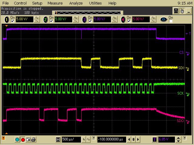
Note the following details of the code protection feature on Microchip devices:
•    Microchip products meet the specification contained in their particular Microchip Data Sheet.

•    Microchip believes that its family of products is one of the most secure families of its kind on the market today, when used in the
     intended manner and under normal conditions.

•    There are dishonest and possibly illegal methods used to breach the code protection feature. All of these methods, to our
     knowledge, require using the Microchip products in a manner outside the operating specifications contained in Microchip’s Data
     Sheets. Most likely, the person doing so is engaged in theft of intellectual property.

•    Microchip is willing to work with the customer who is concerned about the integrity of their code.

•    Neither Microchip nor any other semiconductor manufacturer can guarantee the security of their code. Code protection does not
     mean that we are guaranteeing the product as “unbreakable.”

Code protection is constantly evolving. We at Microchip are committed to continuously improving the code protection features of our
products. Attempts to break Microchip’s code protection feature may be a violation of the Digital Millennium Copyright Act. If such acts
allow unauthorized access to your software or other copyrighted work, you may have a right to sue for relief under that Act.

Information contained in this publication regarding device               Trademarks
applications and the like is provided only for your convenience          The Microchip name and logo, the Microchip logo, Accuron,
and may be superseded by updates. It is your responsibility to
                                                                         dsPIC, KEELOQ, KEELOQ logo, MPLAB, PIC, PICmicro,
ensure that your application meets with your specifications.
                                                                         PICSTART, rfPIC and SmartShunt are registered trademarks
MICROCHIP MAKES NO REPRESENTATIONS OR                                    of Microchip Technology Incorporated in the U.S.A. and other
WARRANTIES OF ANY KIND WHETHER EXPRESS OR
                                                                         countries.
IMPLIED, WRITTEN OR ORAL, STATUTORY OR
OTHERWISE, RELATED TO THE INFORMATION,                                   FilterLab, Linear Active Thermistor, MXDEV, MXLAB,
INCLUDING BUT NOT LIMITED TO ITS CONDITION,                              SEEVAL, SmartSensor and The Embedded Control Solutions
QUALITY, PERFORMANCE, MERCHANTABILITY OR                                 Company are registered trademarks of Microchip Technology
FITNESS FOR PURPOSE. Microchip disclaims all liability                   Incorporated in the U.S.A.
arising from this information and its use. Use of Microchip              Analog-for-the-Digital Age, Application Maestro, CodeGuard,
devices in life support and/or safety applications is entirely at        dsPICDEM, dsPICDEM.net, dsPICworks, dsSPEAK, ECAN,
the buyer’s risk, and the buyer agrees to defend, indemnify and          ECONOMONITOR, FanSense, In-Circuit Serial
hold harmless Microchip from any and all damages, claims,                Programming, ICSP, ICEPIC, Mindi, MiWi, MPASM, MPLAB
suits, or expenses resulting from such use. No licenses are              Certified logo, MPLIB, MPLINK, mTouch, PICkit, PICDEM,
conveyed, implicitly or otherwise, under any Microchip                   PICDEM.net, PICtail, PIC32 logo, PowerCal, PowerInfo,
intellectual property rights.                                            PowerMate, PowerTool, REAL ICE, rfLAB, Select Mode, Total
                                                                         Endurance, UNI/O, WiperLock and ZENA are trademarks of
                                                                         Microchip Technology Incorporated in the U.S.A. and other
                                                                         countries.
                                                                         SQTP is a service mark of Microchip Technology Incorporated
                                                                         in the U.S.A.
                                                                         All other trademarks mentioned herein are property of their
                                                                         respective companies.
                                                                         © 2008, Microchip Technology Incorporated, Printed in the
                                                                         U.S.A., All Rights Reserved.
                                                                              Printed on recycled paper.

                                                                         Microchip received ISO/TS-16949:2002 certification for its worldwide
                                                                         headquarters, design and wafer fabrication facilities in Chandler and
                                                                         Tempe, Arizona; Gresham, Oregon and design centers in California
                                                                         and India. The Company’s quality system processes and procedures
                                                                         are for its PIC® MCUs and dsPIC® DSCs, KEELOQ® code hopping
                                                                         devices, Serial EEPROMs, microperipherals, nonvolatile memory and
                                                                         analog products. In addition, Microchip’s quality system for the design
                                                                         and manufacture of development systems is ISO 9001:2000 certified.

DS51759A-page ii                                                                                        © 2008 Microchip Technology Inc.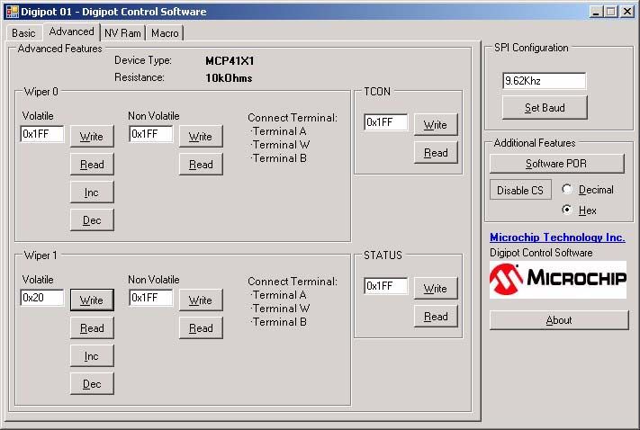
MCP42XX PICTAIL™ PLUS
                                               DAUGHTER BOARD USER’S GUIDE

                                                 Table of Contents
Preface ........................................................................................................................... 1
                    Introduction............................................................................................................ 1
                    Document Layout .................................................................................................. 1
                    Conventions Used in this Guide ............................................................................ 2
                    Recommended Reading........................................................................................ 3
                    The Microchip Web Site ........................................................................................ 3
                    Customer Support ................................................................................................. 3
                    Document Revision History ................................................................................... 3
Chapter 1. Product Overview
                    1.1 Introduction ..................................................................................................... 5
                    1.2 What is the MCP42XX PICtail Plus Daughter Board? .................................... 6
                    1.3 What the MCP42XX PICtail Plus Daughter Board Kit includes ...................... 7
Chapter 2. Installation and Operation
                    2.1 Introduction ..................................................................................................... 9
                    2.2 Features ......................................................................................................... 9
                    2.3 Getting Started ............................................................................................. 10
                    2.4 Explorer 16 Daughter Demo Board Demos .................................................. 14
Appendix A. Schematic and Layouts
                    A.1 Introduction .................................................................................................. 29
                    A.2 Schematics and PCB Layout ....................................................................... 29
                    A.3 Board - Schematic ....................................................................................... 30
                    A.4 Board – Top Silk-screen Layer .................................................................... 31
                    A.5 Board – Top Components + Silk-Screen ..................................................... 32
                    A.6 Board – Ground Layer ................................................................................. 33
                    A.7 Board – Power Layer ................................................................................... 34
                    A.8 Board – Bottom Layer .................................................................................. 35
Appendix B. Bill Of Materials (BOM)
Appendix C. Board Testing
                    C.1 Introduction .................................................................................................. 39
                    C.2 What is Tested ............................................................................................. 40
                    C.3 What is NOT Tested .................................................................................... 40
Worldwide Sales and Service .................................................................................... 42

© 2008 Microchip Technology Inc.                                                                                         DS51759A-page iii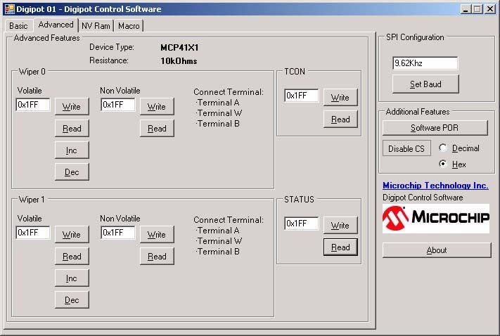
MCP42XX PICtail™ Plus Daughter Board User’s Guide
NOTES:

DS51759A-page iv                    © 2008 Microchip Technology Inc.
MCP42XX PICTAIL™ PLUS
                                        DAUGHTER BOARD USER’S GUIDE

                                                 Preface

                                     NOTICE TO CUSTOMERS
   All documentation becomes dated, and this manual is no exception. Microchip tools and
   documentation are constantly evolving to meet customer needs, so some actual dialogs
   and/or tool descriptions may differ from those in this document. Please refer to our web site
   (www.microchip.com) to obtain the latest documentation available.
   Documents are identified with a “DS” number. This number is located on the bottom of each
   page, in front of the page number. The numbering convention for the DS number is
   “DSXXXXXA”, where “XXXXX” is the document number and “A” is the revision level of the
   document.
   For the most up-to-date information on development tools, see the MPLAB® IDE on-line help.
   Select the Help menu, and then Topics to open a list of available on-line help files.

INTRODUCTION
                       This chapter contains general information that will be useful to know before using the
                       MCP42XX PICtail Plus Daughter Board User’s Guide. Items discussed in this chapter
                       include:
                       •   Document Layout
                       •   Conventions Used in this Guide
                       •   Recommended Reading
                       •   The Microchip Web Site
                       •   Customer Support
                       •   Document Revision History

DOCUMENT LAYOUT
                       This document describes how to use the MCP42XX PICtail Plus Daughter Board
                       User’s Guide as a development tool to emulate and debug firmware on a target board.
                       The manual layout is as follows:
                       • Chapter 1. “Product Overview” – Important information about the MCP42XX
                         PICtail Plus Daughter Board User’s Guide.
                       • Chapter 2. “Installation and Operation” – Includes instructions on how to get
                         started with this user’s guide and a description of the user’s guide.
                       • Appendix A. “Schematic and Layouts” – Shows the schematic and layout
                         diagrams for the MCP42XX PICtail Plus Daughter Board User’s Guide.
                       • Appendix B. “Bill Of Materials (BOM)” – Lists the parts used to build the
                         MCP42XX PICtail Plus Daughter Board User’s Guide.
                       • Appendix C. “Board Testing” – Describes the testing method for the MCP42XX
                         PICtail Plus Daughter Board User’s Guide and what aspects of the board are and
                         are not tested.

© 2008 Microchip Technology Inc.                                                              DS51759A-page 1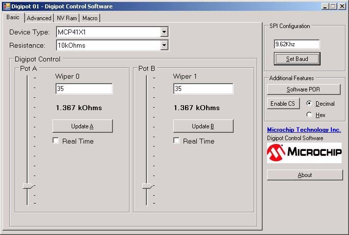
MCP42XX PICtail™ Plus Daughter Board User’s Guide

CONVENTIONS USED IN THIS GUIDE
                  This manual uses the following documentation conventions:

                  DOCUMENTATION CONVENTIONS
                            Description                   Represents                          Examples
                  Arial font:
                  Italic characters              Referenced books                    MPLAB® IDE User’s Guide
                                                 Emphasized text                     ...is the only compiler...
                  Initial caps                   A window                            the Output window
                                                 A dialog                            the Settings dialog
                                                 A menu selection                    select Enable Programmer
                  Quotes                         A field name in a window or         “Save project before build”
                                                 dialog
                  Underlined, italic text with   A menu path                         File>Save
                  right angle bracket
                  Bold characters                A dialog button                     Click OK
                                                 A tab                               Click the Power tab
                  N‘Rnnnn                        A number in verilog format,         4‘b0010, 2‘hF1
                                                 where N is the total number of
                                                 digits, R is the radix and n is a
                                                 digit.
                  Text in angle brackets < >     A key on the keyboard               Press ,
                  Courier New font:
                  Plain Courier New              Sample source code                  #define START
                                                 Filenames                           autoexec.bat
                                                 File paths                          c:\mcc18\h
                                                 Keywords                            _asm, _endasm, static
                                                 Command-line options                -Opa+, -Opa-
                                                 Bit values                          0, 1
                                                 Constants                           0xFF, ‘A’
                  Italic Courier New             A variable argument                 file.o, where file can be
                                                                                     any valid filename
                  Square brackets [ ]            Optional arguments                  mcc18 [options] file
                                                                                     [options]
                  Curly brackets and pipe        Choice of mutually exclusive        errorlevel {0|1}
                  character: { | }               arguments; an OR selection
                  Ellipses...                    Replaces repeated text              var_name [,
                                                                                     var_name...]
                                                 Represents code supplied by         void main (void)
                                                 user                                { ...
                                                                                     }

DS51759A-page 2                                                                      © 2008 Microchip Technology Inc.
Preface

RECOMMENDED READING
                       This user's guide describes how to use MCP42XX PICtail Plus Daughter Board User’s
                       Guide. Other useful documents are listed below. The following Microchip documents
                       are available and recommended as supplemental reference resources.
                       AN1080 Application Note, “Understanding Digital Potentiometer Resistor Varia-
                       tions”, DS01080
                       These data sheets provides detailed information regarding the MCP41XX/42XX
                       product family:
                       MCP413x/415x/423x/425x Data Sheet, “7/8-Bit Single/Dual SPI Digital POT with
                       Non-Volatile Memory“, DS22059
                       MCP414x/416x/424x/426x Data Sheet, “7/8-Bit Single/Dual SPI Digital POT with
                       Volatile Memory“, DS22060

THE MICROCHIP WEB SITE
                       Microchip provides online support via our web site at www.microchip.com. This web
                       site is used as a means to make files and information easily available to customers.
                       Accessible by using your favorite Internet browser, the web site contains the following
                       information:
                       • Product Support – Data sheets and errata, application notes and sample
                         programs, design resources, user’s guides and hardware support documents,
                         latest software releases and archived software
                       • General Technical Support – Frequently Asked Questions (FAQs), technical
                         support requests, online discussion groups, Microchip consultant program
                         member listing
                       • Business of Microchip – Product selector and ordering guides, latest Microchip
                         press releases, listing of seminars and events, listings of Microchip sales offices,
                         distributors and factory representatives

CUSTOMER SUPPORT
                       Users of Microchip products can receive assistance through several channels:
                       •   Distributor or Representative
                       •   Local Sales Office
                       •   Field Application Engineer (FAE)
                       •   Technical Support
                       Customers should contact their distributor, representative or field application engineer
                       (FAE) for support. Local sales offices are also available to help customers. A listing of
                       sales offices and locations is included in the back of this document.
                       Technical support is available through the web site at: http://support.microchip.com

DOCUMENT REVISION HISTORY
                       Revision A (September 2008)
                       • Initial Release of this Document.

© 2008 Microchip Technology Inc.                                                                 DS51759A-page 3
MCP42XX PICtail™ Plus Daughter Board User’s Guide
NOTES:

DS51759A-page 4                     © 2008 Microchip Technology Inc.

MCP42XX PICTAIL™ PLUS
                                       DAUGHTER BOARD USER’S GUIDE

                               Chapter 1. Product Overview
1.1      INTRODUCTION
                       The MCP42XX PICtail Plus Daughter Board demonstrates the features and abilities of
                       Microchip’s MCP41XX and MCP42XX Digital Potentiometers. This board is designed
                       to exclusively use the MCP42XX devices.
                       The MCP41XX and MCP42XX are Digital Potentiometers with an SPI interface. These
                       devices have either 7-bits or 8-bits of resolution, single or dual offering, and are
                       available as either volatile or non-volatile memory options.
                       This board is designed to easily operate with any of the following:
                       • PIC24 Explorer 16 Demo Board (DM240001)
                       • PICkit™ Serial Analyzer (DV164122)
                       • Other PICDEM Demo Board that includes a PICtail Plus female connector
                       The use of the PIC24 Explorer 16 Demo Board (DM240001) will require a tool to
                       program the supplied firmware into the PIC24FJ128GA010 device. The use of any
                       other PICDEM Demo Board will require the user to modify the supplied “C” source
                       program appropriately.
                       The use of the PICkit Serial Analyzer will require the PC GUI interface program to
                       control the command and data sent to the MCP42XX devices serial port. The PICkit
                       Serial Analyzer GUI may be used, or the provided dedicated GUI may be used. The
                       source code for this dedicated GUI is available, but not supported (as is).
                       This chapter covers the following topics:
                       • What is the MCP42XX PICtail Plus Daughter Board?
                       • What the MCP42XX PICtail Plus Daughter Board Kit includes

© 2008 Microchip Technology Inc.                                                             DS51759A-page 5
MCP42XX PICtail™ Plus Daughter Board User’s Guide
1.2 WHAT IS THE MCP42XX PICTAIL PLUS DAUGHTER BOARD?
The MCP42XX PICtail Plus Daughter Board is used to demonstrate the use of Digital
Potentiometers. This board is designed to be used in conjunction with either the PIC24
Explorer 16 Demo Board or the PICkit™ Serial Analyzer. Figure 1-1 shows the boards
component placement and the purpose of the jumpers.
The board has an MCP4261-103 (10 kΩ) device for evaluation. This device is in the
TSSOP package (U2). This is a dual 8-bit Non-Volatile Potentiometer device. The
MCP4261 uses an SPI interface and can be controlled via the PICkit Serial Analyzer
interface (J1) or via the PICtail Plus interface (J3).
When using the PICtail Plus interface, the CS voltages can be taken to a VIHH level for
high voltage commands. This is done by controlling the selection of the analog switch
device (U1).
Jumpers allow the Terminal A and Terminal B voltages to be tied to AVDD and VSS, or
come from and external source.
Selects source
of Terminal A0
Voltage. Either
AVDD or VA0
Selects source
of Terminal B0
Not Installed
Voltage. Either
AVSS or VB0
Selects source
of Terminal A1
Voltage. Either
AVDD or VA1
PICkit Serial Selects source
Analyzer of Terminal B1
Interface (SPI) Voltage. Either
AVSS or VB1
Connects Connects
Wipers Explorer 16
(W0 and W1) +5V signal to
to PIC24 Analog AVDD signal
Inputs
FIGURE 1-1: MCP42XX Explorer 16 Daughter Board Demo Board Connectors.
DS51759A-page 6 © 2008 Microchip Technology Inc.Product Overview
Some of the features of the board include:
• PICkit Serial Analyzer Interface (J1)
• PICtail Plus Interface (J3)
• MAX4582L High Voltage analog switch to allow CS voltage to be selected as one
of four voltages (VSS, 3.3V, 5.0V, or 9.0V) - High Voltage command support
• Jumpers (JP2:JP3) to connect Wiper pins (W0 and W1) to PICDEM Analog
Channels
• Jumper (JP1) to allow AVDD to be driven by external power supply while
connected to PICDEM board or PICkit Serial Analyzer
• Jumpers to allow Terminal A pins to be connected to AVDD or VAx pad
• Jumpers to allow Terminal B pins to be connected to VSS or VBx pad
• Connection point for easy connection to Resistor Network Terminal pins
1.3 WHAT THE MCP42XX PICTAIL PLUS DAUGHTER BOARD KIT INCLUDES
This MCP42XX PICtail Plus Daughter Board Kit includes:
• One MCP42XX PICtail Plus Daughter Board, 102-00182
• Analog and Interface Products Demonstration Boards CD-ROM (DS21912)
- MCP42XX PICtail™ Plus Daughter Board User’s Guide, (DS51759)
- PICkit Serial Analyzer PC GUI (executable and source code) - supplied “As
Is”
© 2008 Microchip Technology Inc. DS51759A-page 7MCP42XX PICtail™ Plus Daughter Board User’s Guide NOTES: DS51759A-page 8 © 2008 Microchip Technology Inc.
MCP42XX PICTAIL™ PLUS
                                       DAUGHTER BOARD USER’S GUIDE

                      Chapter 2. Installation and Operation
2.1      INTRODUCTION
                       The MCP42XX PICtail Plus Daughter Board is used to demonstrate the operation of
                       Digital Potentiometer. The operation of the MCP41XX devices is similar to the
                       MCP42XX devices. Therefore, this demo board can be used as a development plat-
                       form for either device family.
                       This board is designed to be used in conjunction with either the PIC24 Explorer 16
                       Demo Board or the PICkit™ Serial Analyzer.

2.2      FEATURES
                       This board supports the following features
                       • Each digital potentiometers Terminal A pin can be individually connected to either
                         AVDD or the corresponding VAx pad
                       • Each digital potentiometers Terminal B pin can be individually connected to either
                         AVSS or the corresponding VBx pad
                       • Can control the voltage on the MCP4261’s CS pin to either VSS, 3.3V, 5.0V, or
                         9.0V via control signals from the PICtail Plus interface (J3)
                       • Can Control the MCP4261 via the PICkit™ Serial Analyzer interface (J1)
                       • PIC24 can monitor the voltage levels of the MCP4261’s W0 and W1 pins
                       • Supplied with a “C” program that demonstrates normal and high voltage
                         commands
                       • Demonstrates a split rail application, with digital logic at 3.3V and analog
                         operation at 5.0V

© 2008 Microchip Technology Inc.                                                              DS51759A-page 9
MCP42XX PICtail™ Plus Daughter Board User’s Guide
2.3 GETTING STARTED
Figure 2-1 shows a simplified circuit for the MCP42XX PICtail Plus Daughter Board.
The layout of the board is shown in Figure 2-3. This board can be operated with either
a PICDEM board with a PICtail Plus header or the PICkit Serial Analyzer. The
MCP42XX PICtail Plus Daughter Board kit comes with firmware for the Explorer 16
Starter Kit (DV164033). The layout of this board is shown in Figure 2-5.
The MCP42XX PICtail Plus Daughter Board supports the following Microchip Digital
Potentiometer devices; which allows demonstration of all MCP42XX devices
• MCP42X1
J1
AVDD VSS VA0
AVDD
PICVDD R1 AVDD MCP4261
(+5.0V) (TSSOP) JP1
C1 C2 VSS
VSS
RAB0
VW0
R2 R3 R4 R5 R6 R7 JP2
CS0
RB2 (CS0)
SDI VSS
SDI VB0
SDO VA1
SDO AVDD
SCK SCK
WP JP3
RF0 (WP)
SHDN
RAB1
RF1 (SHDN) VW1
SDA2
JP4
SCL2
J2 VSS
VW0 1 2 VB1
RB0/AN0 RB2 RF2
VW1 MAX4582L
RB1/AN1 SCK1 RF3
J3 CS0 Y VDD +9.0V
PIC SDI1 SCL1 RD14
Explorer 16 RB2 A Y0 +5.0V
SDO1 SDA1 RD15
Interface B
VSS VSS Y1 +3.3V
C Y2 VSS
CS AN0 AN1 VSS VSS VSS
VDD VSS EN Y3 +9.0V
RB3/AN3 RB4/AN4
VSS VSS VSS
SDI2 (To SDO) RE9 RE8 Pin # SPI Name I2C Name
SCK2 (To SCK) 1 CS HVC/A0
RD14 RD15 2 SCK
SDO2 (To SDI) SCL
+3.3V +3.3V 3 SDI SDA
H1 (PICkit Serial Interface) +5.0V +5.0V 4 VSS VSS
5 P1B PICkit Serial 6-Pin Interface
+9.0V P1B
+9.0V 6 P1W Pin # SPI Name I2C Name
NC P1W
RG0 RF0 7 P1A P1A 6 SDO —
VDD 5 SCK
RG1 RF1 8 P0A P0A SCL
VSS Connector 9 P0W P0W 4 SDI SDA
SDA RG9 RF4 10 P0B 3 VSS VSS
Orientation P0B
Notch SCK2 RF5 11 WP WP 2 VDD VDD
SCL
SDI2 12 SHDN A2 1 CS —
NC SCL2
13 SDO A1
SDO2 SDA2 14 VDD VDD
H2 (PICkit Serial Interface)
FIGURE 2-1: MCP41XX Simplified Circuit.
DS51759A-page 10 © 2008 Microchip Technology Inc.Installation and Operation
2.3.1 The Hardware
Figure 2-2 shows the component placement of the MCP42XX PICtail Plus Daughter
Board as well as the operation of the board jumpers.
The VAx and VBx pads allow an external voltage source to be applied to the device’s
desired Terminal A or Terminal B pin. The VWx pad is directly connected to the corre-
sponding Terminal W pin, which makes it easy to measure the resulting voltage. The
AVDD pad allows an external power supply to power the board, which should improve
performance compared to powering the board via the PICtail Plus header or the PICkit
Serial Analyzer.
The Printed Circuit Board (PCB) has been designed for the support of the SPI and I2C
device families (MCP42XX and MCP46XX), so not all components are installed for the
SPI version of the demo board.
2.3.1.1 JUMPER DESCRIPTIONS
Figure 2-2 shows the function of the demo board jumpers. Some of the jumpers con-
figure the voltage source of the Terminal A and Terminal B pins while others determine
the connection of the W pins. Lastly there is a jumper to ensure that drive conflicts do
not occur if an external power supply is being used for the AVDD voltage.
The default jumper configuration for the shipped demo board is shown in Figure 2-3.
© 2008 Microchip Technology Inc. DS51759A-page 11MCP42XX PICtail™ Plus Daughter Board User’s Guide
JMP1:JMP3 -
Terminal A Source
VAx Pad
AVDD JMP2:JMP4 -
Terminal B Source
VBx Pad
JP3 - PIC24 AN1 pin VSS
AN1 connected to W1
AN1 not connected
JP2 - PIC24 AN0 pin JP1 - Explorer 16 5V signal to AVDD plane
AN0 connected to W0 Explorer 16 5V signal connected to
MCP42XXDM-PTPLS AVDD plane
AN0 not connected Explorer 16 5V signal not connected to
MCP42XXDM-PTPLS AVDD plane
FIGURE 2-2: MCP42XXDM-PTPLS Jumper Configuration and Oscilloscope Test Points.
DS51759A-page 12 © 2008 Microchip Technology Inc.Installation and Operation
FIGURE 2-3: MCP42XX PICtail Plus Daughter Board Layout with Default Jumper Settings
Note: This is the Jumper configuration that the board should be shipped with.
© 2008 Microchip Technology Inc. DS51759A-page 13MCP42XX PICtail™ Plus Daughter Board User’s Guide
2.4 EXPLORER 16 DAUGHTER DEMO BOARD DEMOS
This section describes how to demonstrate the MCP42XX PICtail Plus Daughter
Board. The demos will either use an Explorer 16 Developers Board or a PICkit Serial
Analyzer.
The demo using the Explorer 16 Developers Board is discussed in
Section 2.4.1 “Demos with the Explorer 16 Starter Kit”. While the demo using the
PICkit Serial Analyzer is discussed in Section 2.4.2 “Demo with the PICkit Serial
Analyzer”.
Note: Both demos require that the MCP42XXDM-PTPLS board jumper settings
are as shown in Figure 2-4.
2.4.1 Demos with the Explorer 16 Starter Kit
Note: For information on how to use the MPLAB-IDE, ICD-2, or any other aspect
of the PIC Development tool platform, please refer to the appropriate
documentation.
This Demo will use the Explorer 16 Starter Kit. This board needs to be programmed
with the supplied firmware. This firmware can be found on the included CD-ROM or can
be downloaded from the Microchip web site. It is good practice to check the Microchip
web site for updates to the demo firmware.
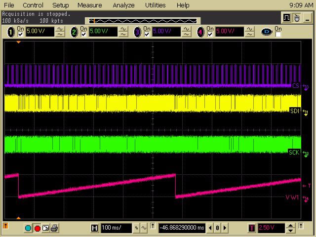
The supplied firmware program has two modes of operation. In the first mode, the
program generates a saw wave on the VW1 pin (see Figure 2-6). The second mode is
to display the operation of High Voltage commands to Wiper 1 (see Figure 2-7). This is
where the CS signal is driven to 9V.
The program selected is determined after a reset (including the Power-on reset) by the
state of the S3 switch. The programs are:
• Wiper 1 Saw Wave (Switch S3 not depressed)
• Increment / Decrement with High Voltage Write to Non-Volatile Wiper 1 Register
(Switch S3 depressed)
Table 2-1 shows the required hardware to operate the demo.
TABLE 2-1: DEMO HARDWARE REQUIREMENTS
Item # Description Comment
1 Explorer 16 Developers Board and power supply Note 1
(DV164033)
2 MCP42XXDM-PTPLS
3 4 Channel oscilloscope Note 2
Note 1: A development tool to program the Explorer 16 Developers Board is required. This
development tool could be Microchip’s MPLAB ICD-2.
2: An oscilloscope with fewer channels can be used, but this will require that the
probes be moved between signals to verify the output states. A 2 channel is the
minimum requirement, but is not recommended.
DS51759A-page 14 © 2008 Microchip Technology Inc.Installation and Operation
2.4.1.1 THE MCP42XXDM-PTPS JUMPER CONFIGURATION
Before inserting the board into the Explorer 16 Developers Board, the jumper
configuration must be verified. Figure 2-4 shows the configurations of the jumpers.
Channel 1
Channel 4
(Program 2 SDO Signal)
Channel 4
Channel 3
Channel 2
FIGURE 2-4: MCP4XXDM-PTPLS Jumper Configuration and Oscilloscope Test Points.
Note: This is the Jumper configuration that the board should be shipped with.
© 2008 Microchip Technology Inc. DS51759A-page 15MCP42XX PICtail™ Plus Daughter Board User’s Guide
2.4.1.2 MCP42XX PICTAIL PLUS DAUGHTER BOARD (MCP42XXDM-PTPLS)
INTO THE EXPLORER 16 STARTER KIT (DV164033)
Figure 2-5 shows the component placement on the Explorer 16 Demo Board including
the PICtail Plus header that the MCP42XX PICtail Plus Daughter Board is inserted into.
The boards Reset switch and other switches are pointed out.
Ensure that the MCP42XXDM-PTPLS is installed in the correct orientation into the
Explorer 16 Developers Board. Figure 2-5 shows the location where the daughter
board is inserted into the Explorer 16 Developers Board.
Explorer 16
Development
Board reset
switch
Connector
(female) for
MCP42XXDM-
PTPLS board
M
S3 (RD6) S6 (RD7) S4 (RD13)
Switch State Increment Volatile Wiper1 Decrement Volatile Wiper1
selects program S5 (RA7)
at POR or after Read Volatile Wiper1, then
MCLR reset Write Non-Volatile Wiper1
FIGURE 2-5: Explorer 16 Development Board (DV164033).
DS51759A-page 16 © 2008 Microchip Technology Inc.Installation and Operation
2.4.1.3 DEMO STEPS
The PIC24 Board firmware contains two programs. The program selected is deter-
mined after a reset (including the Power-on reset) by the state of the S3 switch. The
programs are:
1. Wiper 1 Saw Wave (Switch S3 not depressed).
2. Increment / Decrement with High Voltage Write to Non-Volatile Wiper 1 Register
(Switch S3 depressed).
Table 2-2 shows the sequence of steps to demo the MCP42XXDM-PTPLS board with
the Explorer 16 Developer’s Board.
Figure 2-6 shows the expected output waveform for Program #1 (Wiper 1 Saw Wave)
as well as the voltage levels and ranges of the four signals. Figure 2-7 shows an exam-
ple waveforms for the High Voltage Write Command for the SDI, SDO, SCK, and CS
signals.
TABLE 2-2: DEMO STEPS USING THE PICDEM HPC EXPLORER DEMO
BOARD
Step Action Result
1a Turn on oscilloscope and configure as follows: —
• Channel 1, 2, 3, and 4 @ 5V/Division
• Channel 1 to 4 have same ground
reference point
1b Configure oscilloscope as follows: —
• Time-base = 100 ms/Division
(see Figure 2-6 for scope details)
2 Configure the MCP42XXDM-PTPLS to the —
jumper settings shown in Figure 2-4.
3 Insert the MCP42XXDM-PTPLS board into the —
Explorer 16 Developers Board J5 header (see
Figure 2-5). Ensure proper orientation of
Daughter Board to J5 Header.
4 Connect the oscilloscope probes as follows: —
• Channel 1 to the CS Pin of Header J1
• Channel 2 to the SDI Pin of Header J1
• Channel 3 to the SCK Pin of Header J1
• Channel 4 to the VW1 Pad
5 Power up the programmed Explorer 16 Devel- Program 1 is now selected.
oper Board and depress and release the MCLR Output waveform should look similar
push button to Figure 2-6. Ensure to verify volt-
age levels/ranges of the four signals.
(Note 1)
6 Depress the Explorer 16 Developer Board’s S3 —
push button
7 Depress and release the Explorer 16 Developer —
Board’s MCLR push button
8 Release the Explorer 16 Developer Board’s S3 Program 2 is now selected.
push button
9 Configure oscilloscope as follows: —
• Time-base = 50 µs/Division
(see Figure 2-7 for scope details)
Note 1: The SDI and SCK signals go from VSS to approximately 3.3V due to the PIC24
operating at 3.3V. The VW1 signals go from VSS to approximately 5V.
© 2008 Microchip Technology Inc. DS51759A-page 17MCP42XX PICtail™ Plus Daughter Board User’s Guide
TABLE 2-2: DEMO STEPS USING THE PICDEM HPC EXPLORER DEMO
BOARD (CONTINUED)
Step Action Result
10 Depress the Explorer 16 Developer Board’s S6 While S6 is depressed, the voltage
push button on Wiper 1 (VW1) increases
11 Depress the Explorer 16 Developer Board’s S4 While S4 is depressed, the voltage
push button on Wiper 1 (VW1) decreases
12 Use the S4 and S6 push buttons to configure —
the volatile wiper 1 register to either near VDD
or near VSS. Take note of Wiper Voltage value.
13 Move Channel 4 scope probe (VW1) to SDO —
signal on J1 (see Figure 2-4)
14 Configure Scope to Capture on Channel 1 (CS —
pin) on the rising edge at about 7V.
15 Depress the Explorer 16 Developer Board’s S5 While S5 is depressed, the volatile
push button Wiper 1 register is read, this value is
written to the Non-Volatile Wiper 1
register, and then approximately a
10ms delay occurs while the NV write
cycle occurs. Capture will look similar
to Figure 2-7 (Note 1)
16 Unplug Power from the Explorer 16 Developer —
Board
17 Depress the Explorer 16 Developer Board’s S3 —
push button
18 Power up the programmed Explorer 16 Devel- —
oper Board and depress and release the MCLR
push button
19 Release the Explorer 16 Developer Board’s S3 The voltage on the Wiper 1 pad
push button (VW1) should be the same voltage
level as when completed with Step
12.
20 Unplug Power from the Explorer 16 Developer —
Board and remove the MCP42XXDM-PTPLS
board
Note 1: The SDI and SCK signals go from VSS to approximately 3.3V due to the PIC24
operating at 3.3V. The VW1 signals go from VSS to approximately 5V.
DS51759A-page 18 © 2008 Microchip Technology Inc.Installation and Operation
FIGURE 2-6: Screen Capture of Program 1 Output Waveforms.
FIGURE 2-7: Screen Capture of Program 2 Non-Volatile Write Waveform.
© 2008 Microchip Technology Inc. DS51759A-page 19MCP42XX PICtail™ Plus Daughter Board User’s Guide
2.4.2 Demo with the PICkit Serial Analyzer
Note: For information on how to use the PICkit Serial Analyzer, or any other
aspect of the PIC® Development tool platform, please refer to the
appropriate documentation.
This demo requires that you have previously installed the PICkit Serial Analyzer
(DV164122) on your computer. Ensure that the device has properly been installed
before using the Supplied GUI for the MCP41XX/42XX devices.
Note 1: The GUI is supplied “As Is”, and the source code is supplied to allow
developers a starting point for any GUI development.
2: The GUI will be updated to include the selection of I2C devices
(MCP45XX/46XX).
The GUI requires two files, these are:
• DigipotControl.exe
• PICkitS.dll
The “PICkitS.dll” file must be in the same directory as the application executable file.
Table 2-3 shows the required hardware to operate the demo.
TABLE 2-3: DEMO HARDWARE REQUIREMENTS
Item # Description Comment
1 PC with USB port running Windows XP
2 PICkit Serial Analyzer Adapter (DV164122)
3 MCP42XXDM-PTPLS
4 Oscilloscope Note 1
Note 1: A Digital Multi-Meter (DMM) may be used to measure the W pins voltage.
DS51759A-page 20 © 2008 Microchip Technology Inc.Installation and Operation
2.4.2.1 THE GUI SCREENS AND GUI CONFIGURATION
Figure 2-8 shows the GUI when the application is first started.
FIGURE 2-8: 1st Screen of GUI.
Figure 2-9 shows the GUI box where the SPI Baud Rate is specified. Clicking on the
“Set Baud” button results in an actual Baud Rate of 9.62 kHz, as shown in Figure 2-10.
This reflects the actual Baud Rate based on the PICkit Serial Analyzer’s clock fre-
quency.
FIGURE 2-9: Configuring the Baud Rate - Desired Baud Rate.
© 2008 Microchip Technology Inc. DS51759A-page 21MCP42XX PICtail™ Plus Daughter Board User’s Guide
FIGURE 2-10: Configuring the Baud Rate - Actual Baud Rate.
To display the data values in hexidecimal, click on the Hex radial button. To Chip Select
the MCP42XX device, click on the “Disable CS” button. The GUI window will now look
like Figure 2-11. To have access to more control of the MCP42XX memory, click on the
Advanced tab, and the GUI will display Figure 2-12.
FIGURE 2-11: Enabling The MCP42XX Chip Select.
DS51759A-page 22 © 2008 Microchip Technology Inc.Installation and Operation
FIGURE 2-12: Advance Screen.
Clicking on the Read Button should display the register values shown in Figure 2-13.
The volatile wiper value should match the Non-volatile wiper value.
Note: The Volatile/Non-Volatile wiper values may not be the device’s expected
Mid-scale value due to board production testing.
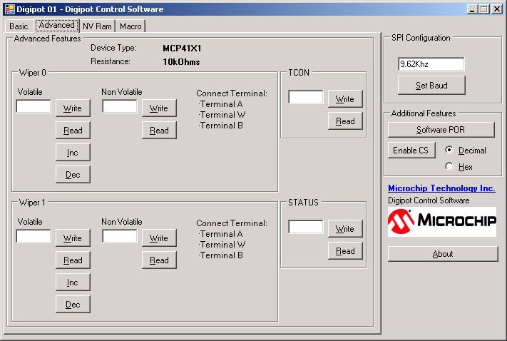
To write to a desired register, in the desired data entry box and click on the Write button.
Figure 2-14 shows an example of writing to the Volatile Wiper 0 register.
FIGURE 2-13: Advance Screen - Read Register.
© 2008 Microchip Technology Inc. DS51759A-page 23MCP42XX PICtail™ Plus Daughter Board User’s Guide
FIGURE 2-14: Advance Screen - Write Register.
DS51759A-page 24 © 2008 Microchip Technology Inc.Installation and Operation
Figure 2-15 shows the connections for the Demo using the PICkit Serial Analyzer.
Insert PICkit Serial
Analyzer into
this Header
Channel 1
FIGURE 2-15: PICkit Serial Analyzer Demo Jumper Configuration and Oscilloscope Test Points.
© 2008 Microchip Technology Inc. DS51759A-page 25MCP42XX PICtail™ Plus Daughter Board User’s Guide
2.4.2.2 DEMO STEPS
The use of the PICkit Serial Analyzer means that wiper pin’s voltage is under direct
control from the PC’s GUI interface and more user experimentation is possible.
TABLE 2-4: DEMO STEPS USING THE PICDEM HPC EXPLORER DEMO
BOARD
Step Action Result
1a Turn on oscilloscope and configure as follows: —
• Channel 1 @ 1V/Division (Note 1)
1b Configure oscilloscope as follows: —
• Time-base = 100 µs/Division (Note 1)
2 Configure the MCP42XXDM-PTPLS to the —
jumper settings shown in Figure 2-15.
3 Insert the PICkit Serial Analyzer into the —
MCP42XXDM-PTPLS board’s J1 header.
Ensure proper orientation of the PICkit Serial
Analyzer to the J1 Header.
4 Connect the oscilloscope probes as follows: —
• Channel 1 to the VW1 Pad
5 Plug the PICkit Serial into the PC’s USB port —
6 Plug the PICkit Serial into the The MCP42XXDM-PTPLS board is
MCP42XXDM-PTPLS board’s J1 connector now powered
7 Start the GUI application See Figure 2-8 and
8 Select a Baud rate of 9600 See Figure 2-9 and Figure 2-10
9 Under Additional Features, select the “Hex” See Figure 2-11. The button’s text
radial button and then Click on the “Enable CS” changes to “Disable CS”
button. This drives the CS signal low. This
Enables the MCP42XX to receive serial com-
mands.
10 Click on the “Advanced” tab The Advanced screen appears, see
Figure 2-12
11 Click on all 6 “Read” buttons See Figure 2-13
12 In the Volatile Wiper 1 register text box, type a See Figure 2-14
value that is significantly different then the cur-
rent value. Such as, if the value was 1FFh, type
20h.
13 Click on the associated “Write” button The VW1 voltage (on the oscillo-
scope) changes.
14 Type other values and then click on the “Write” Look on the oscilloscope to monitor
button to see how the VW1 voltage changes the Wiper 1 voltage after each click of
the “Write” button.
15 In the Wiper 1 text box, type 080h (mid-scale) The VW1 pin should go to AVDD / 2
Note 1: A Digital Multi-Meter (DMM) configured to measure voltage may be used instead of
an oscill0scope.
DS51759A-page 26 © 2008 Microchip Technology Inc.Installation and Operation
TABLE 2-4: DEMO STEPS USING THE PICDEM HPC EXPLORER DEMO
BOARD (CONTINUED)
Step Action Result
16 Now write values to the TCON register (bit 7 to The different Potentiometer termi-
bit 4) and monitor the effects on the VW1 pin. nals (A1, W1, and B1), will be either
connected or disconnected depend-
ing on the value.
TCON = Result
‘x 1110 xxxx’b B1 open,
W1 pulled high
‘x 1011 xxxx’b A1 open,
W1 pulled low
‘x 1101 xxxx’b W1 floating
‘x 0111 xxxx’b A1 open,
W1 connected to
B1 (Zero-Scale)
‘x 1111 xxxx’b All terminals con-
nected to their
respective pin
17 Write assorted values to the devices memory
locations and then read the values to see what
is present. If the write is to Non-Volatile mem-
ory, power down (unplug) the MCP42XX PICtail
Plus Daughter Board and then power up to
evaluate if the non-volatile memory value is
retained.
Note 1: A Digital Multi-Meter (DMM) configured to measure voltage may be used instead of
an oscill0scope.
© 2008 Microchip Technology Inc. DS51759A-page 27MCP42XX PICtail™ Plus Daughter Board User’s Guide NOTES: DS51759A-page 28 © 2008 Microchip Technology Inc.
MCP42XX PICTAIL™ PLUS
                                        DAUGHTER BOARD USER’S GUIDE

                           Appendix A. Schematic and Layouts
A.1      INTRODUCTION
                       This appendix contains the schematics and layouts for the MCP42XX PICtail Plus
                       Daughter Board. Diagrams included in this appendix:
                       •   Board - Schematic
                       •   Board - Top Silk-screen Layer
                       •   Board - Top Component Plus Silk-screen
                       •   Board - Ground Layer
                       •   Board - Power Layer
                       •   Board - Bottom Layer

A.2      SCHEMATICS AND PCB LAYOUT
                       Figure A.3 shows the schematic of the MCP42XX PICtail Plus Daughter Board.
                       Figure A.4 shows the layout for the top layer of the MCP42XX PICtail Plus Daughter
                       Board. The layer order is shown in Figure A-1.

                       FIGURE A-1:          LAYER ORDER

                                                                       Top Layer
                                                                       Ground Layer
                                                                       Power Layer
                                                                       Bottom Layer

© 2008 Microchip Technology Inc.                                                          DS51759A-page 29
MCP42XX PICtail™ Plus Daughter Board User’s Guide
A.3 BOARD - SCHEMATIC
M
DS51759A-page 30 © 2008 Microchip Technology Inc.Schematic and Layouts A.4 BOARD – TOP SILK-SCREEN LAYER © 2008 Microchip Technology Inc. DS51759A-page 31
MCP42XX PICtail™ Plus Daughter Board User’s Guide

A.5     BOARD – TOP COMPONENTS + SILK-SCREEN

DS51759A-page 32                               © 2008 Microchip Technology Inc.
Schematic and Layouts

A.6      BOARD – GROUND LAYER

© 2008 Microchip Technology Inc.                DS51759A-page 33
MCP42XX PICtail™ Plus Daughter Board User’s Guide

A.7     BOARD – POWER LAYER

DS51759A-page 34                    © 2008 Microchip Technology Inc.
Schematic and Layouts

A.8      BOARD – BOTTOM LAYER

© 2008 Microchip Technology Inc.                DS51759A-page 35
MCP42XX PICtail™ Plus Daughter Board User’s Guide
NOTES:

DS51759A-page 36                    © 2008 Microchip Technology Inc.
MCP42XX PICTAIL™ PLUS
                                            DAUGHTER BOARD USER’S GUIDE

                           Appendix B. Bill Of Materials (BOM)

TABLE B-1:            BILL OF MATERIALS (BOM)
    Qty         Reference                    Description                     Manufacturer             Part Number
1          C1                  CAP .1UF 25V CERAMIC X7R 0805             Panasonic® - ECG        ECJ-2VB1E104K
1          C2                  CAP 1.0UF 16V CERAMIC X7R 0805            Kemet® Electronics      C0805C105K4RACTU
1          J1                  CONN HEADER 6POS .100 VERT TIN            Molex/Waldom®           22-28-4060
                                                                         Electronics Corp
3          JP1, JP2, JP3       CONN HEADER 2POS .100 VERT TIN            Molex/Waldom            22-03-2021
                                                                         Electronics
4          JMP1, JMP2,         CONN HEADER 3POS .100" STR TIN            Molex/Waldom            90120-0123
           JMP3, JMP4                                                    Electronics Corp
1          PCB                 RoHS Compliant Bare PCB,                  Microchip Technology 104-00182
                               MCP4XXX PICTail Plus Daughter Board       Inc.
1          R1                  RES 100 OHM 1/8W 1% 0805 SMD              Panasonic - ECG         ERJ-6ENF1000V
10         R2, R3, R4, R5, RES 10.0K OHM 1/8W 1% 0805 SMD                Panasonic - ECG         ERJ-6ENF1002V
           R6, R7, R8, R9,
           R11, R16
3          R14, R15, R18       RES 0.0 OHM 1/8W 5% 0805 SMD              Rohm                    MCR10EZPJ000
1          U1                  C,ANALOG MUX,DUAL,4-CHAN-                 Maxim                   MAX4582LEEE
                               NEL,CMOS,SSOP,16PIN,PLASTIC
                               16-QSOP
1          U2                  MCP414X/416X/424, 7/8-Bit Single/Dual     Microchip Technology MCP4261T-103E/ST
                               SPI Digital POT with Non-Volatile Mem-    Inc.
                               ory
12         VA0, VW0, VB0, PC TEST POINT COMPACT SMT                      Keystone                5016
           VA1, VW1, VB1,                                                Electronics®
           VSS, AVDD
Note 1:         The components listed in this Bill of Materials are representative of the PCB assembly. The released BOM
                used in manufacturing uses all RoHS-compliant components.

TABLE B-2:            BILL OF MATERIALS — COMPONENTS NOT INSTALLED
 Qty           Reference                     Description                     Manufacturer             Part Number
0         J2                   DO NOT POPULATE                                     —                       —
                               CONN HEADER 6POS .100 VERT TIN
0         R10, R12, R13,       DO NOT POPULATE                                     —                       —
          R17
Note 1:         The components listed in this Bill of Materials are representative of the PCB assembly. The released BOM
                used in manufacturing uses all RoHS-compliant components.

© 2008 Microchip Technology Inc.                                                                        DS51759A-page 37
MCP42XX PICtail™ Plus Daughter Board User’s Guide NOTES: DS51759A-page 38 © 2008 Microchip Technology Inc.
MCP42XX PICTAIL™ PLUS
                                      DAUGHTER BOARD USER’S GUIDE

                                   Appendix C. Board Testing
C.1      INTRODUCTION
                       The MCP42XX PICtail Plus Daughter Board can be used in multiple configurations.
                       Only a subset of these configurations are tested. The tests were performed with the
                       configuration shown in Figure C-1. The tested nodes are Channel 1 through Channel 4.
                       Other configurations, Pad connections, and circuit performance are not tested.

                  Channel 1

      Channel 4
      (Program 2 SDO Signal)

                                                                                             Channel 4
                  Channel 3

                  Channel 2

FIGURE C-1:            Tested Jumper Configuration and Test Points.

© 2008 Microchip Technology Inc.                                                            DS51759A-page 39
MCP42XX PICtail™ Plus Daughter Board User’s Guide
C.2 WHAT IS TESTED
The following portions of the board are tested:
• MCP4261 (U2)
- U2 MCP4261 Pot 1 is tested in Potentiometer configuration.
• JMP3 (P1 – P2) - AVDD to P1A
• JMP4 (P1 – P2) - AVSS to P1B
• MAX4582 (U1)
- Y0 (5.0V), Y3 (9.0V), and Y2 (VSS) switching.
• Pads: VW1
C.3 WHAT IS NOT TESTED
The following portions of the board are NOT tested:
• JMP1
• JMP2
• JMP3 (P2 – P3) - VA1 to P1A
• JMP4 (P2 – P3) - VB1 to P1B
• Jumpers: JP1, JP2, and JP3
• MAX4582 (U1)
- Y1 (3.3V) switching.
• J1: PICkit Serial Analyzer Interface (SPI)
• J2: PICkit Serial Analyzer Interface (I2C)
• Pads: VA0, VB0, VW0, VA1, VB1, AVDD, and VSS
• Test Points: A0, B0, A1, and B1
• Connections to unpopulated components
DS51759A-page 40 © 2008 Microchip Technology Inc.Board Testing NOTES: © 2008 Microchip Technology Inc. DS51759A-page 41
WORLDWIDE SALES AND SERVICE
AMERICAS                        ASIA/PACIFIC                 ASIA/PACIFIC                  EUROPE
Corporate Office                Asia Pacific Office          India - Bangalore             Austria - Wels
2355 West Chandler Blvd.        Suites 3707-14, 37th Floor   Tel: 91-80-4182-8400          Tel: 43-7242-2244-39
Chandler, AZ 85224-6199         Tower 6, The Gateway         Fax: 91-80-4182-8422          Fax: 43-7242-2244-393
Tel: 480-792-7200               Harbour City, Kowloon        India - New Delhi             Denmark - Copenhagen
Fax: 480-792-7277               Hong Kong                                                  Tel: 45-4450-2828
                                                             Tel: 91-11-4160-8631
Technical Support:              Tel: 852-2401-1200                                         Fax: 45-4485-2829
                                                             Fax: 91-11-4160-8632
http://support.microchip.com
                                Fax: 852-2401-3431                                         France - Paris
Web Address:                                                 India - Pune
                                Australia - Sydney           Tel: 91-20-2566-1512          Tel: 33-1-69-53-63-20
www.microchip.com
                                Tel: 61-2-9868-6733          Fax: 91-20-2566-1513          Fax: 33-1-69-30-90-79
Atlanta                         Fax: 61-2-9868-6755
Duluth, GA                                                   Japan - Yokohama              Germany - Munich
                                China - Beijing              Tel: 81-45-471- 6166          Tel: 49-89-627-144-0
Tel: 678-957-9614
                                Tel: 86-10-8528-2100                                       Fax: 49-89-627-144-44
Fax: 678-957-1455                                            Fax: 81-45-471-6122
                                Fax: 86-10-8528-2104                                       Italy - Milan
Boston                                                       Korea - Daegu
                                China - Chengdu                                            Tel: 39-0331-742611
Westborough, MA                                              Tel: 82-53-744-4301
                                Tel: 86-28-8665-5511         Fax: 82-53-744-4302           Fax: 39-0331-466781
Tel: 774-760-0087
                                Fax: 86-28-8665-7889                                       Netherlands - Drunen
Fax: 774-760-0088                                            Korea - Seoul
                                China - Hong Kong SAR        Tel: 82-2-554-7200            Tel: 31-416-690399
Chicago
Itasca, IL                      Tel: 852-2401-1200           Fax: 82-2-558-5932 or         Fax: 31-416-690340
Tel: 630-285-0071               Fax: 852-2401-3431           82-2-558-5934                 Spain - Madrid
Fax: 630-285-0075               China - Nanjing                                            Tel: 34-91-708-08-90
                                                             Malaysia - Kuala Lumpur
                                Tel: 86-25-8473-2460                                       Fax: 34-91-708-08-91
Dallas                                                       Tel: 60-3-6201-9857
Addison, TX                     Fax: 86-25-8473-2470         Fax: 60-3-6201-9859           UK - Wokingham
Tel: 972-818-7423               China - Qingdao                                            Tel: 44-118-921-5869
                                                             Malaysia - Penang
Fax: 972-818-2924               Tel: 86-532-8502-7355                                      Fax: 44-118-921-5820
                                                             Tel: 60-4-227-8870
Detroit                         Fax: 86-532-8502-7205        Fax: 60-4-227-4068
Farmington Hills, MI            China - Shanghai             Philippines - Manila
Tel: 248-538-2250               Tel: 86-21-5407-5533         Tel: 63-2-634-9065
Fax: 248-538-2260               Fax: 86-21-5407-5066         Fax: 63-2-634-9069
Kokomo                          China - Shenyang             Singapore
Kokomo, IN                      Tel: 86-24-2334-2829         Tel: 65-6334-8870
Tel: 765-864-8360               Fax: 86-24-2334-2393         Fax: 65-6334-8850
Fax: 765-864-8387
                                China - Shenzhen             Taiwan - Hsin Chu
Los Angeles                     Tel: 86-755-8203-2660        Tel: 886-3-572-9526
Mission Viejo, CA               Fax: 86-755-8203-1760        Fax: 886-3-572-6459
Tel: 949-462-9523
                                China - Wuhan                Taiwan - Kaohsiung
Fax: 949-462-9608
                                Tel: 86-27-5980-5300         Tel: 886-7-536-4818
Santa Clara                     Fax: 86-27-5980-5118         Fax: 886-7-536-4803
Santa Clara, CA
                                China - Xiamen               Taiwan - Taipei
Tel: 408-961-6444
                                Tel: 86-592-2388138          Tel: 886-2-2500-6610
Fax: 408-961-6445
                                Fax: 86-592-2388130          Fax: 886-2-2508-0102
Toronto
                                China - Xian                 Thailand - Bangkok
Mississauga, Ontario,
                                Tel: 86-29-8833-7252         Tel: 66-2-694-1351
Canada
Tel: 905-673-0699               Fax: 86-29-8833-7256         Fax: 66-2-694-1350
Fax: 905-673-6509               China - Zhuhai
                                Tel: 86-756-3210040
                                Fax: 86-756-3210049

                                                                                                            01/02/08

DS51759A-page 42                                                                       © 2008 Microchip Technology Inc.
You can also read