5 kW two-channel interleaved CCM PFC EVAL board
←
→
Page content transcription
If your browser does not render page correctly, please read the page content below
UG-2021-06

   5 kW two-channel interleaved CCM PFC EVAL
   board
   IKW40N65WR5, IDW60C65D1 and 1ED44175 in high frequency PFC
   application

   About this document
   Scope and purpose
   This user manual provides an overview of the reference design developed for the EVAL-PFC5KIKWWR5SYS board,
   including its main features, key data, and mechanical dimensions.
   EVAL-PFC5KIKWWR5SYS is a fast switching, analog-controlled two-channel interleaved 5 KW PFC converter with
   Infineon’s TRENCHSTOP™ 5 WR5 IGBT IKW40N65WR5. It is designed to show case the use of WR5 IGBT with high
   switching frequencies up to 60 kHz in an interleaved PFC application, which enables many system benefits such
   as smaller size PFC choke, overall system size and BOM cost. This document also demonstrates a very effective
   example of design with Infineon’s low side gate driver 1ED44175 and rapid1 power silicon diode IDW60C65D1.
   The evaluation board has a flexible input AC voltage between 180-264 V, and provides a 400 V output voltage
   with maximum current up to 12.5 A. This document provides suggestions on how to develop interleaved PFC
   converters in similar power ranges adapted to specific requirments, such as high-power SMPS, floor-standing
   air conditioners in major home appliances.

   Intended audience
   This user guide is intended for all technical specialists who are familiar with high-speed AC-DC power stage
   design and high-power interleaved PFC converters. The reference design is intended to be used under laboratory
   conditions and only by trained specialists.

   Evaluation Board
   This board will be used during design in, for evaluation and measurement of characteristics, and proof of data
   sheet specifications.

   Note:          PCB and auxiliary circuits are NOT optimized for final customer design.

   Note:          Boards do not necessarily meet safety, EMI, quality standards (for example UL, CE) requirements.

   User guide             Please read the Important notice and the Safety precautions and the Warnings
   www.infineon.com                                       page 1 of 41                                    2021-03-05
5 kW two-channel interleaved CCM PFC EVAL board
IKW40N65WR5, IDW60C65D1 and 1ED44175 in high frequency PFC application
Important notice
Important notice
“Evaluation Boards and Reference Boards” shall mean products embedded on a printed circuit board
(PCB) for demonstration and/or evaluation purposes, which include, without limitation, demonstration,
reference and evaluation boards, kits and design (collectively referred to as “Reference Board”).

Environmental conditions have been considered in the design of the Evaluation Boards and Reference
Boards provided by Infineon Technologies. The design of the Evaluation Boards and Reference Boards
has been tested by Infineon Technologies only as described in this document. The design is not qualified
in terms of safety requirements, manufacturing and operation over the entire operating temperature
range or lifetime.

The Evaluation Boards and Reference Boards provided by Infineon Technologies are subject to functional
testing only under typical load conditions. Evaluation Boards and Reference Boards are not subject to the
same procedures as regular products regarding returned material analysis (RMA), process change
notification (PCN) and product discontinuation (PD).

Evaluation Boards and Reference Boards are not commercialized products, and are solely intended for
evaluation and testing purposes. In particular, they shall not be used for reliability testing or production.
The Evaluation Boards and Reference Boards may therefore not comply with CE or similar standards
(including but not limited to the EMC Directive 2004/EC/108 and the EMC Act) and may not fulfill other
requirements of the country in which they are operated by the customer. The customer shall ensure that
all Evaluation Boards and Reference Boards will be handled in a way which is compliant with the relevant
requirements and standards of the country in which they are operated.

The Evaluation Boards and Reference Boards as well as the information provided in this document are
addressed only to qualified and skilled technical staff, for laboratory usage, and shall be used and
managed according to the terms and conditions set forth in this document and in other related
documentation supplied with the respective Evaluation Board or Reference Board.

It is the responsibility of the customer’s technical departments to evaluate the suitability of the
Evaluation Boards and Reference Boards for the intended application, and to evaluate the completeness
and correctness of the information provided in this document with respect to such application.

The customer is obliged to ensure that the use of the Evaluation Boards and Reference Boards does not
cause any harm to persons or third party property.
The Evaluation Boards and Reference Boards and any information in this document is provided "as is"
and Infineon Technologies disclaims any warranties, express or implied, including but not limited to
warranties of non-infringement of third party rights and implied warranties of fitness for any purpose, or
for merchantability.

Infineon Technologies shall not be responsible for any damages resulting from the use of the Evaluation
Boards and Reference Boards and/or from any information provided in this document. The customer is
obliged to defend, indemnify and hold Infineon Technologies harmless from and against any claims or
damages arising out of or resulting from any use thereof.

Infineon Technologies reserves the right to modify this document and/or any information provided
herein at any time without further notice.

User guide                                          2 of 41                                               v1.0
                                                                                                    2021-03-05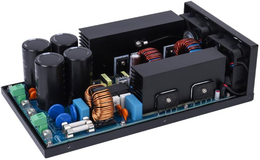
5 kW two-channel interleaved CCM PFC EVAL board
IKW40N65WR5, IDW60C65D1 and 1ED44175 in high frequency PFC application
Safety precautions
Safety precautions

Note:        Please note the following warnings regarding the hazards associated with development systems.

Table 1      Safety precautions
                      Warning: The DC link potential of this board is up to 400 VDC. When measuring voltage
                      waveforms by oscilloscope, high voltage differential probes must be used. Failure to do
                      so may result in personal injury or death.

                      Warning: The evaluation board contains DC bus capacitors which take time to
                      discharge after removal of the main supply. Before working on the drive system, wait
                      five minutes for capacitors to discharge to safe voltage levels. Failure to do so may
                      result in personal injury or death.
                      Warning: The evaluation board is connected to the grid input during testing. Hence,
                      high-voltage differential probes must be used when measuring voltage waveforms by
                      oscilloscope. Failure to do so may result in personal injury or death.

                      Caution: The heat sink and device surfaces of the evaluation or reference board may
                      become hot during testing. Hence, necessary precautions are required while handling
                      the board. Failure to comply may cause injury.

                      Caution: Only personnel familiar with the drive, power electronics and associated
                      machinery should plan, install, commission and subsequently service the system.
                      Failure to comply may result in personal injury and/or equipment damage.

                      Caution: The evaluation board contains parts and assemblies sensitive to
                      electrostatic discharge (ESD). Electrostatic control precautions are required when
                      installing, testing, servicing or repairing the assembly. Component damage may result
                      if ESD control procedures are not followed. If you are not familiar with electrostatic
                      control procedures, refer to the applicable ESD protection handbooks and guidelines.
                      Caution: A drive that is incorrectly applied or installed can lead to component damage
                      or reduction in product lifetime. Wiring or application errors such as undersizing the
                      motor, supplying an incorrect or inadequate AC supply, or excessive ambient
                      temperatures may result in system malfunction.
                      Caution: The evaluation or reference board is shipped with packing materials that
                      need to be removed prior to installation. Failure to remove all packing materials that
                      are unnecessary for system installation may result in overheating or abnormal
                      operating conditions.

User guide                                         3 of 41                                                  v1.0
                                                                                                      2021-03-05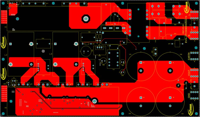
5 kW two-channel interleaved CCM PFC EVAL board
IKW40N65WR5, IDW60C65D1 and 1ED44175 in high frequency PFC application
Table of contents

Table of contents
About this document ....................................................................................................................... 1
Important notice ............................................................................................................................ 2
Safety precautions.......................................................................................................................... 3
Table of contents ............................................................................................................................ 4
1        The board at a glance .............................................................................................................. 5
1.1           Interleaved PFC ....................................................................................................................................... 5
1.2           Block diagram of the EVAL-PFC5KIKWWR5SYS ...................................................................................... 6
2     System and functional description ........................................................................................... 8
2.1        General overview ..................................................................................................................................... 8
2.1.1         UCC28070 - analogy controller .......................................................................................................... 9
2.1.2         IKW40N65WR5 - fast switching WR5 IGBT ......................................................................................... 9
2.1.3         IDW60C65D1 – rapid1 power silicon diode........................................................................................ 9
2.1.4         1ED44175 - low side gate driver ....................................................................................................... 10
2.2        Board specifications .............................................................................................................................. 10
3        System design.......................................................................................................................11
3.1           Schematics ............................................................................................................................................ 11
3.2           Layout .................................................................................................................................................... 17
3.3           Bill of material ....................................................................................................................................... 20
3.4           Connector details .................................................................................................................................. 24
4        System performance .............................................................................................................25
4.1           Efficiency and PFC measurements ....................................................................................................... 25
4.2           Start-up behavior .................................................................................................................................. 26
4.3           Input current and inductor current cancellation ................................................................................. 27
4.4           Switching performance of IGBT at steady state ................................................................................... 30
4.5           Output ripple voltage ............................................................................................................................ 31
4.6           Input voltage and input current............................................................................................................ 33
4.7           Load step tests ...................................................................................................................................... 34
4.8           Thermal measurements ........................................................................................................................ 36
5        Conclusions ..........................................................................................................................38
6        References and appendices ....................................................................................................39
6.1           Abbreviations and definitions ............................................................................................................... 39
6.2           References ............................................................................................................................................. 39
6.3           Additional information .......................................................................................................................... 39
Revision history.............................................................................................................................40

User guide                                                                       4 of 41                                                                           v1.0
                                                                                                                                                             2021-03-05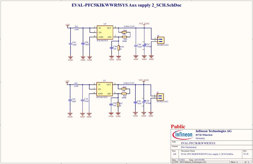
5 kW two-channel interleaved CCM PFC EVAL board
IKW40N65WR5, IDW60C65D1 and 1ED44175 in high frequency PFC application
The board at a glance

 1             The board at a glance
This section of the UG-2021-06 describes the basic concepts about interleaved PFC and a brief introduction about
the design of EVAL-PFC5KIKWWR5SYS board.

1.1             Interleaved PFC
The standard boost converter is the most popular topology for power factor correction due to a simple control
of the input current while keeping the output voltage constant. For medium power levels, increasing the output
power and improving overall efficiency leads to the use of several converters in a parallel connection, such as
two channles or three channels connected in parallel. Furthermore, if the switches operate at two-channel
connection with 180° out of phase or three-channel connection with 120° out of phase, the interleaved operation
shares the same load capacitors and reduces input current ripple significantl. It also eases the burden of filtering
conducted EMI noise and helps reduce the EMI filter and CIN sizes.
This approach has several other benefits, such as ease of implementation, the use of more, but smaller
components and better heat distribution. Simultaneously, the output capacitor current ripple is also decreased
and evenly distributed in eachchannel, which can extend the life of the capacitors, help to reduce its size and
cost. Compared to a single boost converter, the inductors in interleaved PFC handle only half or one-third of the
current, inductors with much lower inductance values can reach the same high power, and lower inductance
means smaller inductors and higher power density for a given power rating.
Figure 1 is an example of two-channel interleaved PFC. Its detailed operation principles and key waveforms are
shown in Figure 2.

                                          IL1                                  ID1

                                          IL2
                                                                               ID2
       Iin

                                                             IQ1         IQ2

                                                                                       Ic                     Iout

Figure 1        Block diagram of two-channel interleaved PFC

User guide                                             5 of 41                                                  v1.0
                                                                                                          2021-03-05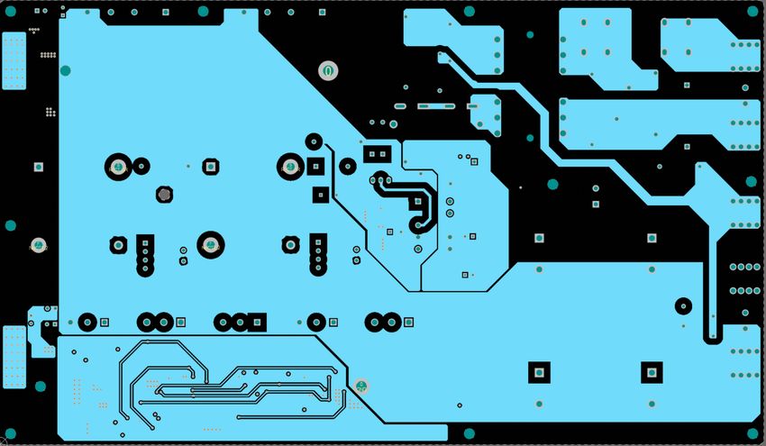
5 kW two-channel interleaved CCM PFC EVAL board
IKW40N65WR5, IDW60C65D1 and 1ED44175 in high frequency PFC application
The board at a glance

Figure 2        Principles of operation for the two-channel interleaved PFC

1.2             Block diagram of the EVAL-PFC5KIKWWR5SYS
As we know, reduction the size of power converters by increasing switching frequency and reducing magnetic
component size is a goal that has been pursued for decades. This is especially true when using IGBTs in a
switching mode power supply.Higher switching frequency, means smaller size and lower cost. A high
performance IGBT is the key component in helping customers to gain a bigger market share. Fortunately,
Infineon’s WR5 IGBT is specifically optimized for full-rated hard-switching applications with an excellent
price/performance ratio, and is recommended for use in AC-DC PFC stage for cost-sensitive applications. The
EVAL-PFC5KIKWWR5SYS is an evaluation board for demonstrating the switching performance of TRENCHSTOP™
5 WR5 IGBT IKW40N65WR5 with high switching frequencies up to 60 kHz in interleaved PFC application.
The block diagram of EVAL-PFC5KIKWWR5SYS is depicted in Figure 3, which shows the high-performance analogy
controller UCC28070, TRENCHSTOP™ 5 IGBT IKW40N65WR5, low side gate driver 1ED44175 and rapid1 power
silicon diode IDW60C65D1.
This reference design includes:
•   Two-channel boost converters
•   High-speed 650 V, 40 A reverse conducting TRENCHSTOP™ 5 WR5 IGBT in TO-247 package
•   Gate driver ICs for WR5 IGBTs
•   Rapid1 power silicon diode for boost rectification
•   Loss-free current monitering for switching current
•   15 V auxiliary power supply
•   Connectors for easy setup

User guide                                               6 of 41                                        v1.0
                                                                                                  2021-03-05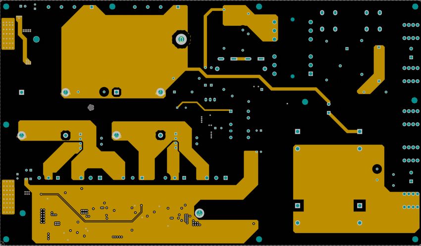
5 kW two-channel interleaved CCM PFC EVAL board
IKW40N65WR5, IDW60C65D1 and 1ED44175 in high frequency PFC application
The board at a glance

•   External force cooling for high power application

                           IL1                                                ID1

                                                               IDW60C65D1

                          IL2
                                                                              ID2

                                           IQ1                          IQ2

                      IKW40N65WR5                                                   Ic   Iout
                                                                      IKW40N65WR5

                                           CT1                          CT2

                      1ED44175                   1ED44175

                        GDA         CSA            GDB         CSB

                              UCC28070 interleaved CCM PFC controller
Figure 3        Block diagram of EVAL-PFC5KIKWWR5SYS

User guide                                                  7 of 41                                   v1.0
                                                                                                2021-03-05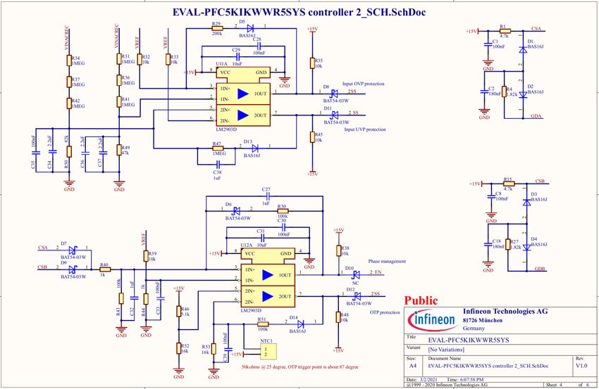
5 kW two-channel interleaved CCM PFC EVAL board
IKW40N65WR5, IDW60C65D1 and 1ED44175 in high frequency PFC application
System and functional description

2               System and functional description
2.1             General overview
EVAL-PFC5KIKWWR5SYS is a referene design for 5 kW interleaved PFC for, but not limited to, floor-standing air
conditioners in major home appliances.

Figure 4        EVAL-PFC5KIKWWR5SYS board view

The EVAL-PFC5KIKWWR5SYS evaluation board design characteristics include:

Board performance:
•   High power factor, PF>0.995
•   Low THDi
•   High efficiency

Control technology incorporated:
•   CCM (continuous conduction mode) average current control
•   Frequency-dithering for enhanced EMI reduction

Fault protection:
•   Input undervoltage protection and overvoltage protection
•   Output overvoltage protection
•   Open-circuit protection on AC input and DC output
•   Cycle-by-cycle peak current limiting
•   Thermal shutdown for power semiconducters

User guide                                           8 of 41                                                v1.0
                                                                                                      2021-03-05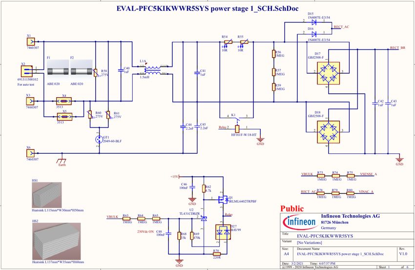
5 kW two-channel interleaved CCM PFC EVAL board
IKW40N65WR5, IDW60C65D1 and 1ED44175 in high frequency PFC application
System and functional description

2.1.1            UCC28070 - analogy controller
Infineon does not have a dedicated interleaved PFC controller, so we chose a UCC28070 from TI, which is a
popular choice in this field. Figure 5 is a simplified application diagram with UCC28070.

Figure 5         Simplified application diagram of UCC28070

2.1.2            IKW40N65WR5 - fast switching WR5 IGBT
IKW40N65WR5 is a high speed 650 V, 40 A reverse-conducting TRENCHSTOP™ 5 WR5 IGBT in TO-247 package. It
is optimized for hard switching applications with a best price/performance ratio, and it is a good fit with
mainstream designs of FSW > 20 kHz. The IKW40N65WR5 features the following key characteristics:

•   Very low VCEsat of 1.35 V @25°C
•   Low Etot
•   Soft recovery and low Qrr for diode
•   Good R(G)off controllability
•   Low T j & T c for lower heatsink and cooling costs

2.1.3            IDW60C65D1 – rapid1 power silicon diode
IDW60C65D1 is a 650 V/ 60 A rapid1 diode, emitter controlled power silicon diode in common cathode
configuration and in a TO-247 package, allowing design optimization for more compact dimensions, easier
assembly and consequently lower costs. Here is summary of its features:
•   Highest softness-factor for ultimate softness and low EMI filtering
•   1.35 V temperature-stable forward voltage (VF)
•   Lowest Irrm to provide lowest turn-on losses on the boost switch

User guide                                               9 of 41                                        v1.0
                                                                                                  2021-03-05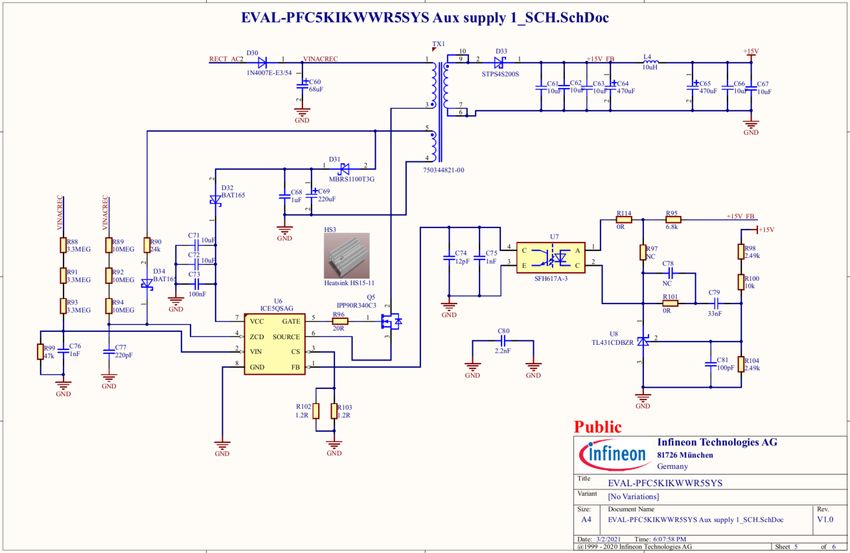
5 kW two-channel interleaved CCM PFC EVAL board
IKW40N65WR5, IDW60C65D1 and 1ED44175 in high frequency PFC application
System and functional description

2.1.4             1ED44175 - low side gate driver
    1ED44175 is an EiceDRIVER™ 25 V single-channel low-side non-inverting gate driver for IGBT with typical 2.6 A
    source and sink currents in a tiny 6-lead PG-SOT23 package. 1ED44175N01B provides cost and space savings by
    integrating the comparator. The new low-side gate driver utilizes Infineon’s proprietary latch immune CMOS
    technologies to enable a rugged monolithic construction while achieving best-in-class fault reporting accuracy
    with an OCP threshold tolerance of +/-5%. Its features are listed as follows:
•     -0.246 V over current threshold with accurate ±5% tolerance
•     Over current detection with negative voltage input
•     Single pin for fault output and enable
•     Programmable fault-clear time
•     Under voltage lockout for IGBTs
•     CMOS Schmitt-triggered inputs
•     3.3 V, 5 V and 15 V input logic compatible
•     Output in phase with input
•     -10 Vdc negative input capability of OCP pin
•     3 kV ESD HBM

2.2               Board specifications
Table 2 depicts the key specifications of the reference design used in the EVAL-PFC5KIKWWR5SYS.

Table 2           EVAL-PFC5KIKWWR5SYS specifications
 NO.         Parameters                              Symbol                             Value
 1           Output power                            Pout                               5000 watt
 2           Input voltage range (rms)               Vin                                180 Vac to 264 Vac
 3           Input frequency range                   f                                  50 Hz or 60 Hz
 4           Ouput voltage                           VDC                                400 V
 5           Output ripple voltage                   Vripple                            20 V
 6           Inductance                              L1, L2                             53 µH
 7           Switching frequency                     Fs                                 60 kHz

User guide                                                10 of 41                                             v1.0
                                                                                                         2021-03-05
5 kW two-channel interleaved CCM PFC EVAL board
IKW40N65WR5, IDW60C65D1 and 1ED44175 in high frequency PFC application
System design
3 System design
To meet individual customer requirements and make the EVAL-PFC5KIKWWR5SYS evaluation board a basis for
development or modification, all necessary technical data like schematics, layout and components are included
in this chapter.
The EVAL-PFC5KIKWWR5SYS consisits of three blocks: power stage, controller circuit and auxiliary supply, all of
which are on the same board. All surface mounted devices are mounted on the bottom layer, enabling customers
to modifiy parameters if necessary.
3.1 Schematics
There are a total of 6 schematic diagrams in its design. The figures below describe their functions respectively.
Figure 6 shows the converter’s EMI filter, soft start control, and diode rectifers. Connectors X1, X3 and X6 connect
to grid line, neutral and ground respectively. Three MOVs (R58, R60 and R61) and gase discharge tube GT1 consist
of the surge protection circuit. R54 and R55 limit input current ramp slope at startup. Once the voltage of output
capacitors is up to about 230V, the K1 relay turns on and bypasses R54 and R55. At this point, the PFCconverter
works with high efficiency.
User guide 11 of 41 v1.0
2021-03-055 kW two-channel interleaved CCM PFC EVAL board
IKW40N65WR5, IDW60C65D1 and 1ED44175 in high frequency PFC application
System design
Figure 6 EMI filter, soft start control, and rectifiers of EVAL-PFC5KIKWWR5SYS
In Figure 7, two-channel boost converters connect in parallel with 180° out-of-phase control. Each channel has a
WR5 IGBT IKW40N65WR5 as main switch, a rapid1 fast-recovery diode IDW60C65D1 with common cathode as
boost diodes for both channels, in paratical applications, customers can also select two seprated silicon fast-
recovery diodes or two SiC diodes to replace this common cathode diode, and put them as D21 and D22. A current
transformer monitors the IGBT current for normal operation and cycle-by-cycle current limiting. Each gate driver
User guide 12 of 41 v1.0
2021-03-055 kW two-channel interleaved CCM PFC EVAL board
IKW40N65WR5, IDW60C65D1 and 1ED44175 in high frequency PFC application
System design
1ED44715 matches one IGBT. Two boost inductors with NPH-L material comes from POCO have better
performance than inductors with traditional powder materials.
Figure 7 Interleaved PFC power stage of EVAL-PFC5KIKWWR5SYS
User guide 13 of 41 v1.0
2021-03-055 kW two-channel interleaved CCM PFC EVAL board
IKW40N65WR5, IDW60C65D1 and 1ED44175 in high frequency PFC application
System design
Figure 8 depicts the UCC28070 analog control and its parameter settings with external resistors and capacitors.
Potentiometer R115 sets converter switching frequency, it is very easy for customer to adjust switching
frequency.
Figure 8 UCC28070 parameter settings of EVAL-PFC5KIKWWR5SYS
User guide 14 of 41 v1.0
2021-03-055 kW two-channel interleaved CCM PFC EVAL board
IKW40N65WR5, IDW60C65D1 and 1ED44175 in high frequency PFC application
System design
Great care was taken to select the proper value for RC filters applied to VSENSE and VINAC, as it may be beneficial in
a noisy environment to avoid the destabilizing effects of excess noise on these inputs. If applied, the RC time-
constant for these two pins should not exceed 100 us. More information about how to control the UCC28070 with
external components can be found in [1].
Figure 9 shows the fault protection of this board: thermal shutdown of the power semiconductors is
implemented by an external comparator, in case the cooling fans fixed on the mechanical box do not work or fail,
the resistance of NTC fixed on heatsink decreases dramatically, and the SS pin of UCC28070 is pulled-down to
ground, in which case both gate signals are disabled.
Figure 9 Protections of EVAL-PFC5KIKWWR5SYS
User guide 15 of 41 v1.0
2021-03-055 kW two-channel interleaved CCM PFC EVAL board
IKW40N65WR5, IDW60C65D1 and 1ED44175 in high frequency PFC application
System design
Because UCC28070 already has an integrated output over voltage protection via the continuous monitoring of
VVSENSE, the intput over-voltage protection and under-voltage protection in this converter are implemented by an
external comparator, both of which are also connected to the SS pin of UCC28070.
Figure 10 Auxiliary supply of EVAL-PFC5KIKWWR5SYS
Figure 10 depicts the auxiliary supply of the evaluation board, supplying the voltage to the controller circuit, gate
drivers and cooling fans. ICE5QSAG [2] is a QR mode controller for soft switching operation of Q5, it helps to
User guide 16 of 41 v1.0
2021-03-055 kW two-channel interleaved CCM PFC EVAL board
IKW40N65WR5, IDW60C65D1 and 1ED44175 in high frequency PFC application
System design
increase system efficiency.For a simplifed design of the flyback transformer (TX1 in Figure 10), there is only one
secondary winding with an output voltage of 15 V, which is an optimized votage for driving IGBTs.
However, the maximum recommended voltage for cooling fans is 13.8V, therefore, as shown in Figure 11, two
LDO chips IFX1963 provide about 13.6 V voltage to fans directly, without fan speed regulation.
Figure 11 Low dropout regulator for fans of EVAL-PFC5KIKWWR5SYS
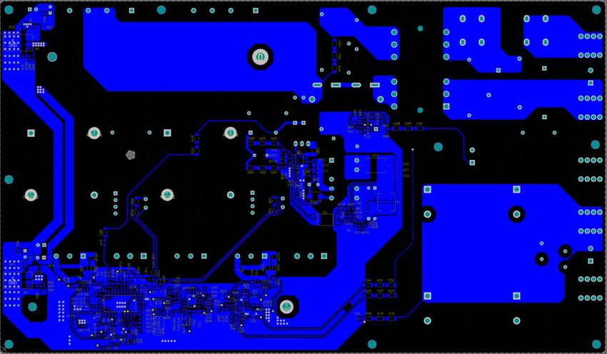
3.2 Layout
The layout of this evaluation board is helpful for customers to understand the placements of components and
the routing of wires for whole board. As a default, the PCB has four electrical layers with 70 µm of copper and
diemensions of 244 mm × 142 mm. The PCB board thickness is 2 mm. Please check Infineon’s website or contact
Infineon’s technical support team to obtain more detailed information and the latest Gerber files.
User guide 17 of 41 v1.0
2021-03-055 kW two-channel interleaved CCM PFC EVAL board
IKW40N65WR5, IDW60C65D1 and 1ED44175 in high frequency PFC application
System design
Figure 12 Top-layer routing of EVAL-PFC5KIKWWR5SYS
Figure 12 illustrates the top-layer routing of this evaluation board.
Figure 13 Mid-layer 1 routing of EVAL-PFC5KIKWWR5SYS
Figure 13 depicts the mid-layer 1 routing of this evaluation board.
User guide 18 of 41 v1.0
2021-03-055 kW two-channel interleaved CCM PFC EVAL board
IKW40N65WR5, IDW60C65D1 and 1ED44175 in high frequency PFC application
System design
Figure 14 Mid-layer 2 routing of EVAL-PFC5KIKWWR5SYS
Figure 14 shows the mid-layer 2 routing of this evaluation board.
Figure 15 Bottom-layer routing of EVAL-PFC5KIKWWR5SYS
Figure 15 illustrates the bottom-layer routing of this evaluation board.
User guide 19 of 41 v1.0
2021-03-055 kW two-channel interleaved CCM PFC EVAL board
IKW40N65WR5, IDW60C65D1 and 1ED44175 in high frequency PFC application
System design
3.3 Bill of material
The complete bill of material is available on the download section of the Infineon homepage. A log-in is
required to download this material.
Table 3 BOM of evaluation board
Ref
Quantity Value Description Manufacturer Manufacturer P/N
Designator
15 C1, C5, C6, C8, 100nF Chip Monolithic Ceramic MuRata GRM188R71E104KA01,
C13, C28, C30, Capacitor
C33, C35, C39,
C46, C48, C58,
C59, C73
2 C2, C18 180nF Chip Monolithic Ceramic MuRata GCM188R71E184JA55
Capacitor
6 C3, C9, C27, 1nF Chip Monolithic Ceramic MuRata GRM188R71E102KA01,
C76, C89, C90 Capacitor
4 C4, C34, C36, 2.2uF Chip Monolithic Ceramic MuRata GRM188R61E225KA12
C37 Capacitor
18 C7, C29, C31, 10uF Commerical Grade TDK Corporation C3216X7R1E106K160AB
C56, C57, C61, Multilayer Ceramic Chip
C62, C63, C66, Capacitor
C67, C70, C71,
C72, C82, C83,
C84, C86, C88
2 C10, C81 100pF Multilayer Ceramic Chip TDK Corporation C1608X7R1H101M
Capacitor, C Series,
Commercial Grade,
General
3 C11, C21, C23 2.2nF Chip Monolithic Ceramic MuRata GRM188R71E222KA01
Capacitor
1 C12 51nF Chip Monolithic Ceramic MuRata GCM188R71E473KA37
Capacitor
4 C14, C32, C38, 1uF Chip Monolithic Ceramic MuRata GRM188R71E105KA12
C68 Capacitor
1 C15 470nF Chip Monolithic Ceramic MuRata GRM188R71C474KA88
Capacitor
2 C16, C91 330pF Chip Monolithic Ceramic MuRata GRM216R71H331KA01
Capacitor
3 C17, C53, C54 330pF Chip Monolithic Ceramic MuRata GRM188R71H331KA01
Capacitor
4 C19, C20, C25, 470pF Chip Monolithic Ceramic MuRata GRM188R71H471KA01
C26 Capacitor
2 C22, C24 560pF Chip Monolithic Ceramic MuRata GRM1885C1E561JA01
Capacitor
2 C40, C41 1uF Metallized Polypropylene TDK Corporation B32923C3105M000
Film Capacitor
1 C42 1uF Metallized Polyester Film Epcos B32522N6105K000
Capacitor
1 C43 NC Metallized Polyester Film Epcos B32522N6105K000
Capacitor
5 C44, C45, C47, 2.2nF AC Line Rated Ceramic Vishay 440LD22-R
C55, C80 Disc Capacitor Class X1,
760 VAC / Class Y1, 500
VAC
4 C49, C50, C51, 680uF CAP / ELCO / 680uF / Aishi ELP2WM681R60KT
C52 450V / 20% / - / -40℃ to
105℃ / 10.00mm Pitch X
35.00mm Dia X 62.00 mm
H body / - / -
1 C60 68uF Miniature Aluminum Aishi EHL2WM680W50OT
Electrolytic Capacitor
4 C64, C65, C85, 470uF Aluminum Electrolytic Aishi SPD1CM102G12O00RAXX
C87 Capacitor / FC Series X
1 C69 220uF Miniature Aluminium Aishi EML1EM221F09OT
Electrolytic Capacitor
1 C74 12pF Chip Monolithic Ceramic MuRata GRM31A5C2H120JW01
Capacitor
User guide 20 of 41 v1.0
2021-03-055 kW two-channel interleaved CCM PFC EVAL board
IKW40N65WR5, IDW60C65D1 and 1ED44175 in high frequency PFC application
System design
Ref
Quantity Value Description Manufacturer Manufacturer P/N
Designator
1 C75 1nF Chip Monolithic Ceramic MuRata GRM319R71H102JA01
Capacitor
1 C77 220pF Chip Monolithic Ceramic MuRata GRM188R71H221KA01
Capacitor
1 C78 NC Multilayer Ceramic Chip TDK Corporation C1608X7R1H101M
Capacitor, C Series,
Commercial Grade,
General
1 C79 33nF Chip Monolithic Ceramic MuRata GRM188R71E333JA01
Capacitor
2 CT1, CT2 750344822-00 Transformer, 10.50mH, Wurth Elektronik 750344822-00
Turn Ratio 400:1
13 D1, D2, D3, D4, BAS16J Silicon Switching Diode Nexperia BAS16J
D5, D13, D14,
D23, D24, D25,
D26, D28, D29
6 D6, D7, D8, D9, BAT54-03W Silicon Schottky Diode Infineon BAT54-03W
D11, D12 Technologies
1 D10 NC Silicon Schottky Diode Infineon BAT54-03W
Technologies
3 D15, D16, D30 1N4007E-E3/54 General Purpose Plastic Vishay 1N4007E-E3/54
Rectifier
2 D17, D18 GBJ2508-F Glass Passivated Bridge Micro Commercial GBJ2508-F
Rectifier 600V Components
1 D19 IDW60C65D1 650 V rapid 1 Diode, IF Infineon IDW60C65D1
30/60A,TO247-3 Technologies
1 D20 STTH10LCD06FP Turbo2 Ultrafast High STMicroelectronic STTH10LCD06FP
Voltage Rectifier For Flat s
Panel Displays
2 D21, D22 NC 650 V rapid 1 Diode, Infineon IDW30E65D1
30A, TO247-3 Technologies
1 D27 BAV99 High-Speed Switching Nexperia BAV99
Diode
1 D31 MBRS1100T3G Schottky Power Rectifier ON MBRS1100T3G
Semiconductor
2 D32, D34 BAT165 Medium Power AF Infineon BAT165
Schottky Diode Technologies
1 D33 STPS4S200S Surface Mount Schottky STMicroelectronic STPS4S200S
Barrier Rectifier s
2 F1, F2 12.8mR Fast-Acting Fuse Conquer ABE 020
Cartridge, 20A/250V
1 GT1 2049-60-BLF RES / STD / - / - / 30% / - / Bourns 2049-60-BLF
-30℃ to 85℃ / 12.80mm
pitch, 6.00 mm L X 8.00
mm W, 8.3 mm H body / -
/-
1 HS1 Heatsink Heatsink - Heatsink
L115mm*W30mm*H50m L115mm*W30mm*H50m L115mm*W30mm*H50mm
m m
1 HS2 Heatsink Heatsink - Heatsink
L137mm*W35mm*H60m L137mm*W35mm*H60m L137mm*W35mm*H60mm
m m
1 HS3 Heatsink HS15-11 Heatsink L15*W11 - Heatsink HS15-11
1 K1 HF161F-W/18-HT Solar Relay, Applicable to HongFa HF161F-W/18-HT
inverter used for
photovoltaic power
generation systems
1 L1 1.5mH Common Mode Power Wurth Elektronik 7448063801
Line Choke
2 L2, L3 85uH IND / STD / 85uH / - / 10% POCO PI200273V1
/ - / 16mR / THT /
Inductor, THT, 4 pin,
54.00 mm L X 32.00 mm
W X 56.00 mm H body /
THT / -
1 L4 10uH IND / STD / 10uH / 4A / Wurth Elektronik 744314101
20% / -40℃ to 150℃ /
33mR / SMD / Inductor,
SMD, 6.90mm L X
User guide 21 of 41 v1.0
2021-03-055 kW two-channel interleaved CCM PFC EVAL board
IKW40N65WR5, IDW60C65D1 and 1ED44175 in high frequency PFC application
System design
Ref
Quantity Value Description Manufacturer Manufacturer P/N
Designator
6.90mm W X 5.00mm H
body / SMD / -
2 L5, L6 220R Chip Ferrite Bead Wurth Elektronik 742792031
1 NTC1 AYN-MF56-503F-3950FB- Header, 2-Pin AYN-MF56-503F-3950FB-
28#-100 28#-100
2 P1, P2 66100211622 CONNECTOR HEADER Wurth Elektronik 66100211622
VERT 2POS 2.54MM
1 Q1 IRLML6402TRPBF HEXFET P-Channel Infineon IRLML6402TRPBF
Power MOSFET, 20V, Technologies
3.7A
2 Q2, Q3 IKW40N65WR5 High speed fast IGBT in Infineon IKW40N65WR5
TRENCHSTOPTM 5 Technologies
technology, VCE 650V, IC
40A
1 Q5 IPP90R340C3 900V CoolMOS C3 Power Infineon IPP90R340C3
Transistor, RDS(on) Technologies
340mOhm
3 R1, R15, R81 4.7k General Purpose Chip Yageo RC0603FR-074K7L
Resistor
4 R2, R14, R108, 0R 0R/75V Panasonic ERJ3GEY0R00V
R109
1 R3 NC Standard Thick Film Chip Vishay CRCW0603115KFK,
Resistor
1 R11 NC Standard Thick Film Chip Vishay CRCW060310K0FK
Resistor
1 R97 NC Standard Thick Film Chip Vishay CRCW06031K20FK
Resistor
2 R4, R27 1.82k Standard Thick Film Chip Vishay CRCW06031K82FK
Resistor
1 R5 3MEG Standard Thick Film Chip Vishay CRCW06033M00FK
Resistor
2 R6, R50 82k Standard Thick Film Chip Vishay CRCW060382K0FK
Resistor
2 R7, R19 22.6k Standard Thick Film Chip Vishay CRCW060322K6FK
Resistor
3 R8, R66, R67 1k Standard Thick Film Chip Vishay CRCW12061K00FK
Resistor
1 R9 1.5k Standard Thick Film Chip Vishay CRCW06031K50FK
Resistor
8 R10, R32, R33, 10k Standard Thick Film Chip Vishay CRCW060310K0FK
R35, R38, R45, Resistor
R48, R100
1 R12 118k Standard Thick Film Chip Vishay CRCW0603118KFK
Resistor
1 R13 1k 1k/200V/1% TT Electronics ASC1206-1K0FT5
1 R16 124k Standard Thick Film Chip Vishay CRCW0603124KFK
Resistor
1 R17 33k Standard Thick Film Chip Vishay CRCW060333K0FK
Resistor
1 R18 84.5k Standard Thick Film Chip Vishay CRCW060384K5FK
Resistor
4 R20, R21, R22, 62R Standard Thick Film Chip Vishay CRCW121062R0FK
R23 Resistor
1 R24 3.65k Standard Thick Film Chip Vishay CRCW06033K65FK
Resistor
2 R25, R26 5.62k Standard Thick Film Chip Vishay CRCW06035K62FK
Resistor
1 R28 5.49k Standard Thick Film Chip Vishay CRCW06035K49FK
Resistor
1 R29 200k Standard Thick Film Chip Vishay CRCW0603200KFK
Resistor
3 R30, R43, R51 100k General Purpose Chip Yageo RC0603FR-07100KL
Resistor
18 R31, R34, R36, 1MEG Standard Thick Film Chip Vishay CRCW12061M00FK
R37, R41, R42, Resistor
R56, R57, R59,
R63, R64, R65,
R73, R74, R75,
R78, R79, R80
User guide 22 of 41 v1.0
2021-03-055 kW two-channel interleaved CCM PFC EVAL board
IKW40N65WR5, IDW60C65D1 and 1ED44175 in high frequency PFC application
System design
Ref
Quantity Value Description Manufacturer Manufacturer P/N
Designator
1 R39 10k General Purpose Chip Yageo RC1206FR-0710KL
Resistor
2 R40, R44 1k Standard Thick Film Chip Vishay CRCW06031K00FK
Resistor
1 R46 5.1k Standard Thick Film Chip Vishay CRCW06035K10FK
Resistor
1 R47 1MEG Standard Thick Film Chip Vishay CRCW06031M00FK
Resistor
2 R49, R99 47k Standard Thick Film Chip Vishay CRCW060347K0FK
Resistor
2 R52, R53 16k Standard Thick Film Chip Vishay CRCW060316K0FK
Resistor
2 R54, R55 10R NTC Thermistor for Inrush Epcos B57237S0100M000
Current Limiting
3 R58, R60, R61 275V Multi Pulse Handling SIOV Epcos B72220S0271K101
Metal Oxide Varistor
3 R62, R76, R77 4.7k Standard Thick Film Chip Vishay CRCW08054K70FK
Resistor
1 R68 33k 33k/50V/1% ROHM MCR03ERTF3302
Semiconductors
1 R69 470k Standard Thick Film Chip Vishay CRCW0603470KFK
Resistor
1 R70 220R Standard Thick Film Chip Vishay CRCW0805220RFK
Resistor
2 R71, R72 5.1R Standard Thick Film Chip Vishay CRCW12065R10FK
Resistor
1 R82 4.7k Standard Thick Film Chip Vishay CRCW12064K70FK
Resistor
2 R83, R84 30k Standard Thick Film Chip Vishay CRCW060330K0FK
Resistor
2 R85, R86 680R Standard Thick Film Chip Vishay CRCW0603680RFK
Resistor
2 R87, R105 3k 3k/50V/1% ROHM MCR03EZPFX3001
Semiconductors
3 R88, R91, R93 3.3MEG Standard Thick Film Chip Vishay CRCW12063M30FK
Resistor
3 R89, R92, R94 10MEG Standard Thick Film Chip Vishay CRCW120610M0FK
Resistor
1 R90 24k Standard Thick Film Chip Vishay CRCW060324K0FK
Resistor
1 R95 6.8k General Purpose Chip Yageo RC0805FR-076K8L
Resistor
1 R96 20R Standard Thick Film Chip Vishay CRCW120620R0FK
Resistor
2 R98, R104 2.49k Standard Thick Film Chip Vishay CRCW06032K49FK
Resistor
1 R101 0R Standard Thick Film Chip Vishay CRCW06030000Z0
Resistor
2 R102, R103 1.2R Standard Thick Film Chip Vishay CRCW12061R20FK
Resistor
2 R106, R107 3R 3R/0.5W/1% Panasonic ERJ8BQF3R0V
1 R114 0R Standard Thick Film Chip Vishay CRCW08050000Z0
Resistor
1 R115 250k RES / VAR / 250k / Bourns 3314G-1-254E
250mW / 20% / 100ppm/K
/ -55℃ to 125℃ / 3 pin,
5.00mm L X 4.50mm W X
2.85mm H Body / SMD / -
1 TX1 750344821-00 Transformer 10-Terminal Würth Elektronik 750344821-00
EXT, THT, Horizontal, EE Midcom
Style Bobbins, EE20
1 U1 UCC28070DW PFC controller Texas Instruments UCC28070DW
2 U2, U8 TL431CDBZR Precision Programmable Texas Instruments TL431CDBZR
Reference
2 U3, U4 1ED44175N01B Gate Drivers LOW SIDE Infineon 1ED44175N01B
DRIVERS Technologies
2 U5, U9 IFX1963TEV 1.5A Low Dropout Linear Infineon IFX1963TEV
Voltage Regulator Technologies
User guide 23 of 41 v1.0
2021-03-055 kW two-channel interleaved CCM PFC EVAL board
IKW40N65WR5, IDW60C65D1 and 1ED44175 in high frequency PFC application
System design
Ref
Quantity Value Description Manufacturer Manufacturer P/N
Designator
1 U6 ICE5QSAG Quasi-Resonant PWM Infineon ICE5QSAG
Controller Technologies
1 U7 SFH617A-3 Optocoupler, Vishay SFH617A-3
Phototransistor Output,
High Reliability, 5300
VRMS, 110 °C Rated
2 U11, U12 LM2903D Dual differential Texas Instruments LM2903D
comparators
5 X1, X3, X6, X7, 7460307 WP-BUTR Redcube Press Wurth Elektronik 7460307
X9 Fit with Internal Thread
and Two Rows Pin-Plate
2 X2, X8 691311500102 Terminal Block, 2Pins, Wurth Elektronik 691311500102
5.08mm Pitch, Board to
Cable
4 X4, X5 3513 Through Hole 3AG Snap Conquer CQ-205S
In Fuse Clip
2 FAN1, FAN2 AFB0612EH-ABF00 Cooling fans Delta AFB0612EH-ABF00
3.4 Connector details
Table 4 Connectors
PIN Label Function
X1 Grid Line AC input of PFC, connect to grid line
X3 Grid Neutral AC input of PFC, connect to grid neutral
X6 Earth Protective earth
X7 PFC DC output Connect to load positive
X9 PFC Ground Connect to load negative
X2 Auto test For AC input auto test
X8 Auto test For PFC output auto test
User guide 24 of 41 v1.0
2021-03-055 kW two-channel interleaved CCM PFC EVAL board
IKW40N65WR5, IDW60C65D1 and 1ED44175 in high frequency PFC application
System performance
4 System performance
4.1 Efficiency and PFC measurements
All test conditions are based on a 25℃ ambient temperature
For the efficiency test it is important to monitor the voltage directly on the input connector X2 and output
connector X8.
All efficiency and PF are carried out with a “WT33E” Yokogawa power meter.
Figure 16 shows the overall efficiency of EVAL-PFC5KIKWWR5SYS including the aux supply for cooling fans at
different input voltages between 180 VAC and 264 VAC. The efficiency curves show that WR5 IGBTcan support
customers to increase the PFC switching frequency with high effiency, even frequencies up to 60 kHz.
Efficiency
98,500%
97,500%
96,500%
Efficiency %
95,500%
94,500%
93,500%
92,500%
500 1000 1500 2000 2500 3000 3500 4000 4500 5000
Output power (watt)
180VAC 230VAC 264VAC
Figure 16 Efficiency of EVAL-PFC5KIKWWR5SYS
Figure 17 shows the power factor curve at different loads and different AC input voltages. As shown, even at light
loads, the power factor is higher than 0.96. And an almost unity power factor is achieved, with values higher than
0.99 for loads above 30% of rated power.
User guide 25 of 41 v1.0
2021-03-055 kW two-channel interleaved CCM PFC EVAL board
IKW40N65WR5, IDW60C65D1 and 1ED44175 in high frequency PFC application
System performance
Power factor
1,0000
0,9950
0,9900
0,9850
0,9800
PF
0,9750
0,9700
0,9650
0,9600
0,9550
500 1000 1500 2000 2500 3000 3500 4000 4500 5000
Output power (watt)
180VAC 230VAC 264VAC
Figure 17 Power factor of EVAL-PFC5KIKWWR5SYS
4.2 Start-up behavior
Following connection to the grid, the auxiliary power supply starts, and the devices are supplied. During the
output capacitor pre-charging phase, as seen in Figure 6, both channels are bypassed by the D20- an ultrafast
high-voltage rectifier, and the inrush current is limited by two NTC resistors. Once output voltage reaches about
230 VDC, K1 relay turns on and two NTC are shorted, enabling the converter works with high efficiency.
The board is designed to start in both no load condition and full load condition. Figure 18 and Figure 19 show
the converter full-load start-up waveforms at VIN=180 VAC and VIN=264 VAC respectively.
Vout=Blue, VGE=Yellow, IL1=Red,VCE=Green
Figure 18 Full load start-up at VIN=180 VAC
User guide 26 of 41 v1.0
2021-03-055 kW two-channel interleaved CCM PFC EVAL board
IKW40N65WR5, IDW60C65D1 and 1ED44175 in high frequency PFC application
System performance
Vout=Blue, VGE=Yellow, IL1=Red,VCE=Green
Figure 19 Full load start-up at VIN=264 VAC
4.3 Input current and inductor current cancellation
The next six waveforms show the input AC current and two inductor current waveforms of the converter at full
load. The interleaving operation is clear and the two-channel currents are phase-shifted 180°.
IIN= Green, IL1=Yellow, IL2=Red
Figure 20 Interleaving operation at full load at VIN=180 VAC
User guide 27 of 41 v1.0
2021-03-055 kW two-channel interleaved CCM PFC EVAL board
IKW40N65WR5, IDW60C65D1 and 1ED44175 in high frequency PFC application
System performance
IIN= Green, IL1=Yellow, IL2=Red,VIN=Blue
Figure 21 Detail view of interleaving operation at full load at VIN=180 VAC
IIN= Green, IL1=Yellow, IL2=Red
Figure 22 Interleaving operation at full load at VIN=230 VAC
User guide 28 of 41 v1.0
2021-03-055 kW two-channel interleaved CCM PFC EVAL board
IKW40N65WR5, IDW60C65D1 and 1ED44175 in high frequency PFC application
System performance
IIN= Green, IL1=Yellow, IL2=Red,VIN=Blue
Figure 23 Detail view of interleaving operation at full load at VIN=230 VAC
IIN= Green, IL1=Yellow, IL2=Red
Figure 24 Interleaving operation at full load at VIN=264 VAC
User guide 29 of 41 v1.0
2021-03-055 kW two-channel interleaved CCM PFC EVAL board
IKW40N65WR5, IDW60C65D1 and 1ED44175 in high frequency PFC application
System performance
IIN= Green, IL1=Yellow, IL2=Red,VIN=Blue
Figure 25 Detail view of interleaving operation at full load at VIN=264 VAC
4.4 Switching performance of IGBT at steady state
The design for this board is aimed at achieving high efficiency by using 650V TRENCHSTOP™ 5 WR5 IGBT
IKW40N65WR5 as the main switch in a high-frequency interleaved PFC application. Compared to Infineon’s H3
IGBT, the WR5 IGBT has lower conduction and switching losses, enabling the MOSFET to be replaced by a WR5
IGBT in up to 100 kHz applications.
The following three waveforms show switching performances of IKW40N65WR5 with the low side gate driver
1ED44175. For considering the driver’s current capability, in this design, the turn-on gate resistance for each
KW40N65WR5 is 5.1 Ω and turn-off resistance is 3 Ω.Smaller gate resistance for turn-on and turn-off helps to
decrease turn-on and turn-off losses of the IGBT. However, during the design process, there is always a trade-off
between achieving high efficiency and EMI. Customers need to make greater effort to reduce the noise by high
dv/dt and high di/dt in high-frequency applications.
VCE= Green, VGE=Yellow, IL1=Red,VOUT=Blue
Figure 26 Switching waveforms of IGBT at VIN=180 VAC at full load
User guide 30 of 41 v1.0
2021-03-055 kW two-channel interleaved CCM PFC EVAL board
IKW40N65WR5, IDW60C65D1 and 1ED44175 in high frequency PFC application
System performance
VCE= Green, VGE=Yellow, IL1=Red,VOUT=Blue
Figure 27 Switching waveforms of IGBT at VIN=200 VAC at full load (continue current at high point of
input voltage)
VCE= Green, VGE=Yellow, IL1=Red,VOUT=Blue
Figure 28 Switching waveforms of IGBT at VIN=200 VAC at full load (discontinue current at low point
of input voltage)
4.5 Output ripple voltage
Due to the limitation of the board size and cost considerations, there are only four output filter capacitors with a
total of 2720 uF placed at the output stage. For the next three waveforms with full load at different input voltages,
the permissible low-frequency ripple of the output voltage is smaller than 20 V, which meets design specifications
as well.
User guide 31 of 41 v1.0
2021-03-055 kW two-channel interleaved CCM PFC EVAL board
IKW40N65WR5, IDW60C65D1 and 1ED44175 in high frequency PFC application
System performance
VOUT=Blue, IIN= Red
Figure 29 PFC output ripple voltage at VIN=180 VAC at full load
VOUT=Blue, IIN= Red
Figure 30 PFC output ripple voltage at VIN=230 VAC at full load
User guide 32 of 41 v1.0
2021-03-055 kW two-channel interleaved CCM PFC EVAL board
IKW40N65WR5, IDW60C65D1 and 1ED44175 in high frequency PFC application
System performance
VOUT=Blue, IIN= Red
Figure 31 PFC output ripple voltage at VIN=264 VAC at full load
4.6 Input voltage and input current
The line current in the following figures are nearly perfect sinusoidal waves, in phase with the line voltage,
while the output voltage is regulated at 400 V at full load.
VIN=Blue, IIN= Red
Figure 32 PFC input voltage and input current at VIN=180 VAC at full load
User guide 33 of 41 v1.0
2021-03-055 kW two-channel interleaved CCM PFC EVAL board
IKW40N65WR5, IDW60C65D1 and 1ED44175 in high frequency PFC application
System performance
VIN=Blue, IIN= Red
Figure 33 PFC input voltage and input current at VIN=230 VAC at full load
VIN=Blue, IIN= Red
Figure 34 PFC input voltage and input current at VIN=264 VAC at full load
4.7 Load step tests
Figure 35 and Figure 36 illustrate the response of the PFC converter during a load step from no load to full load
with a voltage undershoot down to 352 VDC and 360 VDC, respectively. After such an abrupt load demand, the PFC
controller returns to regulation in around 60 ms.
User guide 34 of 41 v1.0
2021-03-055 kW two-channel interleaved CCM PFC EVAL board
IKW40N65WR5, IDW60C65D1 and 1ED44175 in high frequency PFC application
System performance
VOUT=Blue, IOUT= Green
Figure 35 Load step :0%→100% at VIN=180 VAC
VOUT=Blue, IOUT= Green
Figure 36 Load step :0%→100% at VIN=264 VAC
User guide 35 of 41 v1.0
2021-03-055 kW two-channel interleaved CCM PFC EVAL board
IKW40N65WR5, IDW60C65D1 and 1ED44175 in high frequency PFC application
System performance
VOUT=Blue, IOUT= Green
Figure 37 Load step :100%→0% at VIN=180 VAC
Figure 37 illustrates the response of the voltage control loop during a load step from 100% to 0% with a voltage
overshoot up to 425 V. A similar response can be observed at VIN = 230 VAC and VIN = 264 VAC.
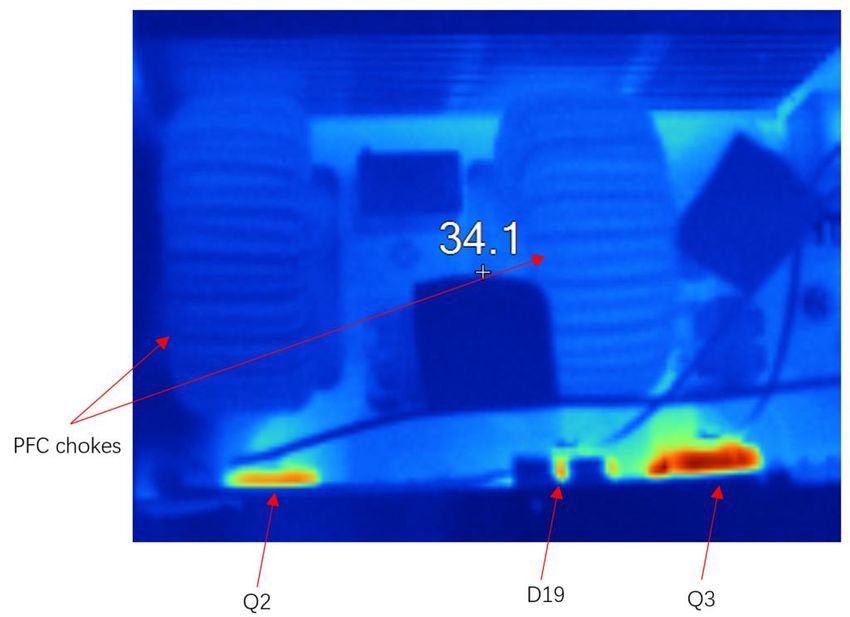
4.8 Thermal measurements
The board shown in this document (EVAL-PFC5KIKWWR5SYS) is provided with an enclosure. The implemented
thermal concept uses two low-power fans attached to two heatsinks, in which the power semiconductors
dissipate their generated losses.
User guide 36 of 41 v1.0
2021-03-055 kW two-channel interleaved CCM PFC EVAL board
IKW40N65WR5, IDW60C65D1 and 1ED44175 in high frequency PFC application
System performance
Figure 38 Thermal capture at room temperature at nominal input (180 V) and full load condition for
PFC operation
Due to two powerful fans in an enclosed environment, the PFC chokes are not the hotspot of the board, as can
be seen in Figure 38. One of WR5 IGBT (Q3) is the hottest power device on this board, which is far away from the
cooling fans. Accoding to temperature data collected by Keysight 34970A with thermal couples, as shown in
Table 5, the highest temperature of the IGBT is 84.2℃ at full load while input voltage is 180 VAC. Fortunately, in
floor-standing air-conditioner applications, its output power will be derated at low-input voltage, so, further
temperature data at half load is also shown in Table 5, while input voltage is 180 VAC, the highest temperature of
IGBT is only 45.9℃.
Table 5 Temperature of power semiconductors
Devices VIN=230 VAC, full load VIN=180 VAC, full load VIN=180 VAC, half load
Q2 (IKW40N65WR5) 51.7℃ 67.8℃ 39.8℃
D19 (IDW60C65D1) 61.6℃ 74.2℃ 40.3℃
Q3 (IKW40N65WR5) 62.1℃ 84.2℃ 45.9℃
User guide 37 of 41 v1.0
2021-03-055 kW two-channel interleaved CCM PFC EVAL board
IKW40N65WR5, IDW60C65D1 and 1ED44175 in high frequency PFC application
Conclusions
5 Conclusions
This user guide describes the implementation of an analog-controlled, single-phase, two-channel interleaved
PFC converter that operates in continuous conduction mode. This interleaved PFC converter achieves a peak
efficiency of 97.804% by using an Infineon 650 V TRENCHSTOP™ 5 WR5 IGBT IKW40N65WR5 and rapid1 power
silicon diode IDW60C65D1.
The EVAL-PFC5KIKWWR5SYS board has been tested using a programmable AC source and electronic load to
demonstrate the key performance and behaviors in PFC operation.
Customers can also furthe increase the switching frequency to decrease the size and cost of the inductors, or
extend the converter input voltage from 85 VAC to 264VAC. External parameter settings of resistors and capacitors
of UCC28070 are also needed as an optimizations to the new requirments.
User guide 38 of 41 v1.0
2021-03-055 kW two-channel interleaved CCM PFC EVAL board
IKW40N65WR5, IDW60C65D1 and 1ED44175 in high frequency PFC application
References and appendices
6 References and appendices
6.1 Abbreviations and definitions
Table 6 Abbreviations
Abbreviation Meaning
CE Conformité Européenne
EMI Electromagnetic interference
UL Underwriters Laboratories
BOM Bill of Material
QR Quasi-resonant
PF Power factor
POCO A Chinese powder core manufacturer
NPH-L A powder core material from POCO
6.2 References
[1] Texas instruments, “UCC28070 300W Interleaved PFC Pre-regulator Design Review (Rev. B)”, Application
Report, SLUA479B, August 2008.
[2] Infineon Technologies, “Fifth-generation QR design guide for ICE5QSAG and ICE5QRXXXXAX”, Application
Report, DG_201609_PL83_026, September 2017.
6.3 Additional information
In the following links you can find more detailed information about the used devices from Infineon.
⚫ TRENCHSTOP™ 5 WR5 IGBT IKW40N65WR5
⚫ Low-side gate driver 1ED44175N01B
⚫ Rapid1 power silicon diode IDW60C65D1
⚫ QR Flyback controller ICE5QSBG for auxliary supply
User guide 39 of 41 v1.0
2021-03-055 kW two-channel interleaved CCM PFC EVAL board
IKW40N65WR5, IDW60C65D1 and 1ED44175 in high frequency PFC application
Revision history
Revision history
Document Date of release Description of changes
version
V1.0 March 5,2021 User guide-initial release
User guide 40 of 41 v1.0
2021-03-05Trademarks
All referenced product or service names and trademarks are the property of their respective owners.
For further information on the product, technology,
Edition 2021-03-05 delivery terms and conditions and prices please
Published by contact your nearest Infineon Technologies office
(www.infineon.com).
Infineon Technologies AG
81726 Munich, Germany WARNINGS
Due to technical requirements products may contain
dangerous substances. For information on the types
in question please contact your nearest Infineon
© 2021 Infineon Technologies AG. Technologies office.
All Rights Reserved.
Except as otherwise explicitly approved by Infineon
Do you have a question about this Technologies in a written document signed by
authorized representatives of Infineon
document? Technologies, Infineon Technologies’ products may
Email: erratum@infineon.com not be used in any applications where a failure of the
product or any consequences of the use thereof can
reasonably be expected to result in personal injury.
Document reference
UG-2021-06You can also read