NJCAT TECHNOLOGY VERIFICATION - HydroDome (HD) Stormwater Separator Hydroworks, LLC May 2021
←
→
Page content transcription
If your browser does not render page correctly, please read the page content below
NJCAT TECHNOLOGY VERIFICATION

HydroDome (HD) Stormwater Separator

         Hydroworks, LLC

             May 2021
TABLE OF CONTENTS

List of Figures                                              ii

List of Tables                                               iii

1.     Description of Technology                              1

2.     Laboratory Testing                                     2
       2.1    Test Setup                                      3
       2.2        Hydraulic Testing                           5
       2.3        Removal Efficiency Testing                  5
       2.4        Scour Testing                               7
       2.5        Instrumentation and Measuring Techniques    7
       2.6        Data Management and Acquisition             10
       2.7        Quality Assurance and Control               11

3.     Performance Claims                                     12

4.     Supporting Documentation                               13
       4.1        Test Sediment PSD Analysis                  13
       4.2        Removal Efficiency Testing                  14
       4.3        Scour Test                                  26
       4.4        Hydraulics                                  30

5.     Design Limitations                                     32

6.     Maintenance                                            34

7.     Statements                                             35

8.     References                                             40

Verification Appendix                                         41

                                                                   i
LIST OF FIGURES

Figure 1      Hydroworks HydroDome…...............................................................................1

Figure 2      HydroDome Internal Components .................................................................…2

Figure 3      HydroDome HD 3 Test Unit Installed in Alden Flow Loop .........................…3

Figure 4      Plan View of Alden Flow Loop .........................................................................4

Figure 5      Photograph Showing Laboratory Flow Meters ..................................................8

Figure 6      Pressure Measurement Instrumentation .............................................................9

Figure 7      Photograph Showing Variable-Speed Auger Feeder .........................................9

Figure 8      Photograph Showing the Background Isokinetic Sampler ..............................10

Figure 9      Removal Efficiency Test Sediment PSD Curves .............................................14

Figure 10 Hydroworks HD3 Removal Efficiency Curve .................................................16

Figure 11 25% MTFR Measured Flow and Influent Concentrations ...............................18

Figure 12 50% MTFR Measured Flow and Influent Concentrations ...............................20

Figure 13 75% MTFR Measured Flow and Influent Concentrations ...............................22

Figure 14 100% MTFR Measured Flow and Influent Concentrations .............................24

Figure 15 125% MTFR Measured Flow and Influent Concentrations .............................26

Figure 16 Scour Test Sediment PSD Curves ...................................................................27

Figure 17 Scour Test Flow Data………………………...................................................28

Figure 18 Scour Test Background and Effluent Concentrations ......................................29

Figure 19 Measured Flow vs Water Elevations ...............................................................31

Figure 20 Calculated Outlet Losses..................................................................................32

                                                                                                                         ii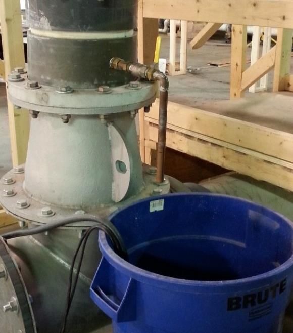
LIST OF TABLES

Table 1      NJDEP Target Test Sediment Particle Size Distribution ...................................6

Table 2      Removal Efficiency Test Sediment Particle Size Distribution .......................13

Table 3      Test Flow and Temperature Summary ............................................................ 15

Table 4      Injected Sediment Summary ........................................................................... 15

Table 5      Removal Efficiency Summary ........................................................................ 16

Table 6      25% MTFR Test Parameters and Collected Data ........................................... 17

Table 7      50% MTFR Test Parameters and Collected Data ............................................19

Table 8      75% MTFR Test Parameters and Collected Data ........................................... 21

Table 9      100% MTFR Test Parameters and Collected Data ..........................................23

Table 10 125% MTFR Test Parameters and Collected Data ..........................................25

Table 11 Scour Test Sediment Particle Size Distribution ...............................................27

Table 12 Scour Test Unadjusted Effluent Concentration Data .......................................30

Table 13 Recorded Flow and Elevation Data .................................................................31

Table A-1 MTFRs and Sediment Removal Intervals for HydroDome Models ............... 43

Table A-2 Standard Dimensions for HydroDome Models............................................... 44

                                                                                                                        iii
1.      Description of Technology

The Hydroworks HydroDome is a hydrodynamic stormwater separator. HydroDome comes
complete with an outlet pipe that slides into the outlet pipe of the structure and is then securely
attached to the structure wall. (Figure 1). All of the flow into the structure passes through the
HydroDome. There is no internal high flow bypass. Oil and floatable solids rise to the surface
and are immediately separated from the flow. Denser suspended solids settle and are captured in
the sump of the concrete structure.

                              Figure 1 Hydroworks HydroDome

The housing of the HydroDome itself is the primary measure to prevent any floatables or debris
from entering the HydroDome. Water flows into the HydroDome through submerged horizontal
openings at the bottom of the device (Figure 2). Water then enters a low flow path near the
center of the HydroDome before exiting through an orifice on the outlet side of the low flow
path. A debris screen (inlet protection) is located at the entrance to the low flow path as a
secondary measure to prevent any clogging from debris. A perforated plastic scour protection
plate at the bottom of the HydroDome minimizes scour by minimizing upward velocities/flow
from the structure floor during periods of higher flow. The perforations in the plate, much larger
than the largest particle tested, prevent sediment from settling on the plate.

                                                                                                 1
Figure 2 HydroDome Internal Components

The water level continues to rise in the structure depending on the rate of flow into the structure
and rate of flow out of the low flow path. If the flow rate into the HydroDome exceeds the low
flow path (siphon) rate the water level rises to a high flow weir (as tested in this study). Higher
flows are safely conveyed to the outlet over this weir. The weir is optional in other design
configurations where a controlled flow rate (only low flow rate) is desired.

       2.      Laboratory Testing

The test program was conducted at the Alden Research Laboratory, Inc. (Alden), Holden,
Massachusetts, under the direct supervision of Alden’s senior stormwater engineer, James
Mailloux. Alden has performed verification testing on approximately twenty hydrodynamic
separator and filtration Manufactured Treatment Devices (MTDs) for multiple manufacturers

                                                                                                 2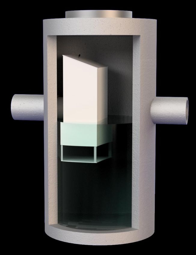
under various state and federal testing protocols. Water quality samples collected during this
testing process were analyzed in Alden’s Calibration Laboratory, which is ISO 17025 accredited.

Laboratory testing was done in accordance with the New Jersey Department of Environmental
Protection “Laboratory Protocol to Assess Total Suspended Solids Removal by a Hydrodynamic
Sedimentation Manufactured Treatment Device” (January 2013a) (NJDEP Hydrodynamic
Protocol). Prior to starting the performance testing program, a quality assurance project plan
(QAPP) was submitted to, and approved by, the New Jersey Corporation for Advanced
Technology (NJCAT).

       2.1   Test Setup

The laboratory test used a full-scale HydroDome (model HD 3) installed in a three (3) foot
diameter by nine (9) foot high plastic cylindrical test device. The HD 3 has a sump depth of 5 ft
and a sump area of 7.07 ft2. Aluminum inlet and outlet pipes, 18-inch in diameter, were oriented
along the centerline of the unit, with the inverts located 60 inches above the sump floor. The
100% and 50% sediment sump storage depths were 12 inches and 6 inches, respectively. A
photograph of the installed unit is shown on Figure 3.

             Figure 3 HydroDome HD 3 Test Unit Installed in Alden Test Loop

                                                                                               3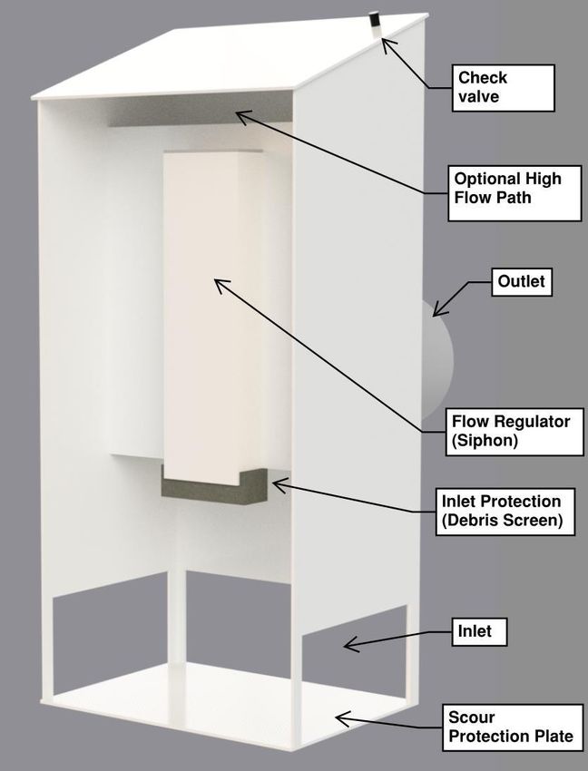
The HD 3 test unit was installed in the Alden test loop, shown on Figure 4, which is set up as a
recirculation system. The loop is designed to provide metered flow up to approximately 9 cfs,
using a calibrated orifice plate and venturi differential-pressure meters. Flow was supplied to the
unit using either a 20HP or 50HP laboratory pump (flow dependent), drawing water from a
50,000-gallon supply sump. The test flow was set and measured using a differential-pressure
meter and control valve. A Differential Pressure (DP) cell and computer Data Acquisition (DA)
program was used to record the test flow. Thirty (30) feet of straight 18-inch influent pipe
conveyed the metered flow to the unit. Eight (8) feet of straight 18-inch effluent piping returned
the test flow back to the supply sump as a free discharge. The influent and effluent pipes were
set at 1.0% slopes. A 12-inch tee was located 5 pipe-diameters (7.5 ft) upstream of the test unit
for injecting sediment into the crown of the influent pipe. Sediment injection was accomplished
with the use of a volumetric screw feeder. The end-of-pipe grab sampling methodology was
used for the scour and removal efficiency tests. An iso-kinetic sampler was installed in the
upstream vertical riser pipe for collection of background samples. Filtration of the supply sump,
to reduce background concentration, was performed with an in-line filter wall containing 1-
micron bag filters.

                            Figure 4 Plan View of Alden Flow Loop

                                                                                                 4
2.2 Hydraulic Testing
The HD 3 unit was tested with clean water to determine its hydraulic characteristic curves. Flow
and water level measurements were recorded at steady-state flow conditions using a computer
Data-Acquisition (DA) system, which included a data collect program, 0-250” Rosemount
Differential Pressure (DP) cell (flow), and Omegadyne 0-2.5 psi Pressure Transducer (PT) (water
elevations). Piezometer taps were installed in the invert of the inlet and outlet pipes, one pipe-
diameter upstream and downstream of the test unit. An additional tap was installed within the
test tank. Manometer tubing was used to connect the taps to the PT, which was installed at a
known datum of 1.016 ft below the inlet pipe invert. All measured elevations were adjusted to
this datum. Flows were set and measured using calibrated differential-pressure flow meters and
control valves. Each test flow was set and operated at steady state for approximately 5 minutes,
after which time a minimum of 60 seconds of flow and pressure data were averaged and recorded
for each pressure tap location.
2.3 Removal Efficiency Testing
Removal testing was conducted on a clean unit utilizing the end-of-pipe grab sampling
methodology. Five sediment removal efficiency tests were conducted at flows corresponding to
25%, 50%, 75%, 100% and 125% of the Maximum Treatment Flow Rate (MTFR). A false floor
was installed at the 50% collection sump sediment storage depth of 6”, as stated by Hydroworks.
All tests were run with clean water containing a sediment solids concentration (SSC) of less than
20 mg/L.
A minimum of 25 lbs of test sediment was introduced into the influent pipe for each test. The
moisture content of the test sediment was determined using ASTM D4959-16 for each test
conducted.
The test sediment was prepared by Alden to meet the PSD gradation of 1-1000 microns in
accordance with the distribution shown in Table 1 (NJDEP, 2013a). The sediment is silica
based, with a specific gravity of 2.65. Random samples of the test batch were analyzed for PSD
compliance by GeoTesting Express, Inc., Acton, Massachusetts, an independent certified
analytical laboratory, using the ASTM D422-63 (2007) analytical method. The average of all the
samples was used for compliance with the protocol specification.
The target influent sediment concentration was 200 mg/L (+/-20 mg/L) for all tests. The
concentration was verified by collecting a minimum of six timed dry samples at the injector and
correlating the data with the measured flow rate. Each sample volume was a minimum of 0.1
liters, with the collection time not exceeding one minute. The allowed Coefficient of Variance
(COV) for the measured samples is 0.10. The reported concentration was calculated based on
the total mass injected during the test and total volume of water introduced during sediment
dosing.
5Table 1 NJDEP Target Test Sediment Particle Size Distribution
TSS Removal Test PSD Scour Test Pre-load PSD
Particle Size (Microns) Target Minimum % Less Than2 Target Minimum % Less Than3
1,000 100 100
500 95 90
250 90 55
150 75 40
100 60 25
75 50 10
50 45 0
20 35 0
8 20 0
5 10 0
2 5 0
1. The material shall be hard, firm, and inorganic with a specific gravity of 2.65. The various particle sizes shall be
uniformly distributed throughout the material prior to use.
2. A measured value may be lower than a target minimum % less than value by up to two percentage points, provided
the measured d50 value does not exceed 75 microns.
3. This distribution is to be used to pre-load the MTD’s sedimentation chamber for off-line and on-line scour testing.
Eight (8) background samples of the supply water were collected using an isokinetic sampler at
evenly-spaced intervals throughout each test. Collected samples were analyzed for Suspended
Solids Concentration (SSC) using ASTM D3977-97 (2019). A 3rd-order curve and corresponding
equation was developed for calculating the adjusted effluent concentrations. A correction was
made to each timestamp to account for the detention time between the background and effluent
sampling locations.
Fifteen (15) effluent samples were collected from the end of the effluent pipe at evenly-spaced
intervals, using 1-L wide-mouth bottles. Sampling was started after a minimum of three (3)
detention times following the initiation of sediment injection, as well as after the interruption of
sediment feed for injection verification.
62.4 Scour Testing
A sediment scour test was conducted to evaluate the ability of the HydroDome to retain captured
material during high flows. A commercially-available AGSCO NJDEP50-1000 certified
sediment mix was utilized for the scour test. Three samples of the batch mix were analyzed in
accordance with ASTM D422-63 (2007), by CTLGroup, Skokie, Illinois, an ISO/IEC 17025
accredited independent laboratory, and provided with the sediment shipment. The unit was pre-
loaded with 50-1000-micron sediment to the 50% Hydroworks recommended sump storage level
(6 inches). All test sediment was evenly distributed and levelled prior to testing.
The unit was filled with clean water (< 20 mg/L background) to the dry-weather condition prior
to testing. Testing was conducted at a temperature not exceeding 80 degrees F. The test was
initiated within 96 hours of filling the unit.
The test was conducted at ≥200% MTFR for online certification. Testing consisted of conveying
the selected target flow through the unit and collecting 15 time-stamped effluent samples (every
2 minutes) for SSC analysis, and a minimum of eight (8) time-stamped background samples
evenly spaced throughout the test. The target flow was reached within 5 minutes of
commencement of the test. Flow data were continuously recorded every 5 seconds throughout
the test and correlated with the samples.
Each effluent grab sample for sediment concentration analysis was collected from the end of the
effluent pipe by sweeping a 1-L large-mouth bottle through the effluent stream.
2.5 Instrumentation and Measuring Techniques
Flow
The inflow to the test unit was measured using one of five (5) calibrated differential-pressure
flow meters (1.5”, 2”, 4”, 6” or, 8”). Each meter was fabricated per ASME guidelines and
calibrated in Alden’s Calibration Department. Flows were set with a control valve and the
differential head from the meter was measured using a Rosemount 0 to 250-inch Differential
Pressure (DP) cell, also calibrated at Alden. The test flow was averaged and recorded every 5-20
seconds (flow dependent) throughout the duration of the test using an in-house computerized
data acquisition (DA) program. The accuracy of the flow measurement is 1%. The maximum
allowable Coefficient of Variance (COV) for flow documentation was 0.03. A photograph of the
flow meter array is shown on Figure 5.
7Figure 5 Photograph Showing Laboratory Flow Meters
Temperature
Water temperature measurements within the supply sump were obtained using a calibrated
Omega DP25 temperature probe and readout device. The calibration was performed at the
Alden laboratory prior to testing. The temperature reading was documented at the start and end
of each test, to ensure an acceptable testing temperature of less than 80 degrees F.
Pressure Head
Pressure head measurements were recorded at multiple locations using piezometer taps and an
Omegadyne PX419, 0 - 2.5 psi pressure transducer (PT), calibrated at Alden prior to testing.
Accuracy of the readings is 0.001 ft. The cell was installed 1.016 ft below the inlet pipe invert,
allowing for elevation readings through the full range of flows. A minimum of 60 seconds of
pressure data were averaged and recorded for each pressure tap during steady-state hydraulic
testing, using the computerized DA program. A photograph of the pressure measurement
instrumentation is shown on Figure 6.
.
8Figure 6 Pressure Measurement Instrumentation
Sediment Injection
The test sediment was injected into the crown of the influent pipe using an Auger volumetric
screw feeder, model VF-1, shown on Figure 7. The feeder has a hopper at the upper end of the
auger to provide a constant supply of dry test sand. The feed screws used in testing ranged in size
from 0.5-inch to 1.0-inch, depending on the test flow. Each auger screw, driven with a variable-
speed drive, was calibrated with the test sediment prior to testing, to establish a relationship
between the auger speed (0-100%) and feed rate in mg/minute. The pre-test calibration, as well
as test verification of the sediment feed was accomplished by collecting dry samples at a
maximum collection time of 1-minute and weighing them on a calibrated Ohaus 4000g x 0.1g,
model SCD-010 digital scale. The maximum allowable COV for sediment feed was 0.10.
Figure 7 Photograph Showing Variable-Speed Auger Feeder
9Sample Collection
Background concentration samples were collected from the center of the vertical riser pipe
upstream of the test unit with the use of a 0.75-inch isokinetic sampler, shown on Figure 8. The
sampler was calibrated for each test flow. The end-of-pipe effluent samples were collected by
sweeping a 1-L wide mouth bottle through the free discharge of the outlet pipe. All collected
samples were a minimum of 0.5 L in volume.
Figure 8 Photograph Showing the Background Isokinetic Sampler
Sample Concentration Analysis
Effluent and background concentration samples were analyzed by Alden in accordance with
Method B, as described in ASTM Designation: D 3977-97 (Re-approved 2019), “Standard Test
Methods for Determining Sediment Concentration in Water Samples”. Alden has assigned a
Non-Detection Limit (NDL) of 1.0 mg/L. To be conservative, all concentrations below the NDL
were assigned a value of 0.5 mg/L.
2.6 Data Management and Acquisition
A designated Laboratory Records Book was used to document the conditions and pertinent data
entries for each test conducted. All entries are initialed and dated.
A personal computer running an Alden in-house Labview® Data Acquisition program was used
to record all data related to instrument calibration and testing. A 16-bit National Instruments®
10NI6212 Analog to Digital (A/D) board was used to convert the signal from the pressure cells to a
voltage. Alden’s in-house data collection software, by default, collects one-second averages of
data collected at a raw rate of 250 Hz. The system allows very long contiguous data collection
by continuously writing the collected 1-second averages and their RMS values to disk. The data
output from the program is in tab delimited text format with a user-defined number of significant
figures.
Test flow and pressure data were continuously collected at a frequency of 250 Hz. The flow data
was averaged and recorded to file every 5 to 30 seconds, depending on the duration of the test.
Steady-state pressure data was averaged and recorded over a duration of 60 seconds for each
point. The recorded data files were imported into Excel for further analysis and plotting.
Excel based data sheets were used to record all sediment related data used for quantifying
injection rate, effluent and background sample concentrations, captured mass and PSD data. The
data was input to the designated spreadsheet for final processing.
2.7 Quality Assurance and Control
All instruments were calibrated prior to testing and periodically checked throughout the test
program. Instrumentation calibrations were provided to NJCAT.
Flow
The flow meters and pressure cells were calibrated in Alden’s Calibration Laboratory, which is
ISO 17025 accredited. All flow meter pressure lines were purged of air prior to initiating each
test. A standard water manometer board and Engineers Rule were used to measure the
differential pressure and verify the computer measurement of the selected flow meter.
Sediment Injection
The sediment feed (g/min) was verified with the use of a NIST digital stop watch and 4000g
calibrated digital scale. The tare weight of the sample container was recorded prior to collection
of each sample. The samples were a minimum of 0.1 liters in size, with a maximum collection
time of 1-minute. The reported overall mass/volume sediment concentrations were adjusted for
moisture.
Sediment Concentration Analysis
All sediment concentration samples were processed in accordance with the ASTM D3977-97
(2019) analytical method. Gross sample weights were measured using a 4000g x 0.1g calibrated
digital scale. The dried sample weights were measured with a calibrated 0.0001g analytical
balance. The change in filter weight due to processing was accounted for by including three
control filters with each test set. The average of the three values, which was typically (+/-
110.1mg), was used in the final concentration calculations.
Analytical accuracy was verified by preparing two blind control samples and processing using
the ASTM method. The final calculated values were within 0.26% and 0.87% of the theoretical
sample concentrations, with an average of 0.57% accuracy.
3. Performance Claims
Per the NJDEP verification procedure, the following are the performance claims for the
Hydroworks HD 3 based on the results of the laboratory testing conducted.
Total Suspended Solids (TSS) Removal Efficiency
The TSS removal rate of the Hydroworks HD 3 was calculated using the weighted method
required by the NJDEP HDS MTD protocol. Based on a MTFR of 0.85 cfs (381.5 gpm), the HD
3 achieved a weighted TSS removal rate of 58.5%.
Maximum Treatment Flow Rate (MTFR)/Surface loading Rate
The Hydroworks HD 3 had an effective treatment sedimentation area of 7.07 ft2 and
demonstrated a maximum treatment flow rate (MTFR) of 0.85 cfs (381.5 gpm). This
corresponds to a surface loading rate of 54.0 gpm/ft2 of sedimentation area.
Maximum Sediment Storage Depth and Volume
The maximum sediment storage depth of the HD 3 is 12 inches which equates to 7.07 ft3 of
sediment storage volume. A sediment storage depth of 6 inches corresponds to 50% full
sediment storage capacity (3.5 ft3).
Effective Treatment Sedimentation Area
The effective treatment sedimentation area is 7.07 ft2.
Detention Time and Wet Volume
The wet volume for the HD 3 is 344 gallons. The detention time of the HD 3 is dependent upon
flow rate. At the MTFR, the detention time in the HD 3 is 54 seconds.
Online/Offline Installation
Based on the scour testing results the Hydroworks HD 3 qualifies for online installation.
124. Supporting Documentation
The NJDEP Procedure (NJDEP, 2013b) for obtaining verification of a stormwater manufactured
treatment device (MTD) from the New Jersey Corporation for Advanced Technology (NJCAT)
requires that “copies of the laboratory test reports, including all collected and measured data; all
data from performance evaluation test runs; spreadsheets containing original data from all
performance test runs; all pertinent calculations; etc.” be included in this section. This was
discussed with NJDEP and it was agreed that as long as such documentation could be made
available by NJCAT upon request that it would not be prudent or necessary to include all this
information in this verification report. This information was provided to NJCAT and is available
upon request.
4.1 Test Sediment PSD Analysis
Sediment test batches of approximately 35 lbs were prepared in individual 5-gallon buckets,
which were arbitrarily selected for each removal efficiency test. A well-mixed sample was
collected from each test batch and analyzed for PSD by GeoTesting Express. The average of the
samples was used for compliance to the protocol specifications. The PSD data of the samples
are shown in Table 2 and the corresponding curves are shown on Figure 9.
Table 2 Removal Efficiency Test Sediment Particle Size Distribution
NJDEP Test Sediment Particle Size Distribution (percent-finer)
Particle size NJDEP QA / QC
Minimum
(μm) Target Bucket 2 Bucket 3 Bucket 8 Bucket 9 Bucket 10 Bucket 14 Bucket 15 Average Compliant
Allowance
1000 100% 98% 100% 100% 100% 100% 100% 100% 100% 100% Yes
500 95% 93% 95% 95% 95% 96% 95% 95% 95% 95% Yes
250 90% 88% 89% 89% 89% 89% 89% 89% 89% 89% Yes
150 75% 73% 75% 75% 75% 76% 75% 75% 75% 75% Yes
100 60% 58% 63% 62% 63% 63% 63% 63% 63% 63% Yes
75 50% 50% 55% 54% 55% 55% 55% 55% 55% 55% Yes
50 45% 43% 45% 44% 45% 45% 45% 45% 45% 45% Yes
20 35% 33% 33% 33% 33% 34% 33% 33% 34% 33% Yes
8 20% 18% 21% 21% 22% 22% 22% 21% 22% 21% Yes
5 10% 8% 14% 15% 16% 15% 17% 15% 16% 15% Yes
2 5% 3% 6% 7% 8% 7% 7% 8% 7% 7% Yes
D50 75 75 61 63 62 61 61 62 61 62 Yes
The sediment particle size distribution (PSD) used for removal efficiency testing exceeded the
NJDEP PSD sediment specifications (Table 1) across the entire distribution. The D50 of 62
microns was less than the required 75 microns.
13Removal Efficiency Test Sediment PSD
100%
90%
80%
NJDEP Target
70%
60% Test Sediment
Average
Percent-Finer
50%
40%
30%
20%
10%
0%
1 10 100 1000
Particle Size (microns)
Figure 9 Removal Efficiency Test Sediment PSD Curves
4.2 Removal Efficiency Testing
Summary
Removal efficiency tests were conducted at the five (5) required flows of 25%, 50%, 75%, 100%
and 125% MTFR. The 100% MTFR was 0.85 cfs (381.5 gpm), resulting in target flows of 0.21
cfs (95.4 gpm), 0.43 cfs (190.8 gpm), 0.64cfs (286.1 gpm), 0.85 cfs (381.5 gpm) and 1.06 cfs
(476.9 gpm). All measured flows were within the ±10% target flow protocol requirement. All
the influent concentrations were within the ±10% protocol target influent sediment concentration
of 200 mg/l.
No measurable sediment was collected on either the inlet debris protection or the perforated
scour protection plate during any of the TSS removal tests.
The target and measured flow and temperature parameters are shown in Table 3 and the injected
sediment and background data summary is shown in Table 4.
14Table 3 Test Flow and Temperature Summary
Flow
Deviation Maximum QA / QC
Target Flow Measured Flow Measurement
from Target Temperature Compliant
COV
cfs gpm cfs gpm Deg. F.
0.21 95.4 0.21 94.4 -1.1% 0.001 65.4 Yes
0.43 190.8 0.39 173.9 -8.8% 0.002 64.9 Yes
0.64 286.1 0.64 286.3 0.0% 0.002 62.6 Yes
0.85 381.5 0.78 352.3 -7.7% 0.002 63.8 Yes
1.06 476.9 0.98 439.7 -7.8% 0.002 60.8 Yes
Table 4 Injected Sediment Summary
Average Injector Maximum
Mass/Volume QA / QC
Flow Injected Measurement Injected Mass Background
Concentration Compliant
Concentration COV Concentration
gpm mg/L mg/L Lbs mg/L
94.4 200 0.007 206 28.7 7.0 Yes
173.9 199 0.004 196 28.1 2.7 Yes
286.3 199 0.001 220 30.0 7.6 Yes
352.3 201 0.004 188 28.7 8.0 Yes
439.7 201 0.008 190 30.7 8.4 Yes
The calculated removal efficiencies ranged from 41.8% to 69.9%, with a weighted removal of
58.5% for the 5 flows tested. The MTFR removal summary is shown Table 5.
Additional Tests
Two additional tests were conducted at 243 gpm and 538 gpm during performance testing. These
test flow rates fell outside of the allowable 10% for the MTFR and could therefore not be used
for calculating the weighted removal efficiency (Table 5). However, when all seven tests are
included in a removal efficiency curve the corresponding removal efficiency equation (Figure
10), yields a weighted removal at the target MTFR (381.5 gpm) of 54.9%, exceeding the 50%
required for verification.
15Table 5 Removal Efficiency Summary
Average NJDEP Wt'd
Influent Removal NJDEP Weight
Flow Effluent Removal
Concentration Efficiency Factor
Concentration Efficiency
gpm mg/L mg/L % %
94.4 206 70.6 65.8 0.25 16.4
173.9 196 59.1 69.9 0.30 21.0
286.3 220 106.3 51.7 0.20 10.3
352.3 188 106.4 43.6 0.15 6.5
439.7 190 110.7 41.8 0.10 4.2
1.0 58.5
Figure 10 Hydroworks HD 3 Removal Efficiency Curve
25% MTFR (95 gpm)
The test was conducted at 94 gpm over a period of 3 hours. The test parameters and sampling
results are shown in Table 6.
16The resulting removal efficiency was 65.8%. The test flow was averaged and recorded every 20
seconds throughout the test. The average recorded test flow was 94.4 gpm, with a COV of
0.001. The recorded temperature for the test did not exceed 66 degrees F.
The injection feed rate of 71.2 g/min was verified by collecting 1-minute weight samples from
the injector. Six influent injection measurements were taken throughout the test duration. The
calculated concentrations for the full test ranged from 199 to 203 mg/L, with a mean of 200
mg/L and COV of 0.01. The total mass injected into the unit was 28.7 lbs. The calculated mass-
flow concentration for the test was 206 mg/L. The measured influent concentration and flow
data for the complete test is shown on Figure 11.
Eight (8) background concentrations samples were collected throughout the test and ranged from
0.7 (NDL) to 7.0 mg/L. A 3rd-order curve and corresponding equation was developed for
calculating the background concentrations used for the adjusted effluent concentrations.
Table 6 25% MTFR Test Parameters and Collected Data
Effluent Background
Injection Sample Sample Time Sample ID Sample Time Concentration Concentration Adjusted Effluent
minutes minutes mg/L mg/L mg/L
Inj 1 1 Eff 1, BG 1 15 75.6 0.5 75.1
Inj 2 36 Eff 2 22 72.5 0.5 72.0
Inj 3 71 Eff 3, BG 2 29 67.9 0.5 67.4
Inj 4 106 Eff 4 50 73.6 1.7 71.9
Inj 5 141 Eff 5, BG 3 57 67.8 2.0 65.8
Inj 6 176 Eff 6 64 69.6 2.2 67.3
Eff 7, BG 4 85 73.1 3.0 70.2
Injection Sampling
Duration 60 Eff 8 92 77.3 3.2 74.1
(seconds)
Eff 9, BG 5 99 71.9 3.5 68.4
Eff 10 120 79.3 4.3 75.0
Detention Time 3.7 Eff 11, BG 6 127 78.1 4.6 73.6
(minutes)
Eff 12 134 74.7 4.9 69.8
Eff 13, BG 7 155 77.9 6.0 71.9
Total Run Time
183.7 Eff 14 162 76.0 6.4 69.6
(minutes)
Eff 15, BG 8 169 73.4 6.8 66.6
Mass/Volume Average 70.6
Influent
206 94 gpm Removal
Concentration 65.8%
(mg/L) Efficiency
17HD 3 - 94 gpm
Flow and Sediment Feed Concentration
220 105
215 100
210 95
Influent Concentration (mg/L)
205 90
Flow (gpm)
200 85
195 80
190 75
Influent Concentration Flow
185 70
180 65
0 20 40 60 80 100 120 140 160 180
Test Time (minutes)
Figure 11 25% MTFR Measured Flow and Influent Concentrations
50% MTFR (191 gpm)
The test was conducted at 174 gpm over a period of 1.75 hours. The test parameters and
sampling results are shown in Table 7.
The resulting removal efficiency was 69.9%. The test flow was averaged and recorded every 10
seconds throughout the test. The average recorded test flow was 173.9 gpm, with a COV of
0.002. The recorded temperature for the test did not exceed 65 degrees F.
The injection feed rate of 131.6 g/min was verified by collecting 1-minute weight samples from
the injector. Six influent injection measurements were taken throughout the test duration. The
calculated concentrations for the full test ranged from 198 to 200 mg/L, with a mean of 199
mg/L and COV of 0.00. The total mass injected into the unit was 28.1 lbs. The calculated mass-
flow concentration for the test was 196 mg/L. The measured influent concentration and flow
data for the complete test is shown on Figure 12.
18Eight (8) background concentrations samples were collected throughout the test and ranged from
0.0 (NDL) to 2.7 mg/L. A 3rd-order curve and corresponding equation was developed for
calculating the background concentrations used for the adjusted effluent concentrations.
Table 7 50% MTFR Test Parameters and Collected Data
Effluent Background
Injection Sample Sample Time Sample ID Sample Time Concentration Concentration Adjusted Effluent
minutes minutes mg/L mg/L mg/L
Inj 1 1 Eff 1, BG 1 10 45.7 0.5 45.2
Inj 2 19 Eff 2 13 63.8 0.5 63.3
Inj 3 37 Eff 3, BG 2 16 45.1 0.5 44.6
Inj 4 55 Eff 4 28 41.0 0.5 40.5
Inj 5 73 Eff 5, BG 3 31 45.3 0.5 44.8
Inj 6 91 Eff 6 34 46.2 0.5 45.7
Eff 7, BG 4 46 60.3 0.5 59.8
Injection Sampling
Duration 60 Eff 8 49 51.8 0.6 51.1
(seconds)
Eff 9, BG 5 52 49.6 0.5 49.1
Eff 10 64 66.7 1.2 65.5
Detention Time 1.98 Eff 11, BG 6 67 53.7 1.4 52.3
(minutes)
Eff 12 70 53.4 1.5 51.9
Eff 13, BG 7 82 94.1 2.3 91.7
Total Run Time
105 Eff 14 85 96.2 2.6 93.6
(minutes)
Eff 15, BG 8 88 90.1 2.8 87.3
Mass/Volume Average 59.1
Influent
196 173 gpm Removal
Concentration 69.9%
(mg/L) Efficiency
19HD 3 - 173 gpm
Flow and Sediment Feed Concentration
220 185
215 180
210 175
Influent Concentration (mg/L)
205 170
Flow (gpm)
200 165
195 160
190 155
Influent Concentration Flow
185 150
180 145
0 10 20 30 40 50 60 70 80 90 100
Test Time (minutes)
Figure 12 50% MTFR Measured Flow and Influent Concentrations
75% MTFR (286 gpm)
The test was conducted at 286 gpm over a period of 1 hour. The test parameters and sampling
results are shown in Table 8.
The resulting removal efficiency was 51.7%. The test flow was averaged and recorded every 10
seconds throughout the test. The average recorded test flow was 286.3 gpm, with a COV of
0.002. The recorded temperature for the test did not exceed 63 degrees F.
The injection feed rate of 216.6 g/min was verified by collecting 1-minute weight samples from
the injector. Six influent injection measurements were taken throughout the test duration. The
calculated concentrations for the full test ranged from 198 to 199 mg/L, with a mean of 199
mg/L and COV of 0.00. The total mass injected into the unit was 30.0 lbs. The calculated mass-
flow concentration for the test was 220 mg/L. The measured influent concentration and flow
data for the complete test is shown on Figure 13.
20Eight (8) background concentrations samples were collected throughout the test and ranged from
2.3 to 7.6 mg/L. A 3rd-order curve and corresponding equation was developed for calculating the
background concentrations used for the adjusted effluent concentrations.
Table 8 75% MTFR Test Parameters and Collected Data
Effluent Background
Injection Sample Sample Time Sample ID Sample Time Concentration Concentration Adjusted Effluent
minutes minutes mg/L mg/L mg/L
Inj 1 1 Eff 1, BG 1 6 98.0 2.1 95.9
Inj 2 13 Eff 2 8 102.0 2.4 99.6
Inj 3 25 Eff 3, BG 2 10 105.8 2.6 103.2
Inj 4 37 Eff 4 18 119.2 3.1 116.1
Inj 5 49 Eff 5, BG 3 20 106.4 3.2 103.2
Inj 6 60 Eff 6 22 111.2 3.2 107.9
Eff 7, BG 4 30 120.2 3.5 116.7
Injection Sampling
Duration 60 Eff 8 32 119.1 3.5 115.6
(seconds)
Eff 9, BG 5 34 102.5 3.6 98.9
Eff 10 42 100.5 4.2 96.3
Detention Time 1.20 Eff 11, BG 6 44 105.8 4.5 101.3
(minutes)
Eff 12 46 108.1 4.8 103.3
Eff 13, BG 7 54 116.7 6.6 110.0
Total Run Time
64 Eff 14 56 122.1 7.2 114.9
(minutes)
Eff 15, BG 8 58 118.9 8.0 111.0
Mass/Volume Average 106.3
Influent
220 286 gpm Removal
Concentration 51.7%
(mg/L) Efficiency
21HD 3 - 286 gpm
Flow and Sediment Feed Concentration
220 295
215 290
210 285
Influent Concentration (mg/L)
205 280
Flow (gpm)
200 275
195 270
190 265
Influent Concentration Flow
185 260
180 255
0 10 20 30 40 50 60 70
Test Time (minutes)
Figure 13 75% MTFR Measured Flow and Influent Concentrations
100% MTFR (382 gpm)
The test was conducted at 352 gpm over a period of 1 hour. The test parameters and sampling
results are shown in Table 9.
The resulting removal efficiency was 43.6%. The test flow was averaged and recorded every 10
seconds throughout the test. The average recorded test flow was 352.3 gpm, with a COV of
0.002. The recorded temperature for the test did not exceed 64 degrees F.
The injection feed rate of 267.5 g/min was verified by collecting 1-minute weight samples from
the injector. Six influent injection measurements were taken throughout the test duration. The
calculated concentrations for the full test ranged from 200 to 202 mg/L, with a mean of 201
mg/L and COV of 0.00. The total mass injected into the unit was 28.7 lbs. The calculated mass-
flow concentration for the test was 188 mg/L. The measured influent concentration and flow
data for the complete test is shown on Figure 14.
Eight (8) background concentrations samples were collected throughout the test and ranged from
0.0 (NDL) to 8.0 mg/L. A 3rd-order curve and corresponding equation was developed for
22calculating the background concentrations used for the adjusted effluent concentrations.
Table 9 100% MTFR Test Parameters and Collected Data
Effluent Background
Injection Sample Sample Time Sample ID Sample Time Concentration Concentration Adjusted Effluent
minutes minutes mg/L mg/L mg/L
Inj 1 1 Eff 1, BG 1 5 109.3 0.5 108.8
Inj 2 12 Eff 2 7 112.9 0.5 112.4
Inj 3 23 Eff 3, BG 2 9 119.4 0.5 118.9
Inj 4 34 Eff 4 16 120.2 0.7 119.5
Inj 5 45 Eff 5, BG 3 18 101.1 0.5 100.6
Inj 6 56 Eff 6 20 123.0 0.9 122.0
Eff 7, BG 4 27 104.6 1.7 102.8
Injection Sampling
Duration 60 Eff 8 29 113.4 2.1 111.3
(seconds)
Eff 9, BG 5 31 102.3 2.4 99.9
Eff 10 38 128.0 3.8 124.2
Detention Time 0.97 Eff 11, BG 6 40 121.0 4.3 116.7
(minutes)
Eff 12 42 125.3 4.8 120.5
Eff 13, BG 7 49 82.3 6.5 75.8
Total Run Time
58.5 Eff 14 51 95.4 7.0 88.3
(minutes)
Eff 15, BG 8 53 81.1 7.5 73.6
Mass/Volume Average 106.4
Influent
188 353 gpm Removal
Concentration 43.6%
(mg/L) Efficiency
23HD 3 - 353 gpm
Flow and Sediment Feed Concentration
220 370
215 360
210 350
Influent Concentration (mg/L)
205 340
Flow (gpm)
200 330
195 320
190 310
Influent Concentration Flow
185 300
180 290
0 10 20 30 40 50 60
Test Time (minutes)
Figure 14 100% MTFR Measured Flow and Influent Concentrations
125% MTFR (477 gpm)
The test was conducted at 442 gpm over a period of 48 minutes. The test parameters and
sampling results are shown in Table 10.
The resulting removal efficiency was 41.8%. The test flow was averaged and recorded every 10
seconds throughout the test. The average recorded test flow was 439.7 gpm, with a COV of
0.002. The recorded temperature for the test did not exceed 61 degrees F.
The injection feed rate of 334.4 g/min was verified by collecting 30-second weight samples from
the injector. Six influent injection measurements were taken throughout the test duration. The
calculated concentrations for the full test ranged from 198 to 202 mg/L, with a mean of 201
mg/L and COV of 0.01. The total mass injected into the unit was 30.7 lbs. The calculated mass-
flow concentration for the test was 190 mg/L. The measured influent concentration and flow
data for the complete test is shown on Figure 15.
Eight (8) background concentrations samples were collected throughout the test and ranged from
1.1 to 8.4 mg/L. A 3rd-order curve and corresponding equation was developed for calculating the
24background concentrations used for the adjusted effluent concentrations.
Table 10 125% MTFR Test Parameters and Collected Data
Effluent Background
Injection Sample Sample Time Sample ID Sample Time Concentration Concentration Adjusted Effluent
minutes minutes mg/L mg/L mg/L
Inj 1 1 Eff 1, BG 1 5 108.8 1.2 107.6
Inj 2 10 Eff 2 6 105.3 1.2 104.1
Inj 3 19 Eff 3, BG 2 7 121.1 1.1 119.9
Inj 4 28 Eff 4 14 123.0 1.4 121.6
Inj 5 37 Eff 5, BG 3 15 128.3 1.5 126.9
Inj 6 45 Eff 6 16 127.1 1.6 125.5
Eff 7, BG 4 23 121.1 2.5 118.6
Injection Sampling
Duration 30 Eff 8 24 122.6 2.7 119.9
(seconds)
Eff 9, BG 5 25 119.2 2.9 116.3
Eff 10 32 102.5 4.5 98.0
Detention Time 0.78 Eff 11, BG 6 33 114.7 4.7 110.0
(minutes)
Eff 12 34 118.1 5.0 113.1
Eff 13, BG 7 41 104.9 7.0 98.0
Total Run Time
48 Eff 14 42 111.7 7.3 104.4
(minutes)
Eff 15, BG 8 43 84.0 7.6 76.4
Mass/Volume Average 110.7
Influent
190 442 gpm Removal
Concentration 41.8%
(mg/L) Efficiency
25HD 3 - 442 gpm
Flow and Sediment Feed Concentration
220 460
215 450
210 440
Influent Concentration (mg/L)
205 430
Flow (gpm)
200 420
195 410
190 400
Influent Concentration Flow
185 390
180 380
0 10 20 30 40 50
Test Time (minutes)
Figure 15 125% MTFR Measured Flow and Influent Concentrations
4.3 Scour Test
The commercially-available AGSCO NJDEP50-1000 certified sediment mix was utilized for the
scour test. Three samples of the batch mix were analyzed in accordance with ASTM D422-63
(2007), by CTLGroup, an ISO/IEC 17025 accredited independent laboratory, and provided with
the sediment shipment. The specified less-than (%-finer) values of the sample average were
within the specifications listed in Column 3 of Table 1, as defined by the protocol. The D50 of
the 3-sample average was 202 microns. The PSD data of the samples are shown in Table 11 and
the corresponding curves, including the initial AGSCO in-house analysis, are shown in Figure
16.
26Table 11 Scour Test Sediment Particle Size Distribution
Test Sediment Particle Size (%-Finer)
Particle size NJDEP %-Finer
(μm) Specifications Sample 1 Sample 2 Sample 3 Average
1000 100 100 100 100 100
500 90 95 95 95 95
250 55 58 58 59 58
150 40 41 41 42 41
100 25 23 23 23 23
75 10 10 10 11 10
50 0 1 1 1 1
50-1000 μm NJDEP and AGSCO
Sediment Mix PSD
100%
90%
80% 2013 NJDEP PSD
70% CTLGroup Analysis
% Finer
60%
AGSCO In-house
50% Analysis
40%
30%
20%
10%
0%
10 100 1000
Microns
Figure 16 Scour Test Sediment PSD Curves
The scour test was conducted with the sump preloaded with 6” of sediment to the 50% capacity
level (6”).
The test was conducted at a target flow of 919 gpm, which is equal to 241% MTFR. The flow
data was recorded every 5 seconds throughout the test and is shown on Figure 17. The target
27flow was reached within 5 minutes of initiating the test. The average recorded steady-state flow
was 919 gpm, with a COV of 0.011. The recorded water temperature was 64.8 degrees F.
Eight background samples were collected throughout the duration of the test. The measured
concentrations ranged from 1.9 to 2.5 mg/L, with an average concentration of 2.2 mg/L.
A total of 15 effluent samples were collected throughout the test. The measured concentrations
ranged from 1.4 to 2.8 mg/L, with an average unadjusted concentration of 2.2 mg/L. The scour
concentration adjusted for background was essentially zero. The effluent and background
concentration data are shown in Table 12 and on Figure 18.
Hydroworks HD 3
241% MTFR Scour Test
Recorded Flow Data
1200
1100 Average Flow = 919.0 gpm
COV = 0.01
1000 +3%
900
- 3%
800
700
Flow (gpm)
600
500
400
300
200
100
0
0 5 10 15 20 25 30 35 40
Time (minutes)
Figure 17 Scour Test Flow Data
28Hydroworks HD 3
241% MTFR Scour Test
Background and Effluent Concentration Data
20
Average Unadjusted Effluent = 2.1 mg/L
Average Adjusted Effluent Is Essentially 0.0 mg/L
15
Sample Concentration (mg/l)
Adjusted Effluent
Unadjusted Effluent
10
Background
5
0
0 5 10 15 20 25 30 35 40
Time (Minutes)
Figure 18 Scour Test Background and Effluent Concentrations
29Table 12 Scour Test Unadjusted Effluent Concentration Data
Effluent Background
Sample ID Timestamp
Concentration Concentration
(minutes) (mg/L) (mg/L)
EFF 1 7 2.45 2.18
EFF 2 9 2.58 2.05
EFF 3 11 1.96 1.92
EFF 4 13 2.09 2.15
EFF 5 15 2.37 2.38
EFF 6 17 2.84 2.27
EFF 7 19 2.70 2.17
EFF 8 21 2.21 2.27
EFF 9 23 1.53 2.37
EFF 10 25 1.42 2.01
EFF 11 27 1.60 1.66
EFF 12 29 2.04 2.09
EFF 13 31 1.99 2.52
EFF 14 33 1.62 2.31
EFF 15 35 1.68 2.11
Average 2.07 2.16
4.4 Hydraulics
Piezometer taps were installed in the unit as described in Section 2.5 (Pressure head). Flow
(gpm) and water level (ft) within the system were measured for 12 flows ranging from 50 gpm to
1105 gpm (2.5 cfs). The recorded elevation data and system loss are shown in Table 13. The
outlet flow oscillated within the pipe at low flows and consequently, it was necessary to
interpolate the elevation at 100 gpm, as the measured depth was uncharacteristically low. The
Elevation Curves for each pressure tap location are shown on Figure 19. The system loss
decreased with the outlet velocity head as shown on Figure 20. The pressure data for the inlet
and outlet pipes were corrected for velocity head. The greatest calculated loss was realized at the
lowest flow, as the inlet elevation was fairly constant in comparison to the outlet elevation.
30Table 13 Recorded Flow and Elevation Data
Water Elevations
Water Elevations (measured) Losses
(adjusted to inlet)
System
Flow Inlet El. (A') Outlet El. (C')
Inlet Pipe Tank Outlet Pipe Inlet Pipe Tank Outlet Pipe Energy Loss
Corrected for Corrected for Outlet
A B C A B C
gpm cfs V-head V-head A'-C' V-head
ft ft ft ft ft ft ft ft ft ft
0 0 1.016 0.973
50.5 0.11 2.985 2.985 1.039 1.969 1.969 0.023 1.969 0.330 1.639 0.264
100.1 0.22 3.040 3.040 *1.061 2.024 2.024 0.045 2.024 0.529 1.496 0.441
150.0 0.33 3.083 3.083 1.084 2.067 2.067 0.068 2.068 0.609 1.459 0.498
201.4 0.45 3.100 3.098 1.090 2.084 2.082 0.074 2.085 0.886 1.199 0.769
274.2 0.61 3.139 3.139 1.112 2.123 2.123 0.096 2.125 0.996 1.128 0.857
349.7 0.78 3.175 3.174 1.138 2.159 2.158 0.122 2.162 1.008 1.154 0.843
450.6 1.00 3.221 3.217 1.172 2.205 2.201 0.156 2.210 1.009 1.201 0.810
550.7 1.23 3.247 3.248 1.200 2.231 2.232 0.184 2.238 1.052 1.186 0.825
652.5 1.45 3.274 3.261 1.222 2.258 2.245 0.206 2.269 1.136 1.133 0.887
804.2 1.79 3.324 3.318 1.239 2.308 2.302 0.223 2.324 1.379 0.945 1.113
952.1 2.12 3.390 3.376 1.248 2.374 2.360 0.232 2.396 1.693 0.704 1.418
1105.0 2.46 3.398 3.402 1.272 2.382 2.386 0.256 2.412 1.801 0.611 1.502
*Interpolated
Hydroworks HD 3 Hydraulic Characteristics
3.00
2.50
Water Elevation (ft)
2.00
1.50
1.00
Inlet with Energy
0.50
Outlet with Energy
0.00
0 100 200 300 400 500 600 700 800 900 1000 1100 1200
Flow (gpm)
Figure 19 Measured Flow vs Water Elevations
31HydroDome HD 3 Outlet Loss
1.8
1.6
System Headloss (ft) 1.4
1.2
1.0
0.8
0.6 y = -0.8237x + 1.8565
R² = 0.9981
0.4
0.2
0.0
0.0 0.2 0.4 0.6 0.8 1.0 1.2 1.4 1.6
Outlet Velocity Head (ft)
Figure 20 Calculated Outlet Losses
5. Design Limitations
Hydroworks has been designing separators for site specific applications for over 15 years. Site
constraints and design requirements are addressed on a project specific basis. Sizing calculations
are performed based on site specific criteria and submittals are provided upon request. Hydraulic
assessments including hydraulic gradeline calculations and buoyancy calculations are provided
as part of the design when requested.
Required Soil Characteristics
The hydrodynamic separator can be modified to account for most soil conditions (bearing
capacity, chemistry, contamination) through changes in footprint, materials, and coatings.
Pipe Slope
The Hydroworks HD was tested with a horizontal inlet and outlet pipe. HydroDome is not
sensitive to pipe slope since it creates a full pipe velocity condition at the inlet.
Invert to Grade
The depth of pipe burial (invert to grade) needs to be reviewed to ensure proper pipe cover for
traffic loading and frost requirements as well as constructability/conflicts with minimum product
dimensions (height of HD above pipe invert, thickness of top cap/height of frame and cover).
32Most design conditions can be accommodated through site specific design changes (e.g.,
embedding frame and cover in the top cap) although shallow invert to grade applications may
prevent the use of HydroDome.
Maximum Flow Rate
HydroDome is typically designed to convey the flow rate of the outlet pipe as designed or the
required controlled flow rate if flow control is required. The Hydroworks HD will be sized in
New Jersey for water quality control based upon the NJCAT tested hydraulic loading rate of 54
gallons per minute per square foot of settling surface area.
Ensuring Proper Installation
The contractor is provided with drawings that show the orientation of the cap, inlet and outlet
pipes orientation and size, rim and invert elevations, the number of concrete pieces, and heaviest
picks. Instructions and material (stainless steel bolts, caulking, gaskets) are provided to the
contractor for the installation of the HD insert in the outlet pipe of the structure. Match lines are
provided on the precast pieces to ensure the top cap is properly oriented for maintenance access.
The cast iron frame and grate or cover is provided with the structure and is embossed with
“Hydroworks” to ensure the structure is easily located for maintenance.
Configurations
The Hydroworks HD separator is available in various configurations. The units can be installed
online or offline. The HydroDome has been scour tested to the NJDEP protocol and proven to
have negligible scour at 241% percent of the rated treatment rate.
Structural Load Limitations
The structural load limitations depend on the structure in which the HydroDome is installed. If
the HD is installed in a precast concrete structure the HD will be designed for traffic loading
based on the standard AASHTO HS20 design standard. If the HD is installed in fiberglass,
plastic, or a metal structure the structural design will be based on the site-specific loading
requirement.
Pre-treatment Requirements
The Hydroworks HydroDome has no pre-treatment requirements.
Tailwater Considerations
Tailwater increases the required upstream driving head to convey a certain flow rate through the
drainage system. The overall head differential through the HydroDome, however, will remain the
33same with, or without, tailwater. Increasing upstream head elevations, and associated premature
bypass, are not an issue with HydroDome since it does not have an internal bypass. Therefore,
the HydroDome will not experience premature bypass or loss of floatables control with tailwater
that could/would affect a separator with an internal or external bypass. Accordingly, the
performance for TSS removal or floatable control are not affected by tailwater unlike a
traditional separator with internal bypass weirs. The hydraulic gradeline of the overall system is
affected by tailwater, and Hydroworks should be consulted to assist in the assessment of
tailwater impacts on the hydraulic gradeline.
Allowable Headloss
Headloss for the HydroDome separator is a function of flow velocity in the piping system and
the geometry of the internal separator components. The sensitivity of a drainage system to
headloss and upstream flooding is site-specific based on downstream tailwater elevations, and
the design of the drainage system itself. The introduction of any structure to a drainage system
will increase the headloss and hydraulic gradeline. Hydroworks can provide calculations to
determine the headloss through the HydroDome separator based on the hydraulic tests performed
at Alden Labs. The engineer of record can determine if the calculated headloss is acceptable for
the drainage system in question.
Depth to Seasonal High-Water Table
High groundwater conditions will not affect the operation of the Hydroworks HD. Although the
drainage system is intended to be a sealed system the water table is typically reduced to the level
of drainage pipes since water infiltrates the storm network and/or flows through pipe bedding.
However, some agencies require buoyancy calculations based on an empty vessel with the water
table at the surface. The base of the concrete structure can be made with an extension in these
cases to satisfy any site-specific or specified anti-buoyancy criteria.
6. Maintenance
Routine inspection and maintenance of the Hydroworks HydroDome ensures optimal
performance. Stormwater regulations require that all BMPs be inspected and maintained to
ensure they are operating as designed to allow for effective pollutant removal and provide
protection to receiving water bodies. The frequency of inspection and maintenance depends on
numerus factors including land use, average daily traffic, nearby construction activities, on-site
material storage, site spill potential, winter sanding activities, and how the separator was sized
with respect to annual TSS removal, particle size distribution of TSS and required sediment
storage.
Typically, drainage structures are installed during the early stages of construction. Even if they
are not installed to provide sediment and erosion control, they will provide this function if
installed prior to stabilization of the site. Therefore, it is recommended that the separator be
34cleaned at the end of the construction period. The Hydroworks HD should be inspected once
during the first year of operation for stabilized sites and twice for hot spot installations. Hot spots
include:
• High spill potential
• On-site material storage
• Nearby construction or unstabilized site conditions
• High average daily traffic (> 500 vehicles/day)
The inspection and maintenance period can be lengthened or shortened based on the results from
the first, and subsequent inspections.
Procedures for inspection, as well as a checklist, are provided in the HydroDome O&M Manual
at: www.hydroworks.com\hdmaintenance.pdf. Hydroworks recommends the use of a coring tube
(Core Pro; Sludge Judge) to determine depths of oil and sediment in the unit. Sediment collected
in the separator has a high-water content and can be fine. It is difficult to measure sediment
depths in these circumstances with rods or measuring sticks. A coring tube provides the best way
to measure sediment depth in a separator.
Depths are provided in the maintenance manual as well as in the Verification Appendix for
sediment depths prior to maintenance. Increasing the depth of the structure will also increase the
depth for sediment accumulation prior to maintenance, and therefore, needs to be considered for
any site-specific application.
The Hydroworks HydroDome separator can be cleaned using any standard drainage structure
cleaning equipment.
7. Statements
The following signed statements from the manufacturer (Hydroworks, LLC), independent testing
laboratory (Alden Research Laboratory) and NJCAT are required to complete the NJCAT
verification process.
In addition, it should be noted that this report has been subjected to public review (e.g.,
stormwater industry) and all comments and concerns have been satisfactorily addressed.
35April 8, 2021
New Jersey Corporation for Advanced Technology
Stevens Institute of Technology
Castle Point on Hudson
Hoboken, NJ 07030
Attention: Dr. Richard Magee, Sc.D., P.E., BCEE
Subject: Hydroworks HydroDome HD 3 Verification Testing Certification
Dear Dr. Magee,
Hydroworks certifies that the Hydroworks HydroDome HD 3 hydrodynamic separator was
tested in strict accordance with the New Jersey Department of Environmental Protection
Laboratory Protocol to Assess the Suspended Solids Removal by a Hydrodynamic Sedimentation
Manufactured Treatment Device (NJDEP HDS Protocol, January 2013).
We certify that all requirements and criteria were met or exceeded during the testing of the
HydroDome.
Please to not hesitate to contact the undersigned if you have any questions regarding this
certification.
Sincerely,
Hydroworks, LLC
Graham Bryant, MSc. P.Eng.
President
3637
Center for Environmental Systems
                              Stevens Institute of Technology
                                      One Castle Point
                                 Hoboken, NJ 07030-0000

                                                                                 April 10, 2021

Gabriel Mahon, Chief
NJDEP
Bureau of Non-Point Pollution Control
Bureau of Water Quality
401 E. State Street
Mail Code 401-02B, PO Box 420
Trenton, NJ 08625-0420

Dear Mr. Mahon,

Based on my review, evaluation and assessment of the testing conducted on a full-scale,
commercially available Hydroworks HydroDome (HD) stormwater separator at the Alden
Research laboratory, Inc. in Holden, MA, the test protocol requirements contained in the “New
Jersey Department of Environmental Protection Laboratory Protocol to Assess Total Suspended
Solids Removal by a Hydrodynamic Sedimentation Manufactured Treatment Device” (NJDEP
HDS Protocol, January 2013) were met consistent with the NJDEP Approval Process.
Specifically:

Test Sediment Feed

The sediment used for removal efficiency tests was prepared by Alden to meet the NJDEP test
sediment PSD for sediment removal efficiency testing. The sediment was silica based, with a
specific gravity of 2.65. Sediment test batches of approximately 35 lbs were prepared in
individual 5-gallon buckets, which were arbitrarily selected for each removal efficiency test. A
well-mixed sample was collected from each test batch and analyzed for PSD by GeoTesting
Express, Inc. Acton, Massachusetts. GeoTesting is an AALA ISO/IEC 17025 accredited
independent laboratory. The average of the samples was used for compliance to the protocol
specifications. The d50 of the sediment was 62 µm, significantly less than the NJDEP

                                                                                             38
You can also read