ShortStack 2 Nios II Example Port User's Guide - @ECHELON
←
→
Page content transcription
If your browser does not render page correctly, please read the page content below
@ECHELON®

ShortStack 2 Nios II Example
      Port User’s Guide

              @®

         078-0354-01A
Echelon, LONWORKS, LONMARK, NodeBuilder, LonTalk, Neuron, 3120, 3150, ShortStack, LonMaker, and the Echelon logo are trademarks of Echelon Corporation registered in the United States and other countries. Other brand and product names are trademarks or registered trademarks of their respective holders. Neuron Chips and other OEM Products were not designed for use in equipment or systems, which involve danger to human health or safety, or a risk of property damage and Echelon assumes no responsibility or liability for use of the Neuron Chips in such applications. Parts manufactured by vendors other than Echelon and referenced in this document have been described for illustrative purposes only, and may not have been tested by Echelon. It is the responsibility of the customer to determine the suitability of these parts for each application. ECHELON MAKES AND YOU RECEIVE NO WARRANTIES OR CONDITIONS, EXPRESS, IMPLIED, STATUTORY OR IN ANY COMMUNICATION WITH YOU, AND ECHELON SPECIFICALLY DISCLAIMS ANY IMPLIED WARRANTY OF MERCHANTABILITY OR FITNESS FOR A PARTICULAR PURPOSE. No part of this publication may be reproduced, stored in a retrieval system, or transmitted, in any form or by any means, electronic, mechanical, photocopying, recording, or otherwise, without the prior written permission of Echelon Corporation. Printed in the United States of America. Copyright © 2001, 2007 Echelon Corporation. Echelon Corporation www.echelon.com
Welcome
           Echelon’s ShortStack® Micro Server enables any product that contains a
           microcontroller or microprocessor to quickly and inexpensively become a
           networked, Internet-accessible device. The ShortStack Micro Server provides a
           simple way to add LONWORKS® networking to new or existing smart devices.
           The ShortStack 2 Developer’s Kit includes example ports for the Freescale™
           Semiconductor M68HC908GP32 microprocessor (a member of the M68HC08
           family of microprocessors) and the Microchip® PIC16F877 microprocessor (a
           member of the PICmicro® family of microprocessors).
           This document describes the ShortStack 2 Nios II Example Port for the Altera®
           Nios® II embedded processor. This example port includes a ported example
           ShortStack application, host API, and serial driver for the Nios II processor. This
           example is available for free download from the Echelon ShortStack Web site,
           www.echelon.com/shortstack.
           The ShortStack 2 Nios II Example Port requires ShortStack 2, Service Pack 3.

Audience
           This document assumes that you have a good understanding of the LONWORKS
           platform, the ShortStack Micro Server, ShortStack API, general field
           programmable gate array (FPGA) design methodologies, and the Altera Nios II
           family of embedded processors.

           If you create a serial driver for communications between the host microprocessor
           and the ShortStack Micro Server, you need to be familiar with either the Serial
           Communications Interface (SCI) or Serial Peripheral Interface (SPI) interface
           standard.

Related Documentation
           In addition to this manual, the ShortStack 2 Developer’s Kit includes the
           ShortStack User’s Guide, which describes how to develop applications for
           LONWORKS devices that use the ShortStack 2 Micro Server. It also describes the
           architecture of a ShortStack device and how to develop one.

           After you install the ShortStack 2 Developer’s Kit, you can view the ShortStack
           User’s Guide from the Windows Start menu: select Programs → Echelon
           ShortStack Software → ShortStack User’s Guide.

           The following manuals are available from the Echelon Web site
           (www.echelon.com) and provide additional information that can help you to
           develop applications for the ShortStack Micro Server:

              •   Introduction to the LONWORKS System. This manual provides an
                  introduction to the ANSI/CEA-709.1 (EN14908) Control Networking
                  Protocol, and provides a high-level introduction to LONWORKS networks
                  and the tools and components that are used for developing, installing,
                  operating, and maintaining them.

ShortStack 2 Nios II Example Port User’s Guide                                  iii
• LONMARK® Application Layer Interoperability Guidelines. This manual
describes design guidelines for developing applications for open
interoperable LONWORKS devices.
• LONWORKS Host Application Programmer's Guide. This manual
describes how to create LONWORKS host applications. Host applications
are application programs that run on hosts other than Neuron® Chips
and use the ANSI/CEA-709.1 (EN14908) Control Networking Protocol to
communicate with devices on a LONWORKS network.
• NodeBuilder® User’s Guide. This manual describes how to develop a
LONWORKS device using the NodeBuilder tool.
All of the ShortStack documentation, and related product documentation, is
available in Adobe® PDF format. To view the PDF files, you must have a current
version of the Adobe Reader®, which you can download from Adobe at:
www.adobe.com/products/acrobat/readstep2.html.
Related Altera Product Documentation
For information about the Altera Nios II family of embedded processors and
associated tools, see the Altera Nios II Literature page:
www.altera.com/literature/lit-nio2.jsp.
Table 1 lists Altera product documents that are particularly useful for the
ShortStack 2 Nios II Example Port.
Table 1. Altera Documentation
Product Category Documentation Titles
Quartus® II software Introduction to Quartus II Manual
Quartus II Quick Start Guide
Quartus II Development Software Handbook v6.1
Nios II processor Nios II Hardware Development Tutorial
Nios II Software Development Tutorial (included in the
online help for the Nios II EDS integrated development
environment)
Nios II Flash Programmer User Guide
Nios II Processor Reference Handbook
Nios II Software Developer's Handbook
Cyclone® II FPGA and device Cyclone II Device Handbook
configuration
Configuration Handbook
ivProduct Category Documentation Titles
USB-Blaster™ download USB-Blaster Download Cable User Guide
cable
Software licensing Quartus II Installation & Licensing for Windows Manual
AN 340: Altera Software Licensing
Related devboards.de Product Documentation
For information about the DBC2C20 Altera Cyclone II Development Board,
including the most current data sheet for the board, see the DBC2C20 page:
www.devboards.de/index.php?mode=products&kategorie=14.
ShortStack 2 Nios II Example Port User’s Guide vTable of Contents
Welcome .........................................................................................................iii
Audience ........................................................................................................iii
Related Documentation ................................................................................iii
Related Altera Product Documentation ................................................ iv
Related devboards.de Product Documentation...................................... v
Introduction........................................................................................................ 1
Introduction.................................................................................................... 2
Installing the Example Port .......................................................................... 2
Hardware Requirements......................................................................... 3
Software Requirements........................................................................... 3
Installing the DBC2C20 Software.......................................................... 4
Installing the ShortStack Example Software ........................................ 4
Overview of the Hardware Environment for the Nios II Processor ................. 5
General Description of the Supported Hardware ........................................ 6
Hardware Development Tools for the Nios II Processor ............................. 6
Hardware Interface for the ShortStack Micro Server ................................. 7
Developing ShortStack Applications for the Nios II Processor ...................... 13
General Description of the Supported Software and Tools ....................... 14
Software Development Tools for the Nios II Processor ............................. 14
Loading Your Application into the Nios II Processor ................................ 15
Preparing the ShortStack Micro Server ..................................................... 16
Preparing an FT 3120 Smart Transceiver ........................................... 16
Preparing a PL 3120 Smart Transceiver ............................................. 17
Debugging Your Application ....................................................................... 18
Developing the ShortStack Driver .................................................................. 19
Communications Configuration Options .................................................... 20
Setting the Serial Interface Type ......................................................... 20
Setting the Interface Bit Rate .............................................................. 20
Serial Driver API ......................................................................................... 21
Upper-Layer Serial Driver Implementation........................................ 23
Lower-Layer SCI Serial Driver Implementation................................. 23
Exploring the Simple Voltage Amplifier Example Application...................... 27
Overview ....................................................................................................... 28
Design ........................................................................................................... 28
Main Function........................................................................................ 28
Callback Functions ................................................................................ 29
Neuron C Model File ............................................................................. 30
Modifying the Output of the ShortStack Wizard ................................ 31
Building the Application Image .................................................................. 32
Building the Hardware Image .............................................................. 32
Building the Software Image ................................................................ 35
Loading the Application Image ................................................................... 36
Loading the Hardware Image............................................................... 36
Loading the Software Image................................................................. 37
Running the Application.............................................................................. 39
ShortStack 2 Nios II Example Port User’s Guide vii1
Introduction
This chapter introduces the ShortStack 2 Nios II Example
Port and describes how to install the example software.
ShortStack 2 Nios II Example Port User’s Guide 1Introduction
The ShortStack 2 Nios II Example Port includes a ported example application,
host API, and a serial driver for the Nios II processor. The example application
implements a simple voltage amplifier. This example demonstrates a LONWORKS
device running on a popular soft processor for FPGA and structured application-
specific integrated circuit (ASIC) design applications.
There are two versions of the example port: one for a TP/FT-10 free-topology (FT)
device and one for a PL-20C or PL-20N power-line (PL) device.
The example application implements a simple voltage amplifier. It consists of an
application with two functional blocks:
• A Node Object functional block. This functional block is used by network
tools to test and manage the functional blocks on a device. The example
implements a skeletal Node Object functional block.
• A Controller functional block. This functional block is based on a now
obsolete functional profile that should not be used for production
applications. It implements two network variables, nviVolt for input
voltage, and nvoVolt for output voltage.
When the example application receives an update to the nviVolt input network
variable, the application multiplies the value by two and assigns the new value to
the nvoVolt output network variable.
The source code for the simple voltage amplifier example application is installed
in the following directories:
• [NiosExample]\software\Application_FT\lon
• [NiosExample]\software\Application_PL\lon
where [NiosExample] is the directory in which you installed the ShortStack 2
Nios II Example Port, which should be
C:\altera\61\nios2eds\examples\vhdl\DBC2C20\nios_II_echelon_ShortStack_
EVB_application. See Installing the ShortStack Example Software on page 4
for information about creating this directory.
For more information about the example application, see Exploring the Simple
Voltage Amplifier Example Application on page 27.
Installing the Example Port
The ShortStack 2 Nios II Example Port requires the following software:
• Altera Quartus II software, Version 6.1 or later
• Altera Nios II EDS integrated development environment (IDE), Version
6.1 or later
• Driver software for the Altera USB-Blaster download cable
• FPGA configuration data and software for the DBC2C20 development
board
• ShortStack 2 Nios II Example Port
2 IntroductionYou can install the example port without any other software to view the example
software. However, for Nios II processor development, the Altera and DBC2C20
software is required. For more information about installing the Altera software
products, see Software Development Tools for the Nios II Processor on page 14
and the Altera Web site for the Nios II processor,
www.altera.com/products/ip/processors/nios2/ni2-index.html.
The following sections describe the hardware and software requirements, and
how to install the DBC2C20 software and the example port.
Hardware Requirements
To run the ShortStack 2 Nios II Example Port, including the Altera design
software, your computer system must meet the following minimum requirements:
• Intel® Pentium® III 866 MHz processor
• 256 MB RAM
• 5 GB available hard disk space (including 22.5 MB for the ShortStack 2
Nios II Example Port itself)
• CD-ROM drive
• 1 available Universal Serial Bus (USB) port
The recommended specifications for your computer system include:
• Intel Pentium 4 2.0 GHz processor
• 1 GB RAM
• 5 GB available hard disk space
• CD-ROM or DVD-ROM drive
• 2 available USB ports
In addition, you must have the following hardware for LONWORKS connectivity:
• LONWORKS compatible network interface, such as a U10 or U20 USB
Network Interface or an i.LON® 100 Internet Server
• For FT networks, a LONWORKS TP/FT-10 network cable, with network
terminator
Other hardware requirements are described in Hardware Development Tools for
the Nios II Processor on page 6 and Loading Your Application into the Nios II
Processor on page 15.
Software Requirements
To run the ShortStack 2 Nios II Example Port, your computer system must meet
the following minimum requirement:
• Microsoft® Windows® XP, plus Service Pack 2 or later
The following software is optional, depending on your requirements:
• Adobe Reader 7.0.8 or later
ShortStack 2 Nios II Example Port User’s Guide 3• NodeBuilder Resource Editor 3.13 or later, if you need to create custom
LONMARK® resource files and data type definitions
Installing the DBC2C20 Software
As described in Hardware Development Tools for the Nios II Processor on page 6,
the ShortStack 2 Nios II Example Port uses the DBC2C20 Altera Cyclone II
Development Board as the development platform for the Nios II processor. The
DBC2C20 development board comes with a CD-ROM that includes software
components for Nios II development.
To install the software for the DBC2C20 development board:
1. Insert the devboards.de CD-ROM that accompanies the DBC2C20
development board into a CD-ROM or DVD drive. The setup application
launches a browser window. If the browser window does not open, use
Windows Explorer to open the contents of the CD-ROM drive, and double-
click DBC2C20_setup.exe.
2. From the browser window, click DBC2C20 Reference Designs (Setup) to
start the DBC2C20 Reference Designs installer.
3. Follow the instruction dialogs to install the DBC2C20 reference designs
and component software onto your computer.
Important: Be sure to install the DBC2C20 software into the following directory:
C:\altera\61\nios2eds.
Installing the ShortStack Example Software
To install the ShortStack 2 Nios II Example Port:
1. Download the ShortStack 2 Nios II Example Port from the Echelon
ShortStack Web site, www.echelon.com/shortstack.
2. From Windows Explorer, double-click ShortStack20NiosIIExample.exe to
start the Echelon ShortStack 2 Nios II Example Port installer.
3. Follow the instruction dialogs to install the example port onto your
computer. The installer installs the example port into the following
directory: C:\LonWorks\ShortStack\Examples\NiosII.
4. Copy the C:\LonWorks\ShortStack\Examples\NiosII\
nios_II_echelon_ShortStack_EVB_application directory (and its contents)
to the C:\altera\61\nios2eds\examples\vhdl\DBC2C20 directory.
The ShortStack 2 Nios II Example Port installer does not install the software
directly into the Altera Nios II EDS directory so that you can install the products
and tools in any order, and so that you have a backup of the ShortStack serial
driver and example application.
Important: Do not rename the nios_II_echelon_ShortStack_EVB_application
directory or copy it to a directory other than
C:\altera\61\nios2eds\examples\vhdl\DBC2C20. The Altera Quartus II
software, the Altera Nios II EDS IDE. and the example application require that
the application path and file names be unchanged.
4 Introduction2
Overview of the Hardware
Environment for the Nios II
Processor
This chapter describes hardware development tools for the Nios II
processor and the hardware interface for the ShortStack Micro Server.
ShortStack 2 Nios II Example Port User’s Guide 5General Description of the Supported Hardware
The Nios II embedded processor is a member of the Altera Nios family of soft
processor cores. The Nios II/s “standard” processor core is optimal for cost-
sensitive, medium-performance applications, including those with large amounts
of code or data, such as systems running a full-featured operating system. The
Nios II/s processor core includes the following features:
• Instruction cache
• Up to 2 GB of external address space
• Optional tightly coupled memory for instructions
• Five-stage pipeline
• Static branch prediction
• Hardware multiply, divide, and shift options
• Up to 256 custom instructions
• JTAG debug module
• Optional JTAG debug module enhancements, including hardware
breakpoints, data triggers, and real-time trace
For more information about the Nios II processor, see
www.altera.com/products/ip/processors/nios2/ni2-index.html.
The Nios II processor can run on a variety of Altera devices, including FPGA and
ASIC devices. The recommended hardware development platform runs the
ShortStack 2 Nios II Example Port on an Altera Cyclone II FPGA device.
Hardware Development Tools for the Nios II
Processor
To work with the Nios II processor, you can use any of the many available tools
that support the Nios II family of embedded processors. However, this document
describes only the devboards GmbH DBC2C20 Altera Cyclone II Development
Board, as listed in Table 2 on page 7.
The example port was built with the DBC2C20 development board. You could
use another development board, such as the Altera Nios II Development Board,
Cyclone II Edition, but because the hardware and software projects for the
ShortStack 2 Nios II Example Port are customized for the DBC2C20 development
board, you must create your own hardware and software projects for a different
development environment.
You can obtain the DBC2C20 Altera Cyclone II Development Board from
devboards GmbH, www.devboards.de. You can also contact EBV Elektronik
GmbH, www.ebv.com.
Use order code DBC2C20USBB or DBC2C20USBB-IPN to obtain the DBC2C20
development board plus an Altera USB-Blaster download cable and a Nios II
development license.
6 Overview of the Hardware Environment for the Nios II ProcessorThe DBC2C20USBB-IPN package includes a 9.6 VA, 800 mA power supply that
is appropriate for European installations; for other geographies, you can use any
input power supply with a 2.1 mm pin, center-negative barrel connector, from 7.5
V to 24 V, such as the 9 V Echelon 78010R power supply.
Table 2. Hardware Development Platform for the Nios II Processor
devboards DBC2C20 Altera Cyclone II Development Board
The DBC2C20 Cyclone II Development Board includes an Altera Cyclone II
EP2C20 FPGA with 20 000 logic elements (LEs) that provides flexibility and
performance for a wide range of applications. The board also includes:
• 16 MB SDRAM
• 8 MB flash memory
• 16 Mbit EPCS16 configuration device
• 1 MB SRAM
• Twenty-four 3.3 V I/O ports
• For communication tasks, one RS-232, four RS-485, and two Controller
Area Network (CAN) transceivers are available
• Two 10/100 Mbps Ethernet PHYs are available for Ethernet-based
communication
• A 24 V, 16-bit wide I/O port can connect the DBC2C20 board directly to
industrial control systems
• Two low-voltage differential signaling (LVDS) ports, available on RJ-45
connectors, can be used for high-speed board communication
• For visualization tasks, an LVDS-based thin-film transistor (TFT)
interface is available
Hardware Interface for the ShortStack Micro
Server
The ShortStack 2 Nios II Example Port implements communications between the
Nios II processor on the DBC2C20 development board and the ShortStack Micro
Server using the RS-232 interface. The Echelon FT 3120® EVB Evaluation Board
and the PL 3120 EVB Evaluation Board (included with the appropriate versions
of the Echelon Mini EVK Evaluation Kit, and available separately) include an
RS-232 connection socket for the ShortStack Micro Server.
The example port uses a ShortStack Micro Server with the characteristics listed
in Table 3 on page 8.
ShortStack 2 Nios II Example Port User’s Guide 7Table 3. ShortStack Micro Server Characteristics
Device Characteristic FT 3120-E4 Smart Transceiver PL 3120-E4 Smart Transceiver
Channel type TP/FT-10 PL-20C or PL-20N
Clock speed 20 MHz 10 MHz
Explicit addressing Disabled Disabled
Device program ID 9F:FF:FF:00:00:00:04:00 9F:FF:FF:00:00:00:10:00
Although the example application is preconfigured for an FT 3120 or PL 3120
Smart Transceiver, you could alternatively use an FT 3150® or PL 3150 Smart
Transceiver. And for the PL 3120 Smart Transceiver, you can use the PL 3120
EVB Evaluation Board in a PL-20N power line transceiver configuration. See the
ShortStack User’s Guide for information about reconfiguring the example
application for a different Micro Server or transceiver configuration. Essentially,
you need to run the ShortStack Wizard to specify the correct transceiver and
channel type.
The initial configuration for the power-line example enables the Comité
Européen de Normalisation Electrotechnique 1 (CENELEC) media access
protocol. Power line users who are not in one of the CENELEC member
countries must change the power line transceiver for this example to a PL-20N
configuration to disable the CENELEC media access protocol.
Because the communications between the Nios II processor and the ShortStack
Micro Server use the RS-232 interface, there are no direct pin connections
between the Nios II processor and the Micro Server.
The example port defines an SCI interface for the communications between the
Nios II processor and the ShortStack Micro Server. The ldvsci.h file defines the
lower-layer SCI driver interface; see Lower-Layer SCI Serial Driver
Implementation on page 23 for more information about the SCI serial driver.
You can change the SCI asynchronous interface to an SPI synchronous interface.
To use an SPI interface for communications between the Nios II processor and
the ShortStack Micro Server, you must:
• Modify the Nios II hardware design to add the appropriate parallel I/O
(PIO) lines and PIO modules
• Implement a lower-layer SPI serial driver for the ShortStack Micro
Server
Table 4 on page 9 shows the physical connections between the Cyclone II FPGA,
the RS-232 transceiver on the DBC2C20 development board, the RS-232
transceiver on the FT 3120 or PL 3120 EVB, and the Smart Transceiver. You
must add 10 kΩ pull-up resistors to all communication lines for your final design;
both the FT 3120 EVB and the PL 3120 EVB already include these pull-up
resistors on the communication lines from the RS-232 connection socket.
1 European Committee for Electrotechnical Standardization
8 Overview of the Hardware Environment for the Nios II ProcessorTable 4. Nios II to Micro Server Connections
DBC2C20 RS-232 3120 EVB RS-232
Cyclone II Pin Transceiver Pin [ 1 ] Transceiver Pin [ 2 ] Smart Transceiver Pin
E8 (_CTS1) 23 (ROUT3) 8 (T2IN) IO0 (_CTS)
H11 (_DSR1) 22 (DIN3) 12 (R3OUT) IO1 (_HRDY)
N/A N/A N/A IO3 (GND)
F12 (_RTS) 18 (DIN2) 13 (R2OUT) IO4 (_RTS)
F8 (TXD1) 19 (DIN4) 14 (R1OUT) IO8 (RXD)
F11 (RXD1) 20 (ROUT2) 7 (T1IN) IO10 (TXD)
Notes:
1. The pin assignments for the DBC2C20 RS-232 transceiver refer to the Texas
Instruments™ MAX3238 Multichannel RS-232 Line Driver/Receiver on the
DBC2C20 development board.
2. The pin assignments for the 3120 EVB RS-232 transceiver refer to the Maxim®
Integrated Products MAX3387E AutoShutdown Plus™ RS-232 Transceiver for the
FT 3120 or PL 3120 Evaluation Board.
Pin F11 and pin F8 on the Cyclone II FPGA control the communications through
the ShortStack universal asynchronous receiver/transmitter (UART) for the RS-
232 serial communications port.
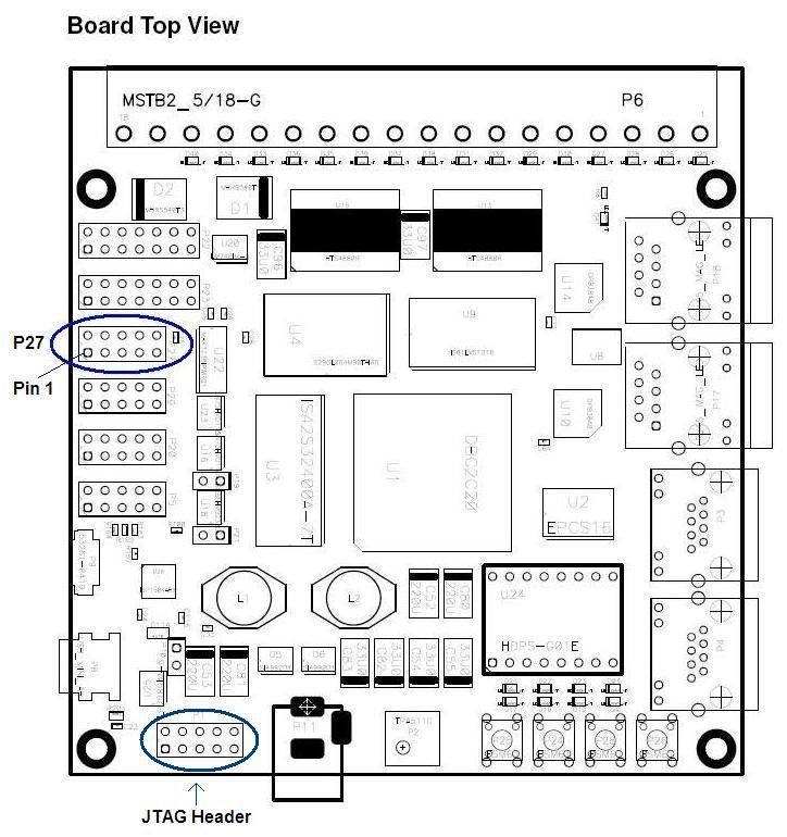
The RS-232 interface uses a null-modem cable that connects the RS-232 header
(P27 – see Figure 1 on page 10) on the DBC2C20 development board to a male D-
SUB9 connector for the RS-232 socket on the FT 3120 or PL 3120 EVB. This
cable is not included with the ShortStack 2 Nios II Example Port.
ShortStack 2 Nios II Example Port User’s Guide 9Figure 1. RS-232 Header (P27) on the DBC2C20 Development Board
To define the null-modem RS-232 interface, use the pin connections listed in
Table 5. Keep the total cable length to a maximum of 24 inches (0.6 meters).
Table 5. RS-232 Header to D-SUB9 Connector Pin Connections
P27 Header Pin D-SUB9 Connector Pin Smart Transceiver Signal
1 NC N/A
2 4 _HRDY
3 3 RXD
10 Overview of the Hardware Environment for the Nios II ProcessorP27 Header Pin D-SUB9 Connector Pin Smart Transceiver Signal
4 8 _CTS
5 2 TXD
6 7 _RTS
7 NC N/A
8 NC N/A
9 5 GND
10 N/A N/A
The Nios II processor communicates with the ShortStack Micro Server through
the SCI interface at a 38 400 bit rate. You can change the communications
interface through compilation-time configuration, as described in
Communications Configuration Options on page 20.
To set the required bit rate for the SCI interface on an FT 3120 EVB or a PL
3120 EVB, set the jumpers for the RS-232 Enable (JP201) and ShortStack Enable
(JP203 and JP204) headers, as shown in Table 6. See the Mini EVK Hardware
Guide for more information about these jumpers.
Recommendation: For both the FT 3120 and PL 3120 EVB, disconnect any
peripheral I/O from the I/O Connector header (P201), such as the MiniGizmo
board, when using these boards in ShortStack mode with an RS-232 connection.
Table 6. Jumper Settings for 3120 EVB Evaluation Boards
Function Evaluation Board Jumper Setting
IO10
IO8
IO4
IO1
FT 3120
JP201
RS-232 Enable
IO8
IO4
PL 3120
IO1
JP201
ShortStack 2 Nios II Example Port User’s Guide 11Function Evaluation Board Jumper Setting
FT 3120
JP203
ShortStack Enable
IO5
IO6
PL 3120
12 Overview of the Hardware Environment for the Nios II Processor3
Developing ShortStack
Applications for the Nios II
Processor
This chapter describes software development tools for the Nios II
processor, and tools for loading and debugging your ShortStack
application.
ShortStack 2 Nios II Example Port User’s Guide 13General Description of the Supported Software
and Tools
The ShortStack 2 Nios II Example Port requires development tools for both
hardware design and software design.
For hardware design, the example requires development tools for FPGA soft
processor design, a system-on-chip design tool, a device programmer to load the
compiled hardware design into the Cyclone II FPGA, and optionally, simulation
tools, a logic analyzer, a timing analyzer, and a chip planner.
For software design, it requires a C compiler, with its associated development
environment, a device programmer to load the compiled program into the Nios II
processor, and optionally an in-circuit debugger to debug and verify the program.
The example also requires that you load the appropriate ShortStack Micro Server
firmware image into the FT Smart Transceiver or PL Smart Transceiver.
The rest of this chapter describes the tools required for development of the
example application.
Software Development Tools for the Nios II
Processor
To develop your ShortStack application for a Nios II processor, you can use any
tools that support the Nios II family of embedded processors. However, this
document describes only the Altera Complete Design Suite, as listed in Table 7.
The example applications were built with the Altera Complete Design Suite,
Version 6.1. You can obtain the Altera Complete Design Suite on DVD-ROM
from Altera Corporation, or you can download the Web Edition of the tools from
https://www.altera.com/support/software/download/nios2/dnl-nios2.jsp.
Table 7. Altera Complete Design Suite
Quartus II Design Software for Windows
The Quartus II design software provides a suite of tools for system-level design,
embedded software programming, FPGA and CPLD design, synthesis, place-and-
route, verification, and device programming. Quartus II software supports all of
Altera's current device families.
The Quartus II Web Edition is a subset of the Quartus II design software that
provides support for selected Altera processors.
Both the Quartus II design software and the Quartus II Web Edition include the
SOPC Builder tool, which is an automated system development tool that
dramatically simplifies the task of creating high-performance system-on-a-
programmable-chip (SOPC) designs.
14 Developing ShortStack Applications for the Nios II ProcessorModelSim®-Altera VHDL & Verilog HDL Simulation Tool
The ModelSim-Altera software is an Altera-specific version of the Model
Technology™ ModelSim simulation software, which supports behavioral
simulation and testbenches for VHDL or Verilog hardware description languages
(HDLs). The ModelSim-Altera software is included with Altera software
subscriptions.
MegaCore IP Library
The MegaCore IP library includes some of Altera’s most popular intellectual
property (IP) cores, including a finite impulse response (FIR) compiler, a
numerically controlled oscillator (NCO) compiler, a fast Fourier transform (FFT)
compiler, several DDR SDRAM controllers, a QDRII SDRAM controller, an
RLDRAM II controller, and a lightweight serial interconnect protocol. The
MegaCore IP library is included with Altera software subscriptions.
Nios II Embedded Design Suite
The Nios II integrated development environment (IDE) is a graphical user
interface (GUI) within which you can accomplish all Nios II embedded processor
software development tasks, including editing, building, managing, and
debugging embedded software programs. The Nios II IDE is included with Altera
software subscriptions.
For more information about installing the Altera Complete Design Suite, see
Quartus II Installation & Licensing for Windows, available from the Quartus II
Development Software Version 6.1 Literature page at
www.altera.com/literature/lit-qts.jsp.
Loading Your Application into the Nios II
Processor
To load your hardware design and software application, plus the ShortStack API
and serial driver, into the Nios II processor, you can use a device programmer,
such as the Altera USB-Blaster download cable, as described in Table 8.
Table 8. Device Programmer for the Nios II Processor
Altera USB-Blaster Download Cable
The USB-Blaster download cable interfaces to a standard PC USB port. This
cable drives configuration or programming data from the PC to the device. For
more information about the USB-Blaster, see the USB-Blaster Download Cable
User Guide.
The Windows driver for the USB-Blaster is in the [Altera]\quartus\drivers\usb-
blaster directory, where [Altera] is the directory in which you installed the Altera
tool chain, usually C:\altera\61.
ShortStack 2 Nios II Example Port User’s Guide 15To set up the programming hardware in the Quartus II software:
1. Start the Quartus II software.
2. Select Tools → Programmer to open the Chain Description File (*.cdf) for
the project.
3. Click Hardware Setup to open the Hardware Setup window.
4. If you have already installed the Windows drivers for the USB-Blaster, it
should appear in the Available hardware items area of the Hardware
Setup window.
5. If the programming hardware that you want to use does not appear in the
Available hardware items area of the Hardware Setup window, click the
Add Hardware button to open the Add Hardware window.
a. Select the appropriate programming cable or programming
hardware from the Hardware Type dropdown list box.
b. Select the appropriate port and baud rate, if necessary.
c. Click OK.
6. Select the programming hardware that you want to use from the
Available hardware items dropdown list box.
7. Click Close to close the Hardware Setup window.
8. Select JTAG from the Mode dropdown list box.
9. Select File → Close to close the Chain Description File.
You can save the Chain Description File (*.cdf) for use with other projects.
Preparing the ShortStack Micro Server
You can load the ShortStack firmware into the non-volatile memory of the FT
3120 Smart Transceiver or the PL 3120 Smart Transceiver using either ex-circuit
programming or in-circuit programming.
Preparing an FT 3120 Smart Transceiver
To load the ShortStack firmware using ex-circuit programming:
• Use either an Echelon or third-party 3120 Programmer to load the
[ShortStack]\Firmware\Images\SS_3120E4_20000KHz.NEI file into the
non-volatile memory
• Use a PROM programmer to load the
[ShortStack]\Firmware\Images\SS_3120E4_20000KHz.NFI file into the
non-volatile memory
where [ShortStack] is the directory where you installed the ShortStack 2
software, usually C:\LonWorks\ShortStack.
To load the ShortStack firmware using in-circuit programming, you can use a
network management tool, such as the LonMaker tool. The device interface (XIF)
file for the project is
[NiosExample]\software\Application_FT\lon\wizard\Sample_Node.xif.
16 Developing ShortStack Applications for the Nios II ProcessorYou can also use the NodeLoad utility to load the SS_3120E4_20000KHz.NEI file
into the FT 3120 Smart Transceiver non-volatile memory over a LONWORKS
network. To use the LonMaker tool or the NodeLoad utility, you need a
LONWORKS network interface, such as a U10 USB Network Interface or a
PCLTA-21 PCI Network Interface.
To load an application image (NEI) file over a LONWORKS network interface
named “LON1”, allowing 20 seconds to press the service pin on the destination
device, and specifying that the utility skip final reset after the download (to
prevent NodeLoad error code 7, state failure), use the following command:
nodeload –Dlon1 –W20 –F –Lss_3120e4_20000khz.nei
The Nodeload utility is available for free download from the LonWorks
Downloads page, www.echelon.com/downloads, in the Development Tools
category.
See the ShortStack User’s Guide and the NodeLoad Utility User’s Guide for more
information about loading the ShortStack Micro Server firmware images.
Preparing a PL 3120 Smart Transceiver
To load the ShortStack firmware using ex-circuit programming:
• Use either an Echelon or third-party 3120 Programmer to load the
[ShortStack]\Firmware\Images\SS_PL3120E4_10000KHz.NEI file into
the non-volatile memory
• Use a PROM programmer to load the
[ShortStack]\Firmware\Images\SS_PL3120E4_10000KHz.NFI file into
the non-volatile memory
where [ShortStack] is the directory where you installed the ShortStack 2
software, usually C:\LonWorks\ShortStack.
To load the ShortStack firmware using in-circuit programming, you can use a
network management tool, such as the LonMaker tool. The device interface (XIF)
file for the project is
[NiosExample]\software\Application_PL\lon\wizard\Sample_Node.xif.
You can also use the NodeLoad utility to load the SS_PL3120E4_10000KHz.NEI
file into the PL 3120 Smart Transceiver non-volatile memory over a LONWORKS
network. To use the LonMaker tool or the NodeLoad utility, you need a
LONWORKS network interface, such as a U20 USB Network Interface or a
PCLTA-21 PCI Network Interface.
To load an application image (NEI) file over a LONWORKS network interface
named “LON1”, allowing 20 seconds to press the service pin on the destination
device, and specifying that the utility skip final reset after the download (to
prevent NodeLoad error code 7, state failure), use the following command:
nodeload –Dlon1 –W20 –F –Lss_pl3120e4_10000khz.nei
The Nodeload utility is available for free download from the LonWorks
Downloads page, www.echelon.com/downloads, in the Development Tools
category.
See the ShortStack User’s Guide and the NodeLoad Utility User’s Guide for more
information about loading the ShortStack Micro Server firmware images.
ShortStack 2 Nios II Example Port User’s Guide 17Debugging Your Application
To debug your application, either the hardware design or the software, you can
use the debug tools supplied with the Quartus II software and the Nios II EDS
IDE, along with the USB-Blaster download cable described in Loading Your
Application into the Nios II Processor on page 15.
18 Developing ShortStack Applications for the Nios II Processor4
Developing the ShortStack Driver
This chapter describes the communications configuration
options for the ShortStack application and the ShortStack
serial driver implementation.
ShortStack 2 Nios II Example Port User’s Guide 19Communications Configuration Options
You can set the serial interface type and the interface bit rate for the example
application.
Setting the Serial Interface Type
The ShortStack 2 Nios II Example Port uses the SCI asynchronous interface, and
does not include an SPI driver. If you want to use the SPI synchronous interface
for communications between the Nios II processor and the ShortStack Micro
Server, you must:
• Modify the Nios II hardware design to add the appropriate I/O lines and
I/O modules
• Implement a lower-layer SPI serial driver for the ShortStack Micro
Server
• Comment-out the SCI definition in the lonsystem.h file:
[NiosExample]\software\Application_FT\lon\driver\lonsystem.h
or
[NiosExample]\software\Application_PL\lon\driver\lonsystem.h
Setting the Interface Bit Rate
The interface bit rate for the example application is defined in the Nios II
processor design. If you want to change the application bit rate:
• Modify the hardware design for the Nios II processor
• Modify the application’s source code to specify the SS_BAUD_RATE
• Set the ShortStack Enable jumpers (JP203 and JP204) on the FT 3120 or
PL 3120 EVB to match the specified bit rate
To modify the interface bit rate within the hardware design:
1. Start the Quartus II software
2. Select File → Open Project to display the Open Project window.
3. In the Open Project window, select the dbc2c20_standard_design.qpf
hardware project file from the [NiosExample] directory, and click Open to
add the project file to the Project Navigator.
4. Double-click the dbc2c20_standard_design in the Project Navigator to
open the Block Design File for the project.
5. Within the Block Design File pane, double-click the nios_cpu block to
open the Altera SOPC Builder window.
6. From the System Contents pane of the SOPC Builder window, right-click
the ShortStack_UART module and select Edit to modify the properties for
the module.
20 Developing the ShortStack Driver7. From the Configuration tab of the Avalon UART – ShortStack_UART
dialog, select the desired bit rate from the Baud Rate (bps) dropdown list
box. Click Finish to close the dialog.
After you modify the bit rate in the hardware design, you must rebuild the
design, as described in Building the Hardware Image on page 32.
To modify the interface bit rate within the application source code, add the
following statement to the lonsystem.h file:
#define SS_BAUD_RATE 0
The values for the SS_BAUD_RATE literal are defined in a set of comments in
the lonsystem.h file. A value of 0 represents a bit rate of 38 400 bps for the SCI
interface.
The selected serial interface type and interface bit rate must match the
configuration of the ShortStack Micro Server to avoid communications problems.
See the ShortStack User’s Guide for more information about setting and
determining the Micro Server interface bit rate. See the Mini EVK Hardware
Guide for more information about setting the ShortStack Enable jumpers.
Serial Driver API
The example serial drivers for the Nios II processor implement two interface
layers:
• An upper-layer interface to the ShortStack API
• A lower-layer interface to the hardware
The source files for the serial-driver implementations are in one of the following
directories, depending on which application you are working with:
• [NiosExample]\software\Application_FT\lon\driver
• [NiosExample]\software\Application_PL\lon\driver
You can use the files in these directories as templates for developing ShortStack
serial drivers for any microcontroller or microprocessor. The SCI driver supports
the interface functions that the ShortStack API requires. The example
application does not include an SPI driver.
The upper-layer driver interface is implemented in the ldvintfc.c file. The lower-
layer driver interface is implemented in the ldvsci.c and hndshk.c files.
The two layers exchange data through a set of four queues. These queues are
implemented in the ldvqueue.c file. The four queues include:
• Outgoing queue (QOutgoing) – contains outgoing messages. The
messages in this queue are sent to the lower-layer driver to send
downlink.
• Free outgoing queue (QFreeOut) – a free buffer pool for outgoing
messages.
• Incoming queue (QIncoming) – contains incoming messages. The
messages in this queue are received by the lower-layer driver, passed to
the upper-layer driver, which in turn passes them to the application.
• Free incoming queue (QFreeIn) – a free buffer pool for incoming
messages.
ShortStack 2 Nios II Example Port User’s Guide 21These queues are accessible from both the upper-layer driver and lower-layer
driver interfaces. The critical data access synchronization is ensured by
disabling and enabling interrupts while accessing the queues.
Figure 2 shows the interaction between the serial driver layers and the queues
for an incoming message:
1. A message arrives from the ShortStack Micro Server
2. The lower-layer driver interface dequeues a buffer from the free incoming
queue
3. The lower-layer driver interface fills the buffer with the received message
and enqueues it to the incoming queue
4. When the host application reads a message, the upper-layer driver
interface dequeues a buffer from the incoming queue
5. The upper-layer driver interface relays the message to the host
application
6. After the host application is done with the message, the upper-layer
driver interface returns the buffer to the free incoming queue
Figure 2. Processing for an Incoming Message
Figure 3 on page 23 shows the interaction between the serial driver interface
layers and the queues for an outgoing message:
1. When the host application needs to send a message, it calls the upper-
layer driver interface
2. The upper-layer driver interface allocates a buffer from the free outgoing
queue
3. After the host application constructs the message, the upper-layer driver
interface enqueues the buffer in the outgoing queue
4. When the lower-layer driver interface is ready to send a message, it frees
a buffer from the outgoing queue
5. The lower-layer driver interface transmits the message to the ShortStack
Micro Server
22 Developing the ShortStack Driver6. The lower-layer driver interface returns the buffer to the outgoing free
queue after transmission is completed
Figure 3. Processing for an Outgoing Message
Upper-Layer Serial Driver Implementation
The ldvintfc.c file implements the following functions:
• ldv_init(): Initializes the queues and the serial driver.
• ldv_get_msg(): Determines if there are messages waiting in the receive
buffer by dequeuing an element from the incoming queue.
• ldv_release_msg(): Releases a receive buffer by enqueuing it to the free
incoming queue.
• ldv_allocate_msg(): Determines if there is an available transmit buffer by
dequeuing an element from the free outgoing queue.
• ldv_put_msg(): Sends a message downlink and frees the transmit buffer
by enqueuing it to the outgoing queue.
• ldv_put_msg_init(): Calls the SysPutMsgInit() function to send messages
downlink that are longer than a single transmit buffer.
• ldv_flush_msgs(): Calls the SysFlushTxBuf() function to cause the driver
to transmit messages that are waiting in transmit buffers.
Lower-Layer SCI Serial Driver Implementation
The ldvsci.c file implements the following functions:
• SysInit(): Initializes the lower-layer serial driver.
• SysEnableInterrupts(): Enables all interrupts for the ShortStack UART.
ShortStack 2 Nios II Example Port User’s Guide 23• SysDisableInterrupts(): Disables all interrupts for the ShortStack UART.
• EnableCTSIRQ(): Enables the CTS handshake interrupt handler.
• DisableCTSIRQ(): Disables the CTS handshake interrupt handler.
• EnableRxIRQ(): Enables the receive indication interrupt handler.
• DisableRxIRQ(): Disables the receive indication interrupt handler.
• EnableTxIRQ(): Enables the transmit-ready indication interrupt
handler.
• DisableTxIRQ(): Disables the transmit-ready indication interrupt
handler.
• SysResetSCI(): Performs a partial reset of the Nios II processor by
resetting the SCI interface. It also informs the ShortStack Micro Server
that the host is not ready.
• CTSInt(): The CTS handshake interrupt service routine. Because the
CTS line is polled for the Nios II example application, this function is
obsolete.
• UARTInt(): The UART interrupt service routine. Because the Nios II
UART shares a single interrupt service routine for both RX and TX
interrupts, this function determines the reason for the interrupt and calls
the appropriate service function.
• WaitForCTSLow(): Waits until the CTS line is low or until a timeout
occurs.
• WaitForCTSHigh(): Waits until the CTS line is high or until a timeout
occurs.
• SysPutMsgInit(): Sends messages downlink that are longer than a single
transmit buffer.
• SysFlushTxBuf(): Flushes the lower-layer serial driver’s transmit
buffers.
• SysTxMsgCompleted(): Returns a buffer to the free outgoing buffer pool
and resets the serial driver’s status after successful message
transmission.
• RxIntService(): The SCI interrupt handler for receiving messages.
• TxIntService(): The SCI interrupt handler for transmitting messages.
• SCIERRIntService(): The SCI interrupt handler for error conditions.
This function resets the SCI interface.
• TBInt(): The timebase interrupt handler. This function is executed every
millisecond, and ensures that the driver is running and that the 3120
EVB’s RS-232 UART remains active.
The hndshk.c file implements the following functions to access the reset and
handshake lines:
• AssertRTS()
• DeassertRTS()
• AssertHRDY()
24 Developing the ShortStack Driver• DeassertHRDY()
• ResetTransceiver()
• InitHandshake()
• CheckCTS()
ShortStack 2 Nios II Example Port User’s Guide 255
Exploring the Simple Voltage
Amplifier Example Application
This chapter describes the simple voltage amplifier example
application, including the application’s design, main() and
callback functions, and Neuron C model file. This chapter
also describes how to build and load the application images
and run the example application.
ShortStack 2 Nios II Example Port User’s Guide 27Overview
The simple voltage amplifier example application is a very simple application
that simulates a voltage amplifier device. This device receives an input voltage
value, multiplies the value by 2, and returns the new output value. Figure 4
shows the functional blocks for the application.
Figure 4. Voltage Amplifier Functionality
The Controller functional block defines the voltage amplification. The Node
Object functional block defines an interface for device interoperability. However,
because the Controller functional block is deprecated, the example is not
compliant with current LONMARK® interoperability guidelines, which are
available at www.lonmark.org.
Design
The design of the example application is very simple. It includes a single C
source file (main.c), the ShortStack API files generated by the ShortStack
Wizard, and the ShortStack Serial Driver.
The following sections describe the application’s main() function, callback
functions, and Neuron C model file.
Main Function
The main() function performs the following tasks:
1. Calls the lonInit() ShortStack API function to initialize the ShortStack
API, the ShortStack serial driver, and the ShortStack Micro Server.
2. Runs an infinite loop to repeatedly call the lonEventHandler() API
function to handle LONWORKS events.
Although the main() function for this application is an example, you can use the
same basic algorithmic approach for a production-level application.
The main.c file in both of the following directories contains the main() function,
which is shown below:
• [NiosExample]\software\Application_FT
• [NiosExample]\software\Application_PL
/*
* Main Function
*/
int main (void)
{
// Initialize your host-side hardware here, TBD
28 Exploring the Simple Voltage Amplifier Example Application// Initialize your host-side software here, TBD
// Initialize ShortStack API, serial driver, and
// ShortStack Micro Server
printf ("Initializing LON...");
lonInit();
printf ("done.\n");
printf ("You can use LonMaker to test your device
now.\n");
// Handle messages in a loop
for (;;)
{
/* Handle LonWorks events.
* The corresponding callbacks are defined in
* lon/lonapp.c
*/
lonEventHandler();
// Process your application, TBD
// Sleep
usleep (10000);
}
return (0); /* Pro forma */
}
Callback Functions
To signal to the main application the occurrence of certain types of events, the
ShortStack API calls specific callback functions. For the voltage amplifier
example application, only one of the API’s callback functions has been
implemented to provide application-specific behavior.
The lonNvUpdateOccurred() function, which is called when the host receives a
network-variable update, contains a C switch statement, which performs the
following tasks:
• Sets the network variables for the Node Object functional block.
• Sets the output network variable for the Controller functional block to
double the value of the input network variable, and propagates the
output network-variable to the network.
The two network variables are defined in the Neuron C model file, which is
described in Neuron C Model File on page 30.
The lonapp.c file in both of the following directories contains the
lonNvUpdateOccurred() function, which is shown below:
• [NiosExample]\software\Application_FT\lon\api
• [NiosExample]\software\Application_PL\lon\api
ShortStack 2 Nios II Example Port User’s Guide 29void lonNvUpdateOccurred(const Byte nvIndex, const
RcvAddrDtl* const pNvInAddr)
{
switch (nvIndex)
{
case NVIDX_nviRequest:
nvoStatus.object_id = nviRequest.object_id;
nvoStatus.invalid_id = 1;
nvoStatus.invalid_request = 1;
break;
case NVIDX_nviVolt:
nvoVolt = NET_SWAB_WORD(2*NET_SWAB_WORD(nviVolt));
if (lonPropagateNv(NVIDX_nvoVolt) != API_NO_ERROR)
{
// Handle error here, if desired.
}
break;
default:
break;
}
}
Neuron C Model File
The Neuron C model file, Sample_Node.nc, defines the LONWORKS interface for
the example ShortStack device. This file is in the following directories:
• [NiosExample]\software\Application_FT\lon\wizard
• [NiosExample]\software\Application_PL\lon\wizard
The model defines two functional blocks, NodeObject and Volt_Amplifier. The
Volt_Amplifier functional block includes two network variables, nviVolt and
nvoVolt. The functionality for these network variables is implemented in the
lonNvUpdateOccurred() callback function described in Callback Functions on
page 29.
The Neuron C model file is shown below.
#pragma enable_sd_nv_names
#pragma set_node_sd_string "A simple voltage amplifier"
// Node object
network input SNVT_obj_request nviRequest;
network output SNVT_obj_status nvoStatus;
fblock SFPTnodeObject {
nviRequest implements nviRequest;
nvoStatus implements nvoStatus;
} NodeObject;
// Voltage-current converter
30 Exploring the Simple Voltage Amplifier Example Applicationnetwork input SNVT_volt nviVolt;
network output SNVT_volt nvoVolt;
fblock SFPTcontroller {
nviVolt implements nviValue;
nvoVolt implements nvoValue;
} Volt_Amplifier;
Using the Sample_Node.nc file as the model file, the ShortStack Wizard
generated the following files: filedir.h, LonDev.c, LonDev.h, NvTypes.h and
platform.h. For more information about creating and using a Neuron C model
file, see the ShortStack User’s Guide.
To change the LONWORKS interface and functionality of the example application,
perform the following steps:
1. Define the interface in the Sample_Node.nc Neuron C model file.
2. Run the ShortStack Wizard and modify its output as described in
Modifying the Output of the ShortStack Wizard.
3. Make appropriate changes to the callback functions in the lonapp.c file.
4. Rebuild the project.
5. Load the generated XIF file into the Smart Transceiver.
6. Load the new executable file into the Nios II processor.
Modifying the Output of the ShortStack Wizard
After you run the ShortStack Wizard to generate the filedir.h, LonDev.c,
LonDev.h, NvTypes.h and platform.h files, you must make the following manual
changes:
1. Delete the generated platform.h file from the directory in which you are
running the ShortStack Wizard:
• [NiosExample]\software\Application_FT\lon\wizard
• [NiosExample]\software\Application_PL\lon\wizard
2. Copy the platform.h file that was installed with the ShortStack 2 Nios II
Example Port to the appropriate [NiosExample] directory, as listed in
Table 9.
Table 9. Copying platform.h
From To
[ShortStack]\Examples\NiosII\ [NiosExample]\software\Application_FT
nios_II_echelon_ShortStack_EVB_ \lon\wizard\platform.h
application\software\Application_FT\lon
\wizard\platform.h
[ShortStack]\Examples\NiosII\ [NiosExample]\software\Application_PL
nios_II_echelon_ShortStack_EVB_ \lon\wizard\platform.h
application\software\Application_PL\lon
\wizard\platform.h
ShortStack 2 Nios II Example Port User’s Guide 31You can also read