DE Series for Video Surveillance Best Practices Guide
←
→
Page content transcription
If your browser does not render page correctly, please read the page content below
DE Series for Video Surveillance Best Practices
Guide
Deploy and Configure DE Series for Video Surveillance

Abstract
Video surveillance solutions using Lenovo® DE Series storage offer a highly scalable repository for video recording.
This guide offers best practices for deploying DE Series arrays into video surveillance environments.
First edition (July 2020)
© Copyright Lenovo 2020.
LIMITED AND RESTRICTED RIGHTS NOTICE: If data or software is delivered pursuant to a General Services
Administration (GSA) contract, use, reproduction, or disclosure is subject to restrictions set forth in Contract
No. GS-35F-05925
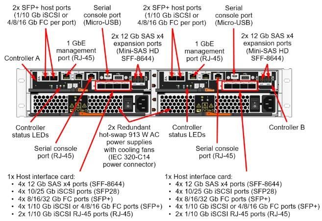
TABLE OF CONTENTS
1      Introduction ............................................................................................................................................. 1
       1.1     Publication Scope .............................................................................................................................................1
       1.2     Audience ...........................................................................................................................................................1
       1.3     Why Should You Use DE Series for Video Surveillance? .................................................................................1
2      Reference Architecture .......................................................................................................................... 2
3      VSS Storage Sizing and Selection Guide ............................................................................................. 4
       3.1     Lenovo DE Series Storage Sizing .....................................................................................................................4
       3.2     Lenovo DE Series Virtualization Sizing .............................................................................................................8
4      DE Series Storage Considerations ....................................................................................................... 9
       4.1     Workload ...........................................................................................................................................................9
       4.2     Dynamic Disk Pools (DDP) Feature ..................................................................................................................9
       4.3     RAID Levels ....................................................................................................................................................10
       4.4     I/O Characteristics ...........................................................................................................................................10
       4.5     High Availability ...............................................................................................................................................11
5      Lenovo DE Series Storage Provisioning ............................................................................................ 11
6      Server Considerations .......................................................................................................................... 20
       6.1     Multipath I/O Device-Specific Module Installation ...........................................................................................21
       6.2     DE Series LUN Discovery and Preparation .....................................................................................................21
7      Networking Considerations ................................................................................................................. 22
       7.1     Traffic Management ........................................................................................................................................25
Where to Find Additional Information ........................................................................................................ 26
Contacting Support ...................................................................................................................................... 26
Notices ........................................................................................................................................................... 27
Trademarks .................................................................................................................................................... 28

 LIST OF TABLES
 Table 1) VSS components ..............................................................................................................................................3
 Table 2) Lenovo VSS sizing tool parameters..................................................................................................................5
 Table 3) DDP pool usable capacity versus number of drives .........................................................................................9
 Table 4) Supported controller and expansion enclosure combinations......................................................................... 10
 Table 5) Virtual machine common five-drive RAID 6 SSD usable capacities ............................................................... 10
 Table 6) DDP pool usable capacity for common virtualization ...................................................................................... 11
 Table 7) Recording server characteristics that Lenovo recommends ........................................................................... 22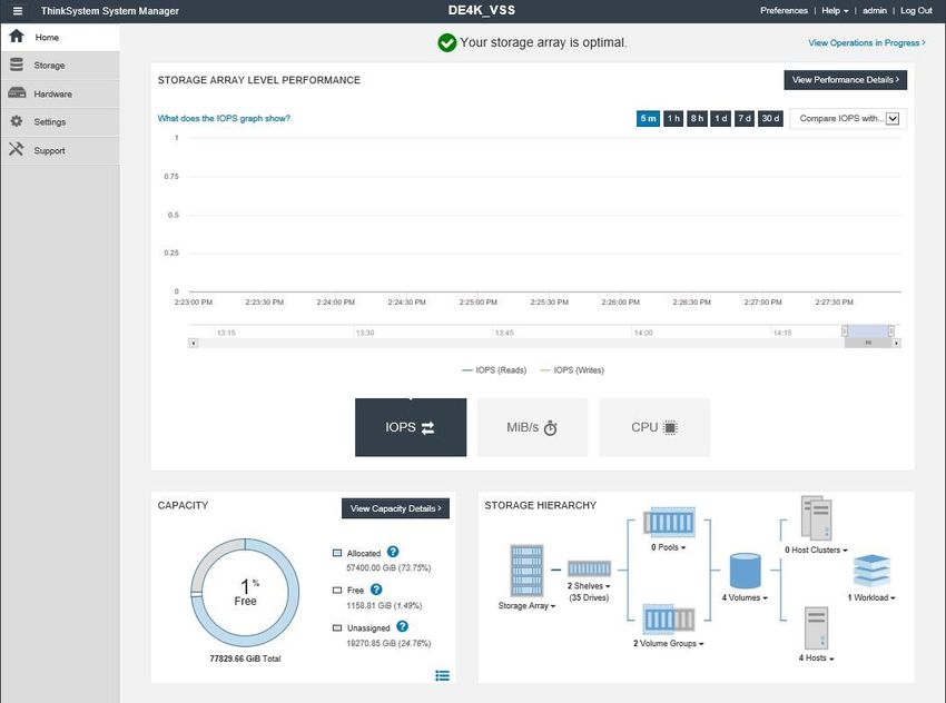
LIST OF FIGURES
Figure 1) Video surveillance architecture with VMS and Lenovo DE Series arrays. .......................................................3
Figure 2) ThinkSystem System Manager home screen. ...............................................................................................12
Figure 3) Pools & Volume Groups tile. .........................................................................................................................12
Figure 4) Create a DDP pool. .......................................................................................................................................13
Figure 5) Name the pool and select drives for the pool. ...............................................................................................13
Figure 6) Create a volume. ...........................................................................................................................................14
Figure 7) Create a volume (continued). ........................................................................................................................15
Figure 8) Example of final volume configuration. ..........................................................................................................16
Figure 9) iSCSI settings................................................................................................................................................16
Figure 10) iSCSI settings (continued). ..........................................................................................................................17
Figure 11) Create a host...............................................................................................................................................17
Figure 12) Create a host (continued). ...........................................................................................................................18
Figure 13) Host definitions............................................................................................................................................18
Figure 14) Assign volumes to the host. ........................................................................................................................19
Figure 15) Select volumes to assign. ...........................................................................................................................19
Figure 16) Host with assigned volumes. .......................................................................................................................20
Figure 17) Lenovo ThinkSystem Storage Manager installation. ...................................................................................21
Figure 18) Back view of the DE2000 controller. ...........................................................................................................23
Figure 19) Back view of the DE4000 controller. ...........................................................................................................24
Figure 20) Back view of the DE6000 controller. ...........................................................................................................25
1 Introduction
Lenovo DE Series storage arrays provide performance, efficiency, reliability, and enterprise-class support
for large-scale video surveillance deployments.
All video surveillance management software shares the common feature of recording live video feeds to
storage for subsequent replay. This replay helps with forensic analysis or with investigation of people or
events that were within the field of view of a single camera or a group of cameras. These video feeds,
generated by hundreds or thousands of cameras, are typically configured to record continuously with
retention periods in the range of months to years.
1.1 Publication Scope
This document provides architecture and deployment guidelines for video surveillance solutions to those
who sell, design, or implement such solutions based on Lenovo DE Series storage. It describes the
comprehensive functional components that are required to build a video surveillance solution based on
Lenovo DE Series storage that can reliably record video and archive video from recording servers. This
document identifies the major components and features of a video surveillance system.
1.2 Audience
This publication is intended for IT professionals who are responsible for integrating Lenovo DE Series
storage systems into existing video surveillance deployments or who design and implement new video
surveillance deployments. This audience includes physical-security integrators, video surveillance
management software engineers, network and storage system engineers, and architects.
The content in this report is presented with the expectation that these professionals can use this
information, combined with their experience and supporting documents, to build an efficient, scalable, and
highly available system.
Targeted Deployments
The targeted deployments for this introduction are large (200 cameras or more) video surveillance
installations with significant storage capacity requirements due to retention periods of at least 30 days or
the use of HD/megapixel-resolution cameras.
1.3 Why Should You Use DE Series for Video Surveillance?
The DE Series architecture supports block-based protocols and can process real-time video applications
with high reliability, high performance, and high availability. For these reasons, DE Series is the preferred
choice for video surveillance solutions that are designed to use Lenovo storage.
Solution Benefits
Lenovo DE Series provides the following benefits for large-scale video surveillance deployments:
Easy management and monitoring. The included Lenovo ThinkSystem System Manager
software provides a graphical representation of the DE Series storage, with an easy-to-use
interface.
Easy provisioning. ThinkSystem System Manager software performs all management tasks for
the array without taking the array offline.
High availability. Dual controllers enable nondisruptive controller firmware upgrades, host multipath
support, and dual paths to expansion shelves.
High performance. DE Series controllers offer an excellent price-to-performance ratio.
Scalability. With just a couple mouse clicks, you can easily add or expand capacity when you add
more drives to your system. The DE6000H supports up to 7.68PB of raw capacity
1 DE Series for Video Surveillance Best Practices Guide © 2020 Lenovo. All Rights Reserved.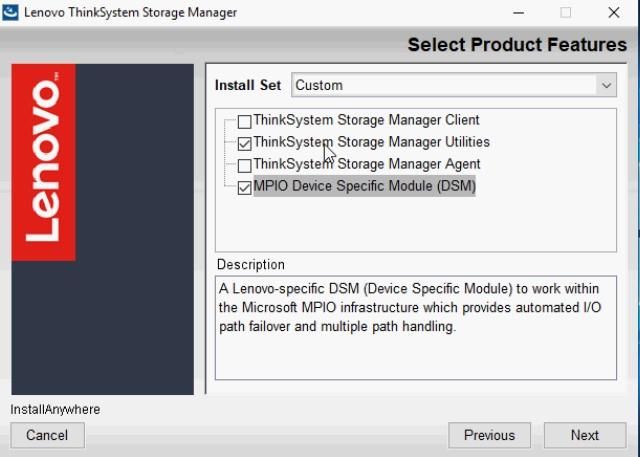
(using 16TB drives) in an efficient footprint. The entry-level DE4000H supports up to 3.1PB of raw
capacity (using 16TB drives) and DE2000H supports up to 1.54PB of raw capacity (using 16Tb
drives).
Drive health monitoring. DE Series systems provide proactive monitoring, background repair,
and extensive diagnostic features for drives.
T10 Standard data integrity and media scan. This scan detects and corrects data integrity issues
that the recording server receives or that are caused by hardware failures on the drives.
Data protection. DE Series systems support RAID levels 0, 1, 10, 3, 5, and 6 for volume groups
and for Dynamic Disk Pools (DDP).
Certified interoperability. DE Series systems are certified to be interoperable with multiple
video management software (VMS) providers.
2 Reference Architecture
A typical video surveillance solution (VSS) with Lenovo DE Series storage arrays consists of the
following main components:
IP cameras
Camera network
Management server or servers
Recording server or servers
Failover server or servers (optional)
Viewing client or clients
Storage network
Lenovo DE Series storage array or arrays
Figure 1 shows these components in a standard configuration.
2 DE Series for Video Surveillance Best Practices Guide © 2020 Lenovo. All Rights Reserved.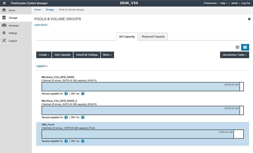
Figure 1) Video surveillance architecture with VMS and Lenovo DE Series arrays.

Table 1 provides a brief explanation of each of these components.

Table 1) VSS components.

 Component                                     Description
 IP cameras                                    Provide audio and video streams for live viewing and for recording for later
                                               playback by using the VMS.

 IP network                                    Enables communication among camera streams and various VMS
                                               components.

 3      DE Series for Video Surveillance Best Practices Guide                               © 2020 Lenovo. All Rights Reserved.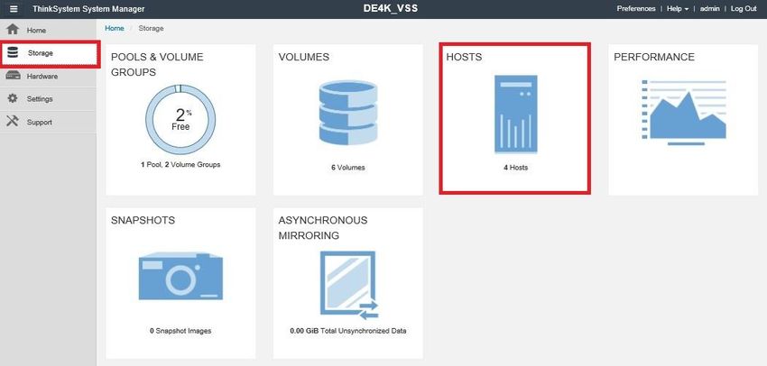
Component Description
Management server Acts as the central point for configuring all the VMS components.
Recording servers Are responsible for recording and playback of audio and video streams as
per the configuration that the management server dictates.
Failover servers Provide redundancy against recording server failures (optional).
Viewing clients Provide live viewing of camera streams or playback of recorded audio and
video by the recording servers.
Storage network Enables communication among the recording and failover servers and the
Lenovo DE Series storage arrays. This network is typically iSCSI, but FC
and SAS protocols are also supported.
Lenovo DE Series storage Provide highly available storage for video and audio files from the
arrays recording and failover servers.
Note: For detailed information about all the supported configurations and additional components, refer
to the specific VMS provider that you are using.
The following sections provide general guidelines on how to size and tune VSS components, especially
the Lenovo DE Series storage arrays, for optimal results. You should use these guidelines along with
the VMS provider recommendations.
3 VSS Storage Sizing and Selection Guide
This section highlights various aspects of the VSS that affect its storage needs, along with an example
estimation and model selection.
System Requirements
The system requirements are specified in a request for proposal (RF) or a quote that is developed by
either the end customer or a physical-security integrator who is in contract with the end customer.
The physical-security integrator must work with the physical-security manager to accurately assess
specific requirements, including:
Number, location, and type of cameras; resolution; frame rate; and so on
Number of recording servers
Number of cameras per recording server
Virtualization requirements
Video management software (VMS) type
Continuous recording or record on motion
Retention period and archiving requirements
Failover design requirements
Note: To verify these requirements, the VMS provider’s sizer should be referenced.
3.1 Lenovo DE Series Storage Sizing
Each recording server has specific storage needs that are based on the number and type of cameras and
the recording parameters that it must support. Contact your salesperson to size VSS storage for your
deployment. Your Lenovo salesperson takes into consideration the inputs shows in Table 2 for each
camera group and estimates the total amount of storage needed for your entire VSS deployment. Your
Lenovo salesperson also has the tools to draw recommendations for the appropriate Lenovo DE series
storage products based on your VSS storage sizing needs.
4 DE Series for Video Surveillance Best Practices Guide © 2020 Lenovo. All Rights Reserved.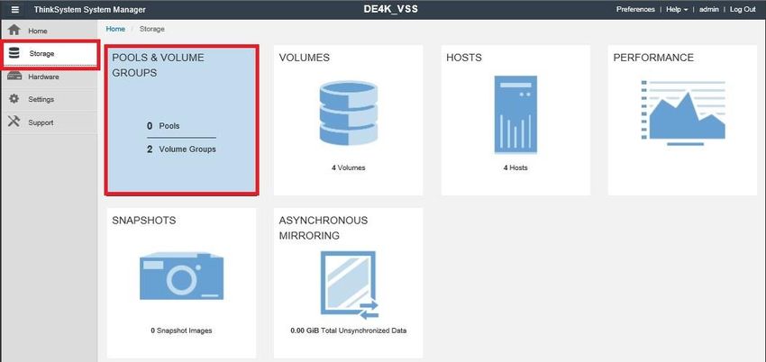
Storage Estimation for Live and Archived Recording
Table 2 lists the parameters that are needed to estimate VSS storage needed:
Table 2) Lenovo VSS sizing tool parameters.
Parameter Description
Camera group/number of cameras VSS site divided into camera groups, with the number of cameras
installed in each group; for example, parking lot, office space.
Camera resolution Average camera resolution of the camera group; for example,
1280x720, 1920x1080.
Compression type Average compression type of the camera group; for example,
H.264-30, H.265-20.
Frames per second (FPS) Average FPS of the camera group; for example, 15, 30
Motion activity The likelihood that motion will occur in the field of view of the
camera group. For example, low (stairway, emergency exit), high
(intersection, subway).
Bit rate Average bit rate of the camera group in Kbps (if known).
Note: This parameter supersedes the resolution, compression type,
FPS, and motion activity parameters.
Recorded hours per day Average hours per day that the camera group will be recording; for
example, 12, 24.
Days to retain Maximum number of days that the video will be saved for the
camera group, either under live recording, archived recording, or
both.
As an example, for a group of cameras with the following parameters, storage needed is shown
below:
Input parameters:
Number of cameras: 25
Resolution: 1920x1080
Compression type: H.264-30
FPS: 20
Motion activity: below average
Recorded hours per day: 24
Days to retain: 30
Storage needed:
Total throughput: 72.63Mbps
Total storage: 23.01TiB
Storage per camera: 0.93TiB
5 DE Series for Video Surveillance Best Practices Guide © 2020 Lenovo. All Rights Reserved.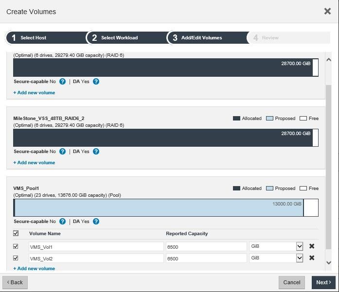
As an example, for a group of cameras with the feed quality information in bitrate, storage
needed is shown below:
Input parameters:
Number of cameras: 50
Bit rate: 2000Kbps
Recorded hours per day: 24
Days to retain: 30
Storage needed:
Total throughput: 172.63Mbps
Total storage: 54.69TiB
Storage per camera: 0.73TiB
Note: In addition to required storage, the throughput estimate also influences the optimal storage model
selection for a VSS. For more details, see the Lenovo DE Series Storage Selection section.
Storage Estimation for Reserved Capacity
When you define the retention period policy, you must consider the amount of reserved capacity. As a
best practice to prevent the “disk full” error condition, each volume that is attached to a recording server
should be maintained at approximately 80% utilization.
By using the storage estimate example, following is the reserved capacity estimate:
Required storage: 192TiB
Reserved storage: (192 x 0.2) = 38TiB
Storage Estimation for the Failover Server Volume
Lenovo recommends that you size the volume for each failover server to retain a minimum of 3 to 5 days
of video from the recording server. To calculate the size of the failover server volume, divide the capacity
of the recording server volume by the site retention period and then multiply by the number of days to
retain during failover.
By using the storage estimate example, following is the failover server volume capacity estimate:
Required storage: 192TiB
Reserved storage: [(192 / 30) x 5] = 32TiB
Sizing for Archiving
Generally speaking, the archiving process copies data from one location to another. Therefore, for every
initial write, you must read and then write the data again. Also, archiving typically runs on a schedule, so it
must be able to archive a day’s worth of data in less than a day. Many users choose to reduce the frame
rate for the video that they archive, which saves some percentage of the initial size of the video.
Depending on the format, it might be linear savings (MJPEG) or marginal savings (H.264). This approach
6 DE Series for Video Surveillance Best Practices Guide © 2020 Lenovo. All Rights Reserved.reduces the amount of bandwidth that is required to archive on the target volume and reduces the
amount of storage capacity that is needed to reserve and to store the video.
As a general rule, you want to ensure that your archiving runs at no less than 1.5x the rate at which the
initial recording is providing new data. For example, if your system ingests 100MBps of video data, it
should be able to archive at 150MBps or more. This rate provides a margin of safety so that your video
can be successfully archived before the drive capacity runs out. If archiving never completes in a timely
manner, the VMS is eventually forced to delete data before the configured data expiration. To avoid
drive contention, Lenovo also recommends that you archive to a different volume on a different DDP
pool instead of archiving to the live recording volume.
Lenovo DE Series Storage Selection
Lenovo offers various DE Series storage models that can match typical VSS price, performance,
capacity and analytics needs. Following are some of the details of these models:
DE2000H 2U12, DE4000H 2U12, DE4000H 4U60, and DE6000H 4U60 are dual-controller hybrid
arrays for capacity needs.
4TB, 8TB, 10TB, 12TB and 16TB NL-SAS HDDs are supported.
DE4000F 2U24 and DE6000F all flash arrays for video analytics needs.
800GB and 1.6TB 3DWD SSDs, and 3.84TB, 7.68TB and 15.36TB 1DWD SSDs are supported.
Traditional RAID volume groups and (RAID 6–based) DDP pools are supported
Note: Section 4, DE Series Storage Considerations, provides the pros and cons of using DDP pools
over traditional RAID volume groups, as well as the optimal volume layout for recording and
failover servers.
Table 3 provides a reference for estimating the number of different capacity drives that are required with
DDP to satisfy specific usable capacity needs. You can use this table to extrapolate the additional
number of drives that you might need.
Table 3) DDP pool usable capacity versus number of drives (Note that 1 TiB = 1.099TB and 1 PiB = 1.125PB).
Number of DDP (4TB) DDP (8TB) DDP (10TB DDP (12TB) DDP (16TB)
Drives w/Encryption)
12 28.62TiB 56.31TiB 70.16TiB 84.2TiB 112.27TiB
24 62.95TiB 123.89TiB 154.34TiB 185.24TiB 247.03TiB
30 80.13TiB 157.67TiB 196.44TiB 235.76TiB 314.35TiB
48 130.08TiB 255.97TiB 318.9TiB 382.74TiB 510.32TiB
60 164.77TiB 324.23TiB 403.94TiB 484.8TiB 646.40TiB
90 248.6TiB 489.19TiB 609.45TiB 731.46TiB 975.28TiB
120 335.32TiB 659.83TiB 822.05TiB 986.62TiB 1.32PiB
180 502.98TiB 989.75TiB 1.2PiB 1.45PiB 1.93PiB
240 673.52TiB 1.29PiB 1.61PiB 1.94PiB 2.58PiB
480 1.33PiB 2.61PiB 3.25PiB 3.90PiB 5.21PiB
7 DE Series for Video Surveillance Best Practices Guide © 2020 Lenovo. All Rights Reserved.Table 4 provides a reference to determine the supported controller and expansion enclosure
combinations that can satisfy specific usable capacity needs in conjunction with Table 3.
Table 4) Supported controller and expansion enclosure combinations.
DE2000H DE4000H DE4000H DE6000H
2U12 2U12 4U60 6U60
Form factor 2U/12 drives 2U/12 drives 4U/60 drives 4U/60 drives
Maximum drives 96 192 192 480
Controller shelf 1 1 1 1
Maximum expansion shelves 3 7 3 7
Total (maximum) number of drive
4 8 4 8
shelves
Maximum raw Capacity 1.50PB 3.07PB 3.07PB 7.68PB
Note: For a comprehensive list of DE product options, go to LSST (the Lenovo storage sizing tool)
or contact a Lenovo storage sales person. LSST takes into account the throughput
requirements of the solution in addition to capacity needs.
3.2 Lenovo DE Series Virtualization Sizing
Virtualization is useful in deployments where resource utilization can be pooled and shared. It enables
your system to provision resources faster and requires fewer physical servers to manage, all in a
simplified interface. Your video surveillance deployment can use virtualization to scale compute,
memory, and storage to meet the demands of many types of expansions. For example, you can increase
retention, increase frame rate, and add cameras seamlessly.
Lenovo DE Series systems are an excellent choice for the storage behind these virtual environments.
DE Series systems give you the option for hybrid storage. With a hybrid approach, virtual machines can
use high-performing SSDs and also satisfy VSS requirements with inexpensive, larger-capacity NL-
SAS HDDs, all within the same storage system.
This section considers sizing requirements for virtualized video surveillance deployments that differ
from bare-metal deployments. Virtualizing Video Management Systems with Lenovo DE Series Storage
provides a comprehensive deployment guide for virtualized video surveillance solutions.
Storage Estimation for Virtualization
Use flash media to meet the latency requirements of common virtual infrastructures such as the ESXi
virtual machine and the VMS application and OS. Because virtual machines are critical for the health of
your overall VSS deployment, Lenovo recommends a RAID 6 dual-drive parity. Lenovo DE Series
storage requires a minimum of five drives when you deploy RAID 6.
Table 5) Virtual machine common five-drive RAID 6 SSD usable capacities (Note that 1 TiB = 1.099TB).
5 x 800GB SSD 5 x 1.6TB SSD 5 X 3.84TB 5 X 7.68TB 5 X 15.36TB
2.17TiB 4.35TiB 10.46TiB 20.94TiB 41.90TiB
Virtual machine storage reduces the total usable capacities for VSS recording by a minimum of five
drives, depending on the capacity that is required for the virtual machines. Table 6 lists usable VSS
capacities for common deployments; these capacities include the reduction for common
virtualization required storage.
8 DE Series for Video Surveillance Best Practices Guide © 2020 Lenovo. All Rights Reserved.Table 6) DDP pool usable capacity for common virtualization (Note that 1 TiB = 1.099TB and 1 PiB = 1.125PB). Number of DDP (4TB) DDP (8TB) DDP (10TB DDP (12TB) DDP (16TB) Drives w/Encryption) 55 150.32TiB 295.79TiB 368.50TiB 442.28TiB 589.71TiB 85 234.14TiB 460.75TiB 574.02TiB 688.93TiB 918.57TiB 115 320.86TiB 631.39TiB 786.62TiB 944.09TiB 1.26PiB 175 488.52TiB 961.31TiB 1.17PiB 1.40PiB 1.87PiB 4 DE Series Storage Considerations Each video recording server requires one or more volumes (LUNs) to be defined to the OS to archive video files. To configure the DE Series storage array, use Lenovo ThinkSystem System Manager to allocate individual drives to a disk pool or to a volume group. The minimum number of drives in a disk pool is 11, but the minimum number of drives for a volume group depends on the RAID level. The maximum number of drives for RAID 5 or RAID 6 is 30. The limit for a disk pool is the total population of drives in the array. During the volume group definition step, you select the RAID level for all drives that are assigned to the volume group. The supported levels of RAID 0, 1, 10, 3, 5, and 6 are for traditional volume groups, and DDP uses RAID 6 stripes that are allocated over 10 of the drives in the pool. Individual volumes (LUNs) are created and mapped to a host after you define the disk pool or volume group. The performance and sizing requirements of your video recording server and your application software determine the number of drives per volume group or per pool and the number of volumes per group or per pool. 4.1 Workload The performance of storage systems is characterized by I/O operations per second (IOPS) and by throughput in megabytes per second. Network performance is measured in packets per second and the throughput is measured in megabits per second. When the storage array is used for small random I/O operations from multiple applications, it is important to optimize IOPS. Also in that use case, network packet-per-second performance is usually measured in small (64-byte) packets. Video surveillance deployments, however, are more concerned with throughput performance than with IOPS. Network video cameras generate large IP packets to the recording servers and write relatively large records to the storage array. Video ingress to the recording servers is over an IP network, and the data rate is typically calculated in megabits per second (Mbps) for IP networks. Therefore, many of the tables in this document list Mbps rather than megabytes per second (MBps). 4.2 Dynamic Disk Pools (DDP) Feature To maintain a consistent level of performance even in the event of drive failure and reconstruction, the Dynamic Disk Pools (DDP) feature is available on DE Series systems. The DDP feature minimizes the performance drop during rebuild, and the rebuild completes more quickly than with a traditional RAID rebuild. Because of the shorter rebuild time with DDP, your exposure to data loss from several drive failures is minimized. With DDP, you can also add capacity incrementally without having to create new volume groups. You can define a single pool that includes all the drives in your system, or you can define multiple pools for your system. A typical deployment has 30 to 60 drives per pool. Because of these factors, Lenovo recommends DDP as the optimal choice for video surveillance. 9 DE Series for Video Surveillance Best Practices Guide © 2020 Lenovo. All Rights Reserved.
4.3     RAID Levels
Although DDP is recommended as the go-to choice for video surveillance deployments, RAID 5, RAID
6, or RAID 10 is commonly deployed in the industry. The Nevada Gaming Commission standards, for
example, specify that the storage array must not lose data if a single component fails. Although RAID 6
and DDP provide better fault tolerance because they can tolerate two simultaneous drive failures, RAID
5 is often deployed instead because it costs less and still adheres to the standards. Also, if a VSS
deployment uses virtualization and the virtual machine storage resides externally, it likely needs a RAID
deployment for an all-flash volume group.
RAID 10 is typically used for optimal read performance when it is combined with SSDs. RAID 5 or RAID 6
is used for optimal write performance. On DE Series systems, you implement RAID 10 by selecting RAID
1 with four or more drives.
Some VMS vendors recommend a combination of RAID 10 and RAID 5 in gaming deployments, where a
high volume of forensic analysis occurs, and during the most recent minutes or hours of video archives.
These designs use RAID 10 for the most recent archive, then, with the tiered storage feature, move video
to a RAID 5 volume group for the duration of the retention period.
This design consideration might not be required in environments that have infrequent forensic analysis or
where the performance level is such that the RAID 5 or RAID 6 volume group provides acceptable read
performance. The education market is one vertical in which archived video is reviewed only if an incident
(for example, vandalism or an altercation between students) warrants analysis of the video.
Note:    When you work with RAID 5 and RAID 10 volume groups, which can handle only one drive
         failure, you should consider allocating hot spares to reduce your risk of data loss if an additional
         drive fails.

4.4     I/O Characteristics
In many deployments, the video surveillance workload is characterized as exceeding a 90% write
workload. In these deployments, video is archived to drive either continuously or based on motion
detection and is not reviewed unless an incident occurs that requires analysis. The education market is
one example in which archives are viewed infrequently.
The write workload is typically a constant workload per volume (LUN) based on the number of cameras
per server.
The read workload is based on the frequency and the number of viewing stations that review archived
video. Most video management systems implement analysis tools that enable the operator to fast-forward
video. They also include features to intelligently search archived video for motion or for objects in a
particular area of the field of view of the camera. These search utilities might examine all archived video
between two time periods or every 10th frame. Also, video archives from multiple cameras can be time-of-
day synchronized and fast-forwarded.
This read workload might generate I/O requests at many times the rate that the video was originally
written to a drive. Write workload is relatively easy to characterize, but read workload is less predictable.
The architecture and configuration of the video management system also affect the workload to the
storage array. Systems that implement tiered storage schedule a copy from one volume or directory to
another at a recurring interval (such as hourly or daily). During the copy function, the IOPS of the storage
array might increase by a factor of 8 or more. This function generates both read and write I/O.
While examining workflow and performance data, video surveillance deployments must first measure the
baseline write performance and then consider the frequency that video is read or copied after the initial
write.
As an additional note, two types of SCSI offload are available: Windows offloaded data transfer (ODX)
and VMware XCOPY, which are both fully supported by Lenovo DE Series controllers. If the OS and
VMS application both support these SCSI offload operations, then performance for activities such as
archiving between two volumes on the DE Series controller is increased over traditional read and write
requests.
 10      DE Series for Video Surveillance Best Practices Guide                 © 2020 Lenovo. All Rights Reserved.
4.5 High Availability
Real-time applications such as video provide a challenge for physical-security integrators. Any outage or
failure between a network video camera and the storage system means that the record of events is lost
and cannot be recovered. Implementation of high availability for video surveillance begins with
considering the camera placement, the network infrastructure, server and VMS redundancy, and the
storage array.
For critical areas, to maintain coverage if a single camera or access layer switch fails, you should
implement multiple cameras with overlapping fields of view. Multiple cameras that cover the critical area
must be connected to separate access layer switches with redundant uplinks to the core or distribution
layer switches. The IP network must implement high-availability network design principles, rapid
convergence from link and switch failures, deterministic traffic recovery, and sufficient capacity to
adequately service traffic during failures.
VMS features that use local storage in the network video camera, failover recording servers, and a
redundant management server protect the availability of the video archives. Hypervisors such as VMware
ESXi have native support for link aggregation. For nonvirtual deployments, the Microsoft Failover Cluster
Virtual Adapter for Windows Server 2019 supports link aggregation.
The failover drivers are at the center of providing path failure recovery between the server and the
storage array. In general, failover drivers implement the following functions:
Identify redundant I/O paths.
Reroute I/O to an alternate controller when the controller or data path fails.
Check the state of the paths to a controller.
Provide the status of the controller or bus.
For Windows, the failover drivers are a combination of Microsoft Multipath I/O (MPIO) and the Lenovo
Storage Manager host installation device-specific module (DSM). DE Series systems support the native
multipath feature of VMware ESXi. For more information, see section 6.1, Multipath I/O Device- Specific
Module Installation.
Note:
The DSM is in the Storage Manager for 11.50.x.
The DSM is a separate installer with 11.60.x and later.
In addition to the reliability that pools and volume groups provide, DE Series arrays add an extra level of
high availability with their hardware. With redundant controllers, power supplies, ports, and fans, DE
Series arrays are built to withstand failure in the rare case that a failure occurs.
5 Lenovo DE Series Storage Provisioning
The Lenovo ThinkSystem System Manager is extremely easy to use and is quite intuitive. The
example that starts with Figure 2 shows the process of creating a pool, creating volumes, and
mapping those volumes. This example uses a DE4000H system with two drive shelves, include 12
8TB NL-SAS drives and 23 900GB HDD.
Figure 2 shows the home screen of ThinkSystem System Manager after you log in to the system from a
web browser.
11 DE Series for Video Surveillance Best Practices Guide © 2020 Lenovo. All Rights Reserved.Figure 2) ThinkSystem System Manager home screen. To begin creating your pool, click the Storage tab to the left and then click the Pools & Volume Groups tile as shown in Figure 3. Figure 3) Pools & Volume Groups tile. 12 DE Series for Video Surveillance Best Practices Guide © 2020 Lenovo. All Rights Reserved.
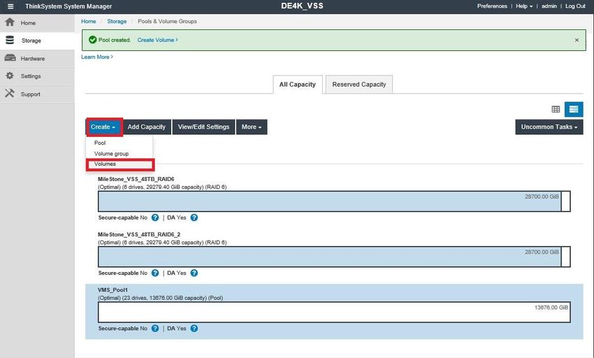
Next, click either the Create drop-down menu or the Create Pool button, shown in Figure 4.

Figure 4) Create a DDP pool.

From here, you see a Create Pool dialog box as shown in Figure 5. You must name your DDP pool and
select the drives that you want to use for this pool. After you name your pool and select your drives, click
the Create button at the bottom right. Your pool has now been created, and you are ready to begin
creating your volumes.
Figure 5) Name the pool and select drives for the pool.

After you create your pool, the dialog box in Figure 6 appears. Here, you can see that the pool called
VMS_Pool1 has 42451708.00GiB free, so now you can create some volumes. Click the Create drop-
down menu, and click Volumes.

 13     DE Series for Video Surveillance Best Practices Guide                 © 2020 Lenovo. All Rights Reserved.
Figure 6) Create a volume.

On DE Series systems, be sure to create at least two volumes on each system. Having two volumes
enables both controllers in the DE Series array to actively contribute to the performance of the system.
Figure 7 shows the creation of two volumes on VMS_Pool1. These volumes are named VMS_Vol1 and
VMS_Vol2.

 14     DE Series for Video Surveillance Best Practices Guide               © 2020 Lenovo. All Rights Reserved.
Figure 7) Create a volume (continued).

Figure 8 shows what the system configuration looks like after you have allocated all the storage on the
system.

 15     DE Series for Video Surveillance Best Practices Guide               © 2020 Lenovo. All Rights Reserved.
Figure 8) Example of final volume configuration.

 Note:      Before you can create hosts as shown in the following example, you must perform
            some setup on the attached server or servers. You can find those steps on the Lenovo
            Support Site under the software installation, configuration, and upgrade section for
            your OS.

 Because iSCSI is used as the protocol in this example, Figure 9 and Figure 10 show where
 you configure your iSCSI ports. To enable communication with the DE Series storage array,
 discovery from the host side is required. To navigate to Configure iSCSI Ports (Figure 10),
 click the Settings tab and then click the System tile as shown in Figure 9.

 Figure 9) iSCSI settings.

 In the System menu, scroll down to the iSCSI Settings section, which contains the Configure
 iSCSI Ports link that is shown in Figure 10. From there, you can configure your IPs for the
 iSCSI ports.
 Note:      Also outlined in Figure 10 is the target iSCSI Qualified Name (IQN). If you are

16       DE Series for Video Surveillance Best Practices Guide                © 2020 Lenovo. All Rights Reserved.
connecting to multiple DE Series storage arrays and need to differentiate between
arrays, this setting might come in handy.
Figure 10) iSCSI settings (continued).
Finally, after you create your volumes (and after you set up iSCSI sessions if you use the
iSCSI protocol), you can create hosts and map volumes to hosts. After you create your
volumes, return to the home screen, click the Storage tab on the left, and then click the Hosts
tile as shown in Figure 11.
Figure 11) Create a host.
After you click the Hosts tile, the dialog box in Figure 12 appears. Simply click Create Host.
17 DE Series for Video Surveillance Best Practices Guide © 2020 Lenovo. All Rights Reserved.Figure 12) Create a host (continued). In the following dialog box in Figure 13, you must provide a name for your host, select the OS, and select the IQN of the host. After you have completed that information, click Create, then your host is available for you to assign volumes to it. Figure 13) Host definitions. After you have defined the host, the dialog box in Figure 14 appears. Here, you click the Assign Volumes button and assign the volumes that you created previously. 18 DE Series for Video Surveillance Best Practices Guide © 2020 Lenovo. All Rights Reserved.
Figure 14) Assign volumes to the host.

 Figure 15 shows the Assign Volumes dialog box. Here, you see the volumes that you have
 created. Check the boxes next to the volumes that you want to assign to the particular host
 that you selected in Figure 14.

 Figure 15) Select volumes to assign.

 Finally, in Figure 16, you can see that VMS Host now has two volumes assigned to it. From
 the server side, you can now use the volumes as storage.

19     DE Series for Video Surveillance Best Practices Guide              © 2020 Lenovo. All Rights Reserved.
Figure 16) Host with assigned volumes.

 6 Server Considerations
 This section focuses on recording and failover server requirements.
 The recording server represents one or more instances of the hardware and software that are
 used to record live video or to archive video to the storage array. The software can run on a
 physical machine or as a guest on a virtual machine. The guest virtual machine must have the
 same virtual memory and virtual CPU as specified by the video management system software
 requirements for a physical machine.
 The number of networked video cameras per recording server and the resulting data rate are
 determined by the architecture and best practices that are documented by your VMS provider.
 As a general principle, and depending on your system hardware specifications, the amount of
 video that any individual server can process ranges from 100Mbps to 600Mbps.
 Table 7 lists the general recording server characteristics that Lenovo recommends.

 Table 7) Recording server characteristics that Lenovo recommends.

     Characteristic                  Description

     Form factor                     1 RU for space savings

     CPU                             Quad-core in the 2.0GHz to 2.9GHz frequency range

     RAM                             8GB or higher

     Network adapters                Integrated Ethernet adapters and PCI-based quad-port 1Gbps/10Gbps
                                     Ethernet for video ingress and, optionally, IP SAN connectivity

     Internal drives                 Dual RAID 1 (internal RAID controller) for a high-availability boot drive

     OS                              Windows 2012 or later

     Recording volume                NTFS (allocation unit size: 64KB)
     file system

 Note:        For the latest hardware and software requirements, go to your VMS provider’s website.

20         DE Series for Video Surveillance Best Practices Guide                            © 2020 Lenovo. All Rights Reserved.
6.1 Multipath I/O Device-Specific Module Installation
As described in section 4.5, High Availability, Lenovo DE Series arrays support multiple paths
to the LUNs from a server. To manage these paths, you must download the appropriate
Lenovo Storage Manager software from the Lenovo Support Site, and you must install the
software on each server.
Windows MPIO feature must be enabled first and the system is rebooted before installing the
Windows DSM. When you install the ThinkSystem Storage Manager software, use the Custom
installation option and then select the items that are shown in Figure 17. This step installs the
host MPIO DSM and the utilities files. If you are asked to start a background monitor process or
agent, do not select this option, or select No.
Figure 17) Lenovo ThinkSystem Storage Manager installation.
Note: For more help, go to the Lenovo Support Site.
6.2 DE Series LUN Discovery and Preparation
After the appropriate LUNs have been mapped to the recording server as shown in section 5,
Lenovo DE Series Storage Provisioning, you should perform the following steps:
1. Navigate to:
C:\Program Files\ThinkSystem\StorageManager\util
2. Run the command SMdevices; it should list all the DE Series LUNs that are mapped to
the server and display various information, including the current and preferred
controllers.
3. Use the information that SMdevices reports to help you in mapping DE Series LUNs to
drive letters in the Windows Disk Management tool. The Windows Disk Management
tool identifies an DE Series LUN as a drive that must be initialized, formatted, and
mapped to a drive letter before I/O can be issued to that drive. The tool is used to view
and to set details, such as the configuration of drive type, volume name, and allocation
unit size. For video surveillance implementation, Lenovo recommends an allocation unit
21 DE Series for Video Surveillance Best Practices Guide © 2020 Lenovo. All Rights Reserved.size of 64KB.
Note: For more information about Windows Disk Management, read the overview from
Microsoft.
7 Networking Considerations
The network infrastructure for video surveillance deployments must meet the following
requirements:
Provide sufficient available capacity (bandwidth) to transport video.
Exhibit very low or no loss of IP video packets.
Feature network latency that is within a suitable range for the transport protocol
(TCP or User Datagram Protocol [UDP]) of the video feed.
Provide high availability through network redundancy and best practices in network design.
Satisfy the network security and services requirements.
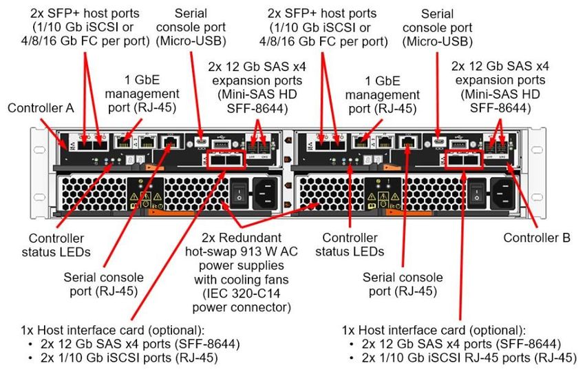
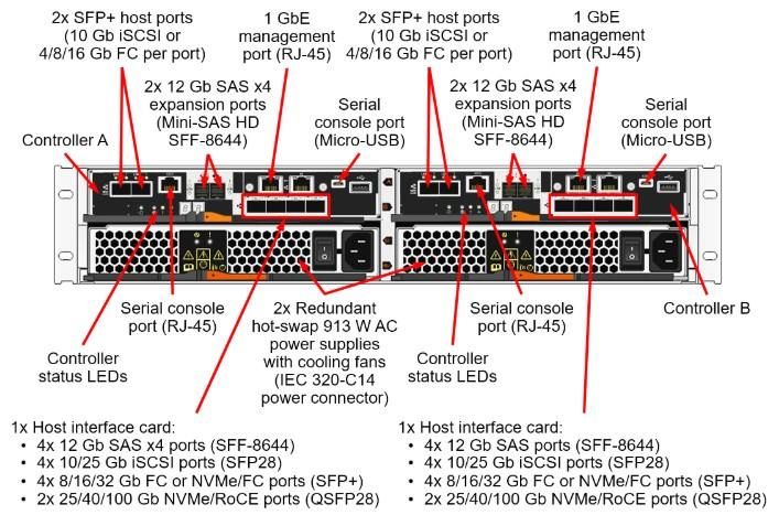
To meet the preceding requirements, for Lenovo DE Series systems, Lenovo recommends
a 10Gb Ethernet network at a minimum. The DE2000H, DE4000H and the DE6000H
systems have two onboard host ports per controller that support either 10Gb iSCSI or 16Gb
FC. Figure 18, Figure 19 and Figure 20 show these host ports on the top left of each
controller.
For iSCSI deployments, the use of multiple Ethernet network interface cards (NICs)
connecting to dual IP SANs also provides high availability to the DE Series controllers. For
other protocols, such as FC or SAS between the server and the DE Series controllers, dual-
port host bus adapters (HBAs) provide redundant paths to each controller.
22 DE Series for Video Surveillance Best Practices Guide © 2020 Lenovo. All Rights Reserved.Figure 18) Back view of the DE2000 controller. 23 DE Series for Video Surveillance Best Practices Guide © 2020 Lenovo. All Rights Reserved.
Figure 19) Back view of the DE4000 controller.

24        DE Series for Video Surveillance Best Practices Guide   © 2020 Lenovo. All Rights Reserved.
Figure 20) Back view of the DE6000 controller.
7.1 Traffic Management
To maintain a high-performing network, use multiple NICs to separate the camera
network, the client network, and SANs. By separating these networks, you gain the
following benefits:
Increased performance. By separating the traffic, you eliminate the impact
on recording performance that a high load on a client network might have.
Stability. With separated networks, interference on the client network does not affect
the camera network, which promotes predictable performance.
Increased security. No accidental or intentional interference with camera operations
occurs. By isolating the camera network, you eliminate the possibility of devices sending
information through the internet without your knowledge or permission.
Improved management. Management is also easier because the load is independent
to each network. These independent loads make it easier to calculate and to measure
the bandwidth usage on each network.
Note: As a best practice, be sure to eliminate single points of failure. An example is to
implement a secondary SAN switch. If a switch fails, your recording servers have
an additional path to your Lenovo DE Series storage and cameras can continue
recording.
25 DE Series for Video Surveillance Best Practices Guide © 2020 Lenovo. All Rights Reserved.Where to Find Additional Information
To learn more about the information that is described in this document, review the following
documents and websites:
Virtualizing Video Management Systems with Lenovo DE Series Storage
https://datacentersupport.lenovo.com/
ThinkSystem Storage Documentation
https://thinksystem.lenovofiles.com/storage/help/index.jsp
Contacting Support
You can contact Support to obtain help for your issue.
You can receive hardware service through a Lenovo Authorized Service Provider. To locate a
service provider authorized by Lenovo to provide warranty service, go to
https://datacentersupport.lenovo.com/serviceprovider and use filter searching for different countries.
For Lenovo support telephone numbers, see https://datacentersupport.lenovo.com/supportphonelist
for your region support details.
26 DE Series for Video Surveillance Best Practices Guide © 2020 Lenovo. All Rights Reserved.Notices
Lenovo may not offer the products, services, or features discussed in this document in all
countries. Consult your local Lenovo representative for information on the products and
services currently available in your area.
Any reference to a Lenovo product, program, or service is not intended to state or imply that
only that Lenovo product, program, or service may be used. Any functionally equivalent
product, program, or service that does not infringe any Lenovo intellectual property right may
be used instead. However, it is the user's responsibility to evaluate and verify the operation of
any other product, program, or service.
Lenovo may have patents or pending patent applications covering subject matter described in
this document. The furnishing of this document is not an offer and does not provide a license
under any patents or patent applications. You can send inquiries in writing to the following:
Lenovo (United States), Inc.
8001 Development Drive
Morrisville, NC 27560
U.S.A.
Attention: Lenovo Director of Licensing
LENOVO PROVIDES THIS PUBLICATION “AS IS” WITHOUT WARRANTY OF ANY KIND,
EITHER EXPRESS OR IMPLIED, INCLUDING, BUT NOT LIMITED TO, THE IMPLIED
WARRANTIES OF NON-INFRINGEMENT,
MERCHANTABILITY OR FITNESS FOR A PARTICULAR PURPOSE. Some jurisdictions do
not allow disclaimer of express or implied warranties in certain transactions, therefore, this
statement may not apply to you.
This information could include technical inaccuracies or typographical errors. Changes are
periodically made to the information herein; these changes will be incorporated in new editions
of the publication. Lenovo may make improvements and/or changes in the product(s) and/or
the program(s) described in this publication at any time without notice.
The products described in this document are not intended for use in implantation or other life
support applications where malfunction may result in injury or death to persons. The information
contained in this document does not affect or change Lenovo product specifications or
warranties. Nothing in this document shall operate as an express or implied license or indemnity
under the intellectual property rights of Lenovo or third parties. All information contained in this
document was obtained in specific environments and is presented as an illustration. The result
obtained in other operating environments may vary.
Lenovo may use or distribute any of the information you supply in any way it believes appropriate
without incurring any obligation to you.
Any references in this publication to non-Lenovo Web sites are provided for convenience only
and do not in any manner serve as an endorsement of those Web sites. The materials at those
Web sites are not part of the materials for this Lenovo product, and use of those Web sites is at
your own risk.
Any performance data contained herein was determined in a controlled environment. Therefore,
the result obtained in other operating environments may vary significantly. Some measurements
may have been made on development-level systems and there is no guarantee that these
measurements will be the same on generally available systems. Furthermore, some
measurements may have been estimated through extrapolation. Actual results may vary. Users
of this document should verify the applicable data for their specific environment.
27 DE Series for Video Surveillance Best Practices Guide © 2020 Lenovo. All Rights Reserved.Trademarks LENOVO, LENOVO logo, and THINKSYSTEM are trademarks of Lenovo. All other trademarks are the property of their respective owners. © 2020 Lenovo 28 DE Series for Video Surveillance Best Practices Guide © 2020 Lenovo. All Rights Reserved.
You can also read