Object-Wise Video Editing - Article - MDPI
←
→
Page content transcription
If your browser does not render page correctly, please read the page content below
applied
              sciences
Article
Object-Wise Video Editing
Ashraf Siddique                and Seungkyu Lee *

                                           Department of Computer Science and Engineering, Kyung Hee University, Seoul 02447, Korea;
                                           siddique2127@khu.ac.kr
                                           * Correspondence: seungkyu@khu.ac.kr; Tel.: +82-1091979285

                                           Abstract: Beyond time frame editing in video data, object level video editing is a challenging
                                           task; such as object removal in a video or viewpoint changes. These tasks involve dynamic object
                                           segmentation, novel view video synthesis and background inpainting. Background inpainting is a
                                           task of the reconstruction of unseen regions presented by object removal or viewpoint change. In
                                           this paper, we propose a video editing method including foreground object removal background
                                           inpainting and novel view video synthesis under challenging conditions such as complex visual
                                           pattern, occlusion, overlaid clutter and variation of depth in a moving camera. Our proposed method
                                           calculates a weighted confidence score on the basis of normalized difference between observed depth
                                           and predicted distance in 3D space. A set of potential points from epipolar lines from neighbor
                                           frames are collected, refined, and weighted to select a few number of highly qualified observations
                                           to fill the desired region of interest area in the current frame from video. Based on the background
                                           inpainting method, novel view video synthesis is conducted with arbitrary viewpoint. Our method
                                           is evaluated with both a public dataset and our own video clips and compared with multiple state of
                                           the art methods showing a superior performance.

                                           Keywords: object removal; background inpainting; novel view video synthesis; image based render-
                                           ing, epipolar geometry


                                           1. Introduction
Citation: Siddique, A.; Lee, S.
                                                Video editing at the object level is a challenging task due to the difficulties of dynamic
Object-Wise Video Editing. Appl. Sci.
2021, 11, 671. https://doi.org/
                                           object region segmentation and novel view video synthesis. Inserting a new object or
10.3390/app11020671
                                           removing an unexpected object from a video are challenging but interesting tasks. In both
                                           tasks, background inpainting for filling a missing region after object removal is a critical
Received: 31 October 2020                  part of realistic new video synthesis. The missing region has to be appropriately inferred
Accepted: 7 January 2021                   from given background information in the video.
Published: 12 January 2021                      One of the familiar inpainting algorithms from single images is the exemplar-based
                                           approach introduced in References [1,2]. The exemplar-based approach generates quick
Publisher’s Note: MDPI stays neu-          inpainting outputs when the hole is comparatively small. On the other hand, it suffers from
tral with regard to jurisdictional clai-   insufficient visual coherence globally for bigger holes. The most critical and important
ms in published maps and institutio-       aspect of the video inpainting method is how consistently random holes are filled with
nal affiliations.                          appropriate information in both space and time dimensions. It can be performed by the
                                           single image inpainting approach which considers patches over the neighbour frame,
                                           taking into account the flow of motion information [3–6] or global-space time consistency
                                           optimized by the global minimization energy function [7].
Copyright: © 2021 by the authors. Li-
censee MDPI, Basel, Switzerland.
                                                The existing inpainting methods are not suitable for dealing with a video including
This article is an open access article
                                           dynamic objects and complex video scenes taken from a moving camera, which is common
distributed under the terms and con-
                                           in many video clips captured by daily used devices like smartphones. To overcome such
ditions of the Creative Commons At-        problems, inter-frame registration and respective pixel-wise calibration throughout the
tribution (CC BY) license (https://        frames in a video are needed. Motion-based alignment techniques for inpainting are
creativecommons.org/licenses/by/           proposed in References [8–11]. These methods try to compute the motion information of
4.0/).                                     each pixel or patch to find the flow of camera movement throughout the video. A robust and

Appl. Sci. 2021, 11, 671. https://doi.org/10.3390/app11020671                                               https://www.mdpi.com/journal/applsci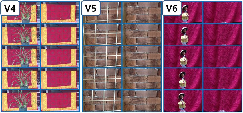
Appl. Sci. 2021, 11, 671                                                                                          2 of 22

                           fast alignment between the cameras can be performed using Homography transformation
                           calculated from sparse key-points. Homography-based approaches are usually suitable for
                           video editing tools to handle the problem of camera movement [10,12]. However, the single
                           Homography transformation matrix is not capable of estimating dense corresponding
                           points of the missing region in video inpainting task.
                                 In 3D video editing, inpainting methods show a reasonable performance when the
                           measurement of 3D information is accurate. Inpainting in 3D space can be performed
                           when accurate 3D translation matrix between frames is possible to be extracted. However,
                           calculation of accurate transformation matrix with moving camera is not a trivial task,
                           where scene space relationship among the frames benefits diverse 3D video processing [13].
                           A Homography based inpainting method introduced in Reference [10] considers 3D scene
                           information having piece-wise planner geometry to remove a moving object from video
                           taken with moving camera. To fill the background of moving object, they use a single
                           source frame based information maintaining the consistency of background color. A region-
                           based Homography approach is applied in video inpainting in Reference [12] with static
                           and moving cameras. Considering the computational complexity of their methods, they
                           consider the alignment between groups of neighboring frames. The alignment among the
                           neighboring groups is calculated by minimizing an energy function of both spatial and
                           temporal coherence. A sampling-based approach proposed in Reference [14] which allows
                           to perform high quality video processing like denoising, super-resolution, inpainting,
                           and deblurring. They consider the utilization of redundant scene information over the
                           frames of video instead of improving a separate 3D scene information producing rather
                           blurry inpainting results. And it requires human intervention to remove the foreground
                           object point cloud from the scene to get the background depth.
                                 Another important task in video editing is novel view synthesis. Reconstructing
                           a different view image or video in computer vision is a challenging task. Over the
                           past few decades, several Novel View Synthesis (NVS) methods have been introduced
                           such as view warping [15] and interpolation [16]. An image-based rendering (IBR) by
                           sampling a plenoptic function from a dense matrix of camera view was introduced in
                           References [17–19]. These methods work well when input views are separated by larger
                           baseline. Novel view synthesis becomes more challenging task with wider baselines due to
                           scale change, 3D rotation and foreshortening effect of the objects. The idea of IBR based
                           on the 3D modeling is introduced in Reference [20] using multi-view stereo. Because of
                           impressive development of 3D reconstruction techniques from multi-view images [21], we
                           can obtain a novel view image based on the target pose of camera as input. Rather than
                           reconstructing dense point, Reference [22] takes advantage of the sparse point obtained
                           from the Structure-from-motion combined with the segmented region where each segment
                           is considered as a planar associated with homography transformation. Reference [23]
                           proposes an improved pipeline of better representation of 3D scene for NVS.
                                 In this paper, we propose a novel and robust video editing method under several
                           challenging background situations like complex visual pattern, occlusion, overlaid object
                           clutter, and depth variation observed from a moving camera which is the extension of
                           previous work [24]. First, our method obtains 3D point cloud and camera translation matrix
                           of video frames using a Structure From Motion (SfM) method. Based on the obtained 3D
                           location of the camera for each frame, our method computes a confidence score relying
                           on the normalized difference between the depth (observed distance) and 3D distance to
                           the ray segment in 3D space (predicted distance). The difference between observed depth
                           and prediction distance quantifies the confidence of the potential point. We collect all
                           the points from the truncated epipolar line from neighbor frames and those points are
                           called as potential points in our inpainting step. After collecting all potential points, we
                           select a few highly qualified potential background points based on the confidence score.
                           Then we apply weight and ranking on the selected highly qualified potential points to
                           fill missing regions in video editing. Finally, we correct the noisy pixel by calculating the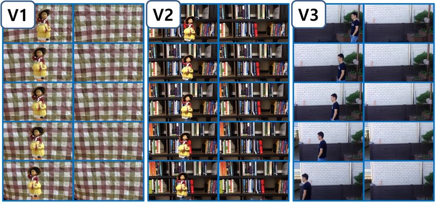
Appl. Sci. 2021, 11, 671                                                                                            3 of 22

                           temporal coherence between inpainted frames. The sample result of our method is shown in
                           Figure 1 compared with the state of the art method [14].
                                The contributions of our work include (1) a novel confidence score based on the
                           normalized difference between depth and 3D distance to ray segment in 3D space (NDD)
                           enabling simple but effective video editing in 2D image space, (2) a unified framework of
                           optimal corresponding point collection for video editing that addresses occlusion, complex
                           visual pattern, overlaid object clutter and depth variation problems in the background,
                           (3) depth videos are calculated using photo-consistency over epipolar line of neighbour
                           frames, (4) Our new view video synthesis using NDD produces the scene behind the
                           foreground object to see background, (5) outperforming video editing results over state-
                           of-the-art methods on both the public data set and our own video clips with various
                           challenging conditions in novel view video synthesis.

                           Figure 1. Our video inpainting result compared to state of the art [14] method. More comparison
                           results are demonstrated in Figures 13–15.

                           2. Object Removal and Background Inpainting
                                Object removal and background inpainting in video are essential tasks in video editing.
                           Our proposed background inpainting method is inspired by Reference [14]. The workflow
                           of our object removal and background inpainting is shown in Figure 2.
                                To inpaint background of each foreground object pixel of a current video frame, a pixel
                           ray (dotted red line in Figure 3) is drawn in 3D space from the camera location which
                           intersects both foreground object and background behind the object. We observes only the
                           foreground object and the intersecting point with background (point b in Figure 3) is hided
                           behind the foreground object. Background point b can be observed from some neighboring
                           frames with a condition of a moving camera or moving objects.
                                We truncate a segment of the pixel ray around the background surface which is shown
                           in Figure 3 with a solid red line. As the background surface is unknown in the current frame,
                           obtaining a good ray segment is very important in our method to include background
                           information and avoid foreground information. We prefer the ray segment does not have
                           any intersection with a foreground object that has to be removed. When the ray segment
                           intersects with the foreground, our inpainting results will be corrupted by the foreground
                           information. With other conditions, if the ray segment does not have any intersection with
                           the background, our method fails to gather background information. Therefore, initially,
                           we put the range of ray segments from a certain distance behind the foreground object to be
                           removed to the farthest distance of the scene which makes sure of intersecting background.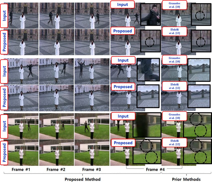
Appl. Sci. 2021, 11, 671                                                                                                     4 of 22

                           Figure 2. The workflow of our object removal and background inpainting method.

                                  Figure 3. Ray segment in 3D space intersect with background surface and corresponding truncated
                                  epipolar lines for potential background point collection from 2D reference frames of input video.

                                       Even though the initial ray segment is long, we optimize the range of the ray segment
                                  with the calculated normalized difference of depth-3D distance (NDD) in Section 2.2.1. We
                                  project the pixel ray shown in Figure 3 to 2D image plane using a transformation matrix
                                  calculated from SfM step and 2D plane observe a line called epipolar line. Each frame
                                  obtain a truncated epipolar line after projecting the ray segment to the neighbouring frame.
                                  Each 2D point on the truncated epipolar line is considered as a potential point for the
                                  background information extraction for the current frame. The background intersecting
                                  point exist on the truncated epipolar line unless the point is occluded by the foreground
                                  object which is shown in Figure 3.
                                       Our method tries to find highly qualified points among the potential points on the
                                  truncated epipolar line. For each ith frame from input video Fi , the binary mask Mi is
                                  given to removed the object region from all frames from the input video. If the video of the
                                  mask was not given, we create the mask Mi of the object from the video using method [25]
                                  where only 1st frame annotate mask is considered as an input. Point p represents the pixel
                                  of the foreground region that has to be removed which is decided from mask Mi . Since
                                  the binary mask Mi does not have to be so precise, we dilate the calculated mask Mi to
                                  ensure every pixel of the foreground object should be considered for background inpaintng
                                  in our method. Crgb ( p) (Crgb ( p) ∈ R3 ) represents the color that is used to fill the point p
                                  after the foreground object removed. The main goal of our method is to estimate Crgb ( p)
                                  from the observation of neighboring frames. A potential set of points S( p) are used to
                                  calculate the Crgb ( p) for point p in current frame where S( p) = {s| points of all truncated
                                  epipolar line projected from pixel ray of point p}. Crgb (s) represents color information of a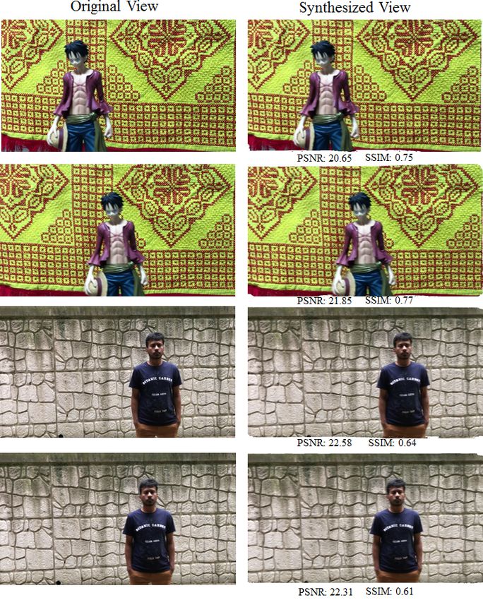
Appl. Sci. 2021, 11, 671                                                                                              5 of 22

                           potential point s (Crgb (s) ∈ R3 ). Then Crgb ( p) is calculated as weighted sum of Crgb (s) of
                           all s ∈ S( p) give.
                                                                       ∑ w(s) ∗ Crgb (s)
                                                                        s∈S( p)
                                                          Crgb ( p) =                      ,                             (1)
                                                                                  ∑ w(s)
                                                                             s∈S( p)

                           where w(s) is a confidence score calculated from our normalized difference of depth-3D
                           distance (NDD) that will be explained in detail in the following subsections. In fact,
                           potential point set S( p) will be refined further in the following steps discarding explicitly
                           poor potential points such as foreground point, background occluded points or outlier
                           background point with a clearly different color.

                           Figure 4. 3D point cloud and transformation matrix between frames are extracted from structure
                           from motion (SfM) using all input video frames. Depth map of each frame is obtained by projecting
                           3D points and interpolating them at each 2D image space.

                           2.1. Prepossessing
                                To remove an object from a video, we need a mask of an object in each frame of input
                           video which indicates the desired region that has to be removed. In our method, we accept
                           a given mask of all frames of input video, however we also can compute the mask of the
                           object on all frames considering the mask of the first frame as input which is described in
                           Section 2.1.1.
                                In order to calculate the truncated epipolar line at each neighboring frame, we need to
                           know the camera transformation matrix between them. Using all video frames, we estimate
                           the 3D point cloud and transformation matrix between frames from SfM (Structure from
                           Motion) method [26] shown in Figure 4. With the given transformation matrix, a depth
                           map of each frame is also obtained by calculating photo-consistency over the epipolar
                           geometry or projecting the 3D points onto the 2-dimensional image space of each frame.
                           The depth extraction methods are described in Section 2.1.2.

                           2.1.1. Object Mask Extraction
                               Segmenting a foreground object from a video sequence is an important task in video
                           analysis and editing in commercial applications. An unsupervised method of foreground
                           segmentation is a fully automatic method that does not need any human intervention.
                           The main source of this kind of segmentation is visual saliency [27] and motion like optical
                           flow [28]. However, foreground object segmentation in a video sequence is often an
                           ambiguous task because of a desired object is not fixed. Therefore, unsupervised object
                           segmentation does not apply to the interactive video editing scenario.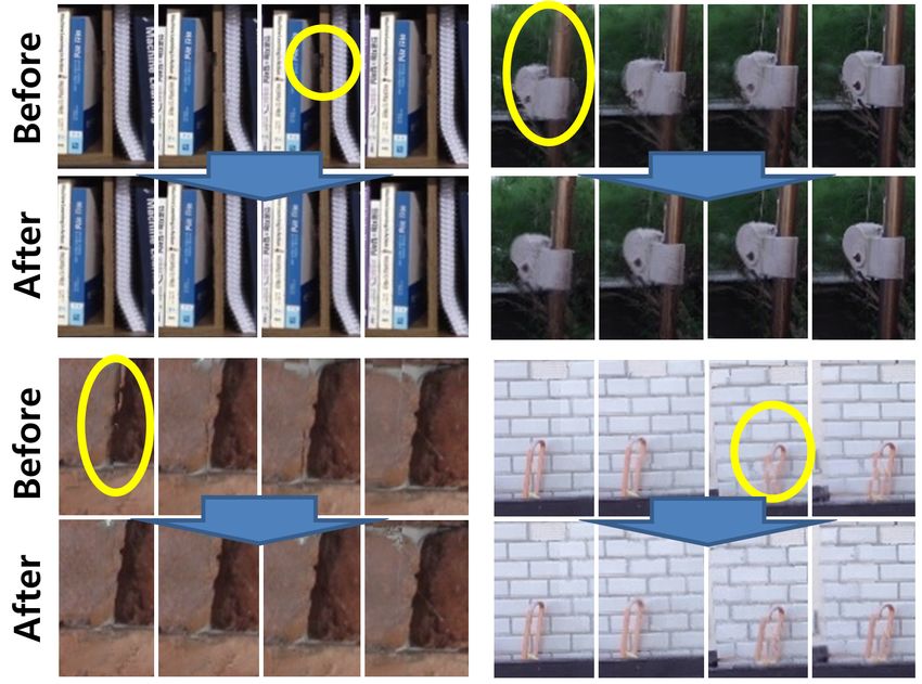
Appl. Sci. 2021, 11, 671                                                                                                  6 of 22

                                Rather than concentrating on the unsupervised method, we extract the object mask
                           using a method described in Reference [25] with given a reference frame object mask and
                           input video. The goal of this method is to segment the target object that has to be removed
                           from the entire video sequence. To make use of both the previous mask to generate the
                           current frame and the reference frame that specifies the target object, a Siamese encoder-
                           decoder network is described in Reference [25].

                           2.1.2. Depth Extraction
                                 The depth map of each frame is obtained by projecting the 3D points onto the 2-
                           dimensional image space of each frame. The depth value at each pixel is calculated by
                           interpolating the depth of projected 3D points falling within a patch of the fixed size
                           described in Reference [24]. We simply perform a depth calculation for the points from
                           overlaid multiple surfaces by selecting the closest group of points within the patch. If we
                           do not have a large enough number of 3D points within the patch, we increase the patch
                           size making a smoother depth map. In this case, sparse 3D points cause a big hole in the
                           depth map and larger patch size causes poor depth near the edge of the object that has a
                           noticeable difference in depth. On the other hand, the wrong 3D points cause noisy depth.
                                 In order to find the depth δ( x ) of each pixel x, we draw a pixel ray that intersects
                           the scene at a certain depth. The similar color observation of certain depth on the pixel
                           ray from different given views can be potential depth δ( x ) of the output pixel of current
                           frames Fi . The ray that would be measured by the pixel denoted x in Figure 5 is marked
                           by the red line passing through that pixel. To find the depth along the red line, we have
                           to locate the position of the intersecting point between the red line and the scene on the
                           basis of similar observation with pixel x from neighboring frames of the input video. In
                           this context, the ray segment should cover the whole range of the scene to collect both the
                           foreground or background information. We collect all observations of each point in the
                           red line from different neighboring frames, which is shown on the right side of Figure 5.
                           Along the red line, the highest photo-consistency observed from neighboring frames can
                           be a potential location to measure δ( x ) of pixel x. However, it is a challenging task to find
                           the depth location along the red line due to the presence of uniform area and occlusion in
                           the scene when all neighbor frames are used to calculate the score of photo-consistency.

                           Figure 5. Calculate the depth of pixel x from the similar observation from neighbouring frames along
                           the epipolar line. Top right of the figure showing the color observed at a range of depth along the
                           pixel ray across the neighbouring frames where depth is along the vertical axis and input frame along
                           the horizontal axis. The minimum scores along the depth represent highest photo-consistency which
                           represent the depth location for pixel x.

                                To avoid any occlusion, we divide the neighbouring frames into two groups (Left
                           side frames and Right side frames) based on the location of the current frame. In Figure 6,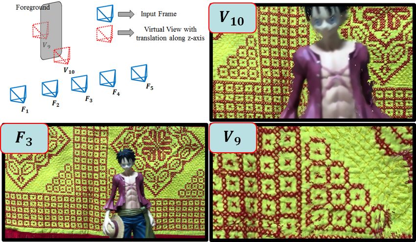
Appl. Sci. 2021, 11, 671                                                                                              7 of 22

                           the pixel x can be occluded either from the left-side or right-side neighbouring frames of
                           input video from the current frame. In Figure 6, we carefully select four pixel x1 , x2 , x3
                           and x4 around the edge of an foreground object where x2 and x4 are on the foreground
                           object and x1 and x3 are on the background of the scene. Pixel x1 and x3 is occluded from
                           right and left side frames respectively from the current frame. Considering this fact, we
                           calculate the photo-consistency score L x (z) from the left frames and R x (z) from the right
                           frames shown in Equations (2) and (3) along the direction of depth z. We notice that,
                           the highest photo-consistency is found for point x1 from L x (z) and point x3 from R x (z)
                           along the depth z. The right and left side neighbouring frames are selected based on the
                           3D location of the neighbouring camera from current frames camera position. The pixel x2
                           and x4 can be observed from both left and right side frame and show the highest photo-
                           consistency at same depth in L x (z) and R x (z) scores shown in Figure 6. To calculate δ( x ),
                           we use minimum scores from both L x (z) and R x (z) along the depth z which is shown in
                           Equation (4).
                                                                 1 i
                                                                 n l =∑
                                                       L x (z) =           | Pi ( x, z) − Pl ( x, z)|                 (2)
                                                                      i −n

                                                                          i +n
                                                                     1
                                                         R x (z) =
                                                                     n     ∑        | Pi ( x, z) − Pr ( x, z)|           (3)
                                                                         r = i +1

                                                         δ( x ) = arg min(min( L x (z), R x (z))).                       (4)
                                                                           z

                                Here, Pi ( x, z) represents an image patch of current frame Fi centered on the location
                           where the 3D location along the ray of pixel x at depth z is projected. i is the index of
                           current frame n is the number of left frames. We use equal number of frames for the left
                           side and right side assuming uniform speed of camera motion.

                           Figure 6. Occlusion handling by calculate the photo-consistency scores considering either left or
                           right side frames to predict the depth of pixel x.

                           2.2. Potential Point Set Collection
                                For image pixel p from the current frame, we collect a potential point set S( p) which
                           includes all points on the truncated epipolar lines projected on neighboring frames from
                           a pixel ray segment of p. In prior work [14], they consider a small frustum segment of
                           pixel p and projected to neighbor frames that create a region rather than an epipolar line.
                           They collect all potential points from the projected region for noise reduction and the
                           object removal method consider the redundancy of color information with a lack of precise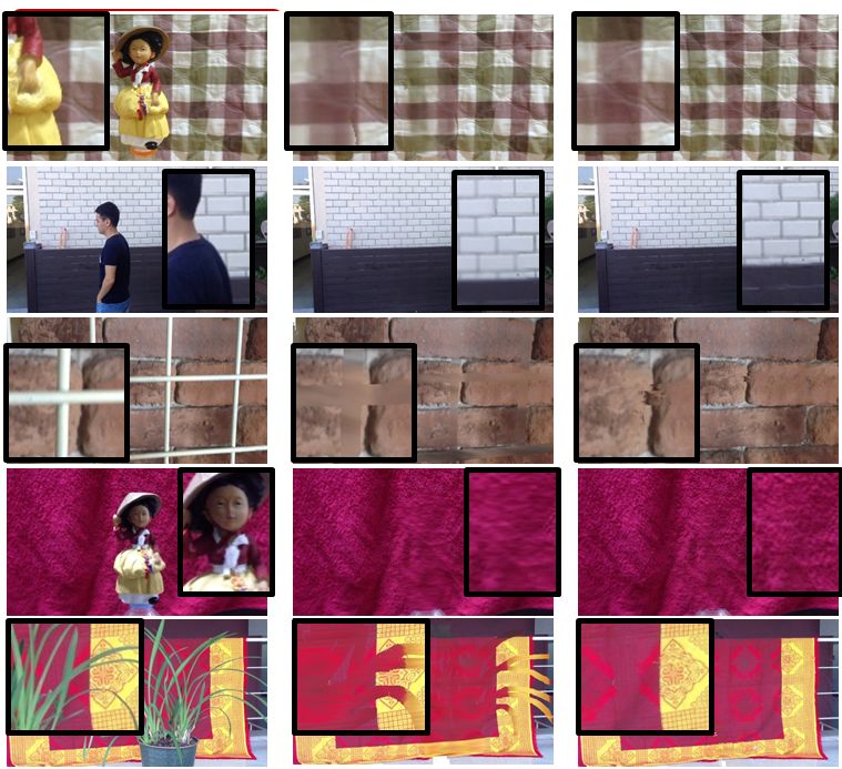
Appl. Sci. 2021, 11, 671                                                                                           8 of 22

                           calculation of confidence for the output pixel. In our inpainting method for object removal,
                           we propose a confidence scores based on NDD measurement step which enables us to select
                           a very small number of highly qualified potential points out of point set S( p). However,
                           single pixel 3D frustum mostly is projected as a line in the 2D image and the most qualified
                           potential points can be located in the near neighboring frames holding similar distance to
                           the background surface along the lines.
                                Thanks to our precise NDD measurement and for light and effective algorithm, we
                           draw a truncated epipolar line instead of a frustum. We collect all points that have less than
                           1 pixel distance from the truncated epipolar line from all neighbor frames constructing
                           potential point set S( p).

                           2.2.1. Normalized Difference of Depth-3D Distance
                                 After collecting all potential points set S( p) from all truncated epipolar lines, we
                           measure the confidence of each potential point by calculating the normalized difference
                           between depth and 3D distance to the ray segment in 3D space (NDD). As the ray segment
                           in 3D space is a parameterized line and the location of the current frame and neighboring
                           frames are known, 3-dimensional Euclidean distance to the ray segment can simply calcu-
                           late between two 3D points. A difference of depth-3D distance quantifies the discrepancy
                           between the predicted distance (assuming that the current observed point is from the 3d
                           position where background surface intersects ray segment) and depth (observed distance).
                           In order to find the missing point behind the foreground object correctly, we have to know
                           the corresponding position b of the background shown in Figure 7a which is the inter-
                           secting point between the ray segment and background surface. The depth-3D distance
                           becomes zero at the position b where the ray segment lies as the red line and background
                           are intersect each other.
                                 In other words, if any potential point s is a correct observation of point b from the
                           neighboring frame, the corresponding depth of point s and 3-D Euclidean distance between
                           3D point b and camera should be identical. However, the depth-3D distance of the same
                           observed background from different view changes along with viewpoint changes shown
                           on the right side of Figure 7a. So only depth-3D distance provides different confidence
                           scores for the same point on background in neighboring frames with a different view.
                           Therefore, we consider the normalized difference of depth-3D distance (NDD) as confidence
                           scores shown in Figure 7b as a blue line and the calculation. NDD is the 3D distance
                           along the perpendicular direction from the observed background to the ray segment.
                           NDD still provides a linear measurement of the discrepancy between the depth (observed
                           distance) and 3D distance (predicted distance) assigning consistent confidence scores for
                           identical points. Figure 8a and Equation (5) demonstrate how NDD is really calculated in
                           method [24].

                                                                         α             δ(s) − β
                                                  NDD (s) = abs(γ ×        ) = abs(γ ×          )
                                                                         β                β
                                                                      δ(s) × (q1 + q2)
                                                       = abs(γ × (                     − 1)),                         (5)
                                                                     d1 × q2 + d2 × q1
                                                                                        d1×q2+d2×q1
                           where δ(s) = α + β is depth of potential point s and β ≈      q1+q2   . β is approximated
                           from the ratio between q1 and q2 (image space distance) and d1 and d1 (3d distance in
                           camera space) as illustrated in Figure 8a. γ is 3d distance from s to light ray of current
                           frame along the perpendicular line.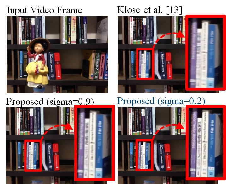
Appl. Sci. 2021, 11, 671                                                                                                      9 of 22

                                (a)                                                  (b)                      (c)
      Figure 7. (a) Difference of depth-3D distance; (b) Normalized difference of depth-3D distance (NDD); (c) Threshold the
      NDD to refined the potential set of points.

                                (a)                                                              (b)

      Figure 8. (a) Normalized difference of depth-3D distance (NDD) calculation in method [24] based on the distance ration
      of q1 and q2 in epipolar line from image space; (b) NDD is calculated in 3D space from a triangle which is created by two
      camera position c1 and c2 and intersecting point o between pixel ray of point s and the truncated ray shown as red line.

                                      However, in this method, the approximate NND distance is calculated from the
                                 ratio between q1 and q2 image space distance which is not compatible with the distance
                                 ratio in the 3D space. Instead of approximating the NDD distance from 2D space from
                                 Reference [24], we calculate NDD in 3D space which is illustrated in Figure 8b make our
                                 method more robust video processing having a different scale of depth in the scene. β is
                                 calculate from the triangle created from two camera position and the point of intersection
                                 o between pixel ray of point p and pixel ray of point s (potential points for pixel p from
                                 truncated epipolar line from neighbouring frames). In the Figure 8b c1 c2 are two camera
                                 position in 3D space and the point o is the intersection between two pixel ray. So from given
                                                                                                                 sin( B)
                                 two line equation and two given camera position, we calculate β = sin(180−( A+ B)) × γ.
                                 Finally the Equation (5) becomes

                                                                            δ(s) × sin(180 − ( A + B))
                                                     NDD (s) = abs(γ × (                               − 1)).                     (6)
                                                                                    γ × sin( B)

                                      Here, A and B is the angle made by the triangle shown in Figure 8b at the camera
                                 position c1 and c2 respectively. γ is the perpendicular distance of camera position c1 from
                                 the pixel ray of p.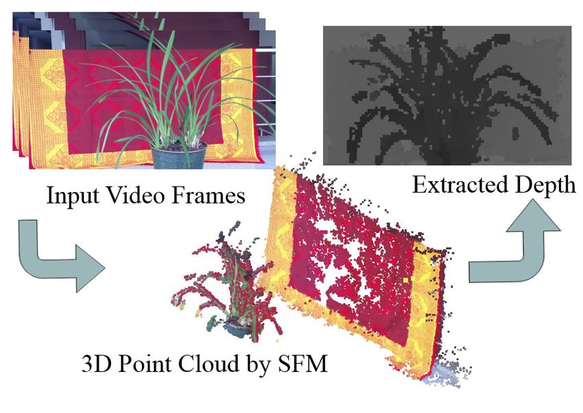
Appl. Sci. 2021, 11, 671                                                                                             10 of 22

                           2.2.2. Ray Segment Refinement
                                As the background point of ray-segment is unknown, the ray segment refinement step
                           ensures to include the background point inside the ray segment. As we mentioned before,
                           the initialization of the ray segment is not optimal. After calculating the NDD value for
                           all potential points on the truncated epipolar line from a single frame, we obtain NDD
                           distribution shown in Figure 7c. The optimal ray segment can be achieved by investigating
                           the NDD distribution. First, we investigate the initial ray segment that really intersects
                           with the background by observing the NDD distribution. If the ray segment intersects
                           with the background, NDD distribution has to touch the horizontal axis (point index along
                           the epipolar line) at least once. If the initial ray segment has no intersection with the
                           background (Figure 9), we shift the ray segment along the direction where calculated
                           NDD values become smaller (so that we can find the minimum point that intersects the
                           horizontal axis). When the ray segment adjustment is finished, we farther optimize the size
                           of the ray segment putting a threshold in NDD values shown in Figure 9.

                           Figure 9. Ray segment range shift: If ray segment does not intersect background, we shift our ray
                           segment toward the side where calculated NDD values become smaller so that we can meet the
                           minima point touching the axis.

                                As we know that high potential points for pixel p are located in the minimal point of
                           NDD distribution, we drop all potential points that have bigger NDD values in S by giving
                           a threshold. The size of a pixel in 3D space on the background surface is propositional to
                           the depth of that pixel. We decide the potential points should have a smaller value than
                           single pixel size in 3D. We can easily calculate the pixel size taking the rectangle size of a
                           certain depth of pixel frustum.

                           2.2.3. Frame Selection
                                In the ray segment refinement step, we assume that our refined ray segments are
                           located in a good position and have intersected with an occluded background. In the
                           real world environment with complex shape background, neighboring frames could have
                           failed to observe the desired occluded background even though the ray segment have an
                           intersection with the background surface. However, we avoid the failure frames in our
                           final inpainting calculation. In Figure 10, we have shown three failure cases where the
                           desired background can not be observed.
                                Figure 10a is a “Invisible Background due to Close Foreground” case, where neighbor
                           frames may not see occluded background b. This situation mostly happened with the
                           nearest neighboring frames when the foreground object is bigger in size. If all points of
                           the truncated epipolar line from a single frame consist of a foreground region, this frame
                           is not considered for potential point collection. In this case, our NDD distribution curve
                           does not touch the horizontal axis (point index along the epipolar line) and monotonically
                           increases or decreases which indicates that the background point b can not be observed
                           from this viewpoint.
Appl. Sci. 2021, 11, 671 11 of 22
(a) (b)
(c)
Figure 10. Frame selection by investigating the distribution of NDD curve. (a) Invisible Background due to Close
Foreground; (b) Self Occlusion; (c) Overlaid Object Clutter in Background.
Figure 10b is a “Self Occlusion” case. If the background contains very complex shape,
desired background point b can be occluded by a different part of the background from the
viewpoint of the neighboring frame. In this case, the NDD curve has a local minima point
but never touches the horizontal axis. We have to discard this frame in the potential point
collection step as well. For the detection of this situation, we compare the NDD score at
the local minima of NDD curve with single 3D pixel size. If the score at local minima is
smaller than single 3D pixel size then self-occlusion occurred on that frame. Figure 10c is
a “Overlaid Object Clutter in Background”. In some case, the current frame has multiple
backgrounds behind the foreground object at point p. In this situation, our NDD curve
has multiple touches with the horizontal axis shown in Figure 10c. To inpaint the point p,
we have to find the closest background point from the NDD curve. We choose the closest
local minima point on the curve to collect the potential point for p and discard the farther
minima points from the potential points collection.
Therefore, our frame selection step discards all potential points from the potential
point collection step from the failure frames detected by the NDD curve. Finally, we get a
refined and highly qualified potential point set Ŝ( p) = {ŝ|qualified points on all truncated
epipolar lines for point p of the current frame} for point p after performing both “Ray
Segment Refinement” and “Frame Selection” steps.
2.3. Inpainting
After getting highly qualified potential point set Ŝ( p), we perform inpainting step to
get the background color information of point p using Equation (1). We give confidence
score w(ŝ) for all potential point ŝ based on the NDD values using the following equaiton:
NDD (ŝ)−µ 2
w(ŝ) = e−( 2σ )
, (7)
where µ is the mean NDD of all ŝ and σ is the standard deviation of the Gaussian function.
Figure 1 shows the effect of different σ. In our experiments, we set σ = 0.2.Appl. Sci. 2021, 11, 671 12 of 22
Figure 11. Sample Temporal Error Correction Results: Please see inside of yellow circles.
2.4. Temporal Error Correction
After calculating the color Crgb ( p) from Equation (1), temporal consistency between
neighbour frames is investigated to correct noisy inpainting result. To simplify this step, we
consider two consecutive frames. To correct the temporal error in the result, we calculate
the global displacement between every consecutive frame. We believe that consecutive
frames in a video have very Small displacement in the background pixel. We minimize the
sum of squared distance between patches taken from both inpainted (background) regions
from our proposed method. We get very small displacement between the frames in the
subpixel level (1/4 pixel distance) because the movement between consecutive frames is
very small. The image patch and the range of the search space are automatically selected
based on the input mask of the foreground. After finding the global displacement, we
estimate the noisy pixel based on the absolute difference between the inpainted pixel.
Bigger differences between the pixel indicate temporal inconsistency. We replace the wrong
pixel color values sequentially over the neighbor frame when the difference is big. However,
it is very difficult to decide which alternate pixel color is correct in the inpaited result frame.
We only trust the pixel outside of the inpainted region and the pixels that are replaced
by non-inpaited pixel. This method sequentially corrects inconsistent error point passing
over the correct value from outside of the inpainted region frame by frame. We employ
this method to avoid any complex and computationally expensive global optimization
with all inpainted points from all frames. If inconsistency happens suddenly in the middle
of the inpainted background, the corresponding point at neighbor frames also could be
non-corrected inpainted point as well (so we cannot trust any). In such a case, we trace
back through further neighbor frames until we find either non-inpainted point or inpainted
but corrected point. The effects of Temporal Error Correction in our background inpainting
results are shown in Figure 11.
3. Novel View Video Synthesis
In our proposed Novel View Video Synthesis (NVVS) method, we create a virtual
camera in 3D space near the path of the input video. To render the novel view from the
manually created virtual camera, we draw the pixel ray of pixel p of the novel view which
intersects with the 3D scene. Here, the first intersection in the pixel ray from point p is
considered as the potential position to collect color information from neighboring frames
from potential points set S( p) using Equation (1). The point p represents the entire pixel of
the view from the virtual camera created in 3D space. The only difference in the NVVS
method from object removal is the truncated ray segment of pixel ray. To inpaint bothAppl. Sci. 2021, 11, 671 13 of 22
foreground and background, the ray segment should cover the whole scene in 3D space
which is shown in Figure 12a with a red line. In this figure, the pixel p need to collect
color information of a smaller region from the closer object surface. On the other hand,
the farther object surface in 3D space contains a bigger region for pixel p. The refined
potential points ŝ should have a smaller distance than the region created by the frustum of
single pixel p and the surface of the scene. As the NND curves do not always have zero
minima, the smaller fixed threshold for NDD can avoid a potential frame for collecting
refined point ŝ which can create artifacts when very few numbers of points are selected.
On the other hand, a bigger threshold for NDD distance can include multiple refined points
from the truncated epipolar 2D line from a single reference frame for a closer object shown
on the left side of Figure 12a. Applying a bigger threshold on NDD causes a blur effect on
the closer object and the background points near the object edge can collect foreground
information. To solve this problem, we give a threshold based on the 3D distance from
the novel view camera to the intersecting point between the pixel ray of p and pixel ray
of s. The distance can be calculated from the triangle shown in Figure 8b. The diagonal
Size of the single pixel frustum at distance from the Camera for each potential point s is
considered as the threshold which forces collection of one or very few significant potential
points from a single frame shown on the left side of Figure 12a. The distance ratio of the
neighboring pixel in the epipolar line (image space) and the red line is not the same. In the
valid range of the red line, closer distance has dense pixels and farther have a sparse pixels.
If the threshold is set as single pixel size then some potential background pixel can be
omitted from the refined point set collection. To include those, we consider the sub-pixel
level inside the epipolar line of the 2D image rather than increasing the pixel size in 3D
for threshold. In Figure 12b, we showed the comparison between the NVS result obtained
from a fixed threshold and adaptive threshold based on the 3D distance. A fixed threshold
creates a slightly blurred result when a bigger threshold is set for avoiding artifacts and
our proposed threshold method based on 3D distance obtained more sharper result.
(a) (b)
Figure 12. NDD Thresholding to collect more potential points to reduce the effect of blurriness on Novel View Video Syn-
thesis. (a) NDD Thresholding based on the 3D pixel size of estimated depth; (b) Comparison between 3D pixel size NDD
thresholding and fixed NDD thresholding.
4. Experimental Result
To evaluate our video editing approach, we showed both object removal and novel
view video synthesis results in our experiment. For object removal, We use two video
data sets—public videos from Reference [10] and our own video clips. The public videos
also contain the mask information of the desired object to be removed along with theAppl. Sci. 2021, 11, 671 14 of 22
mask of other moving objects present in the video. In the case of our own video clips,
they mostly contain static objects with a bigger region and we extract the mask of the object
to be removed using the method [25] described in Section 2.1.1. In our novel view video
synthesis, we use our own video clips to create a novel view synthesized video.
The videos from the public background inpainting dataset [10] mostly contain far
background, dynamic object, and regular patterns that have a small amount of camera
movement. This dataset also provides the mask videos of desired object to be removed.
This dataset contain seven real-world sequences. The videos are captured with hand-
held Canon HV20 digital camcorder at 25 fps. Small camera movement is enough to
observe missing background information of relatively small dynamic objects inside a video.
However, in the case of the static object, we need a bigger camera movement to observe
the missing background information. If we want to remove a bigger static object, we need
more camera movement to secure the missing occluded background.
To simulate such cases, our video clips are taken mostly with closer patterned back-
ground and static foreground object using a hand phone. This is a challenging situation
because we have large movement in the background that makes further degradation in
inpainting performance due to the large change of viewpoint angle.
A comparison between Klose et al. [14] and our object removal method on diverse
challenging videos are shown in Figure 13. Our inpainting method gives more clear
results on first, second and fourth results. However, Klose et al. [14] produces blurred
inpainting results due to the bigger holes which cause a larger movement of patterned
background. A comparison between Klose et al. [14] and our object removal method on
diverse challenging videos are shown in Figure 13. Our inpainting method gives more
clear results on first, second, and fourth results. However, Klose et al. [14] produce blurred
inpainting results due to the bigger holes which cause a larger movement of patterned
background. To observe the background, if we need large camera movement then truncated
epipolar lines in the far neighboring frames become bigger lines which cause more number
of potential points.
A frustum is a pyramid structure view of a 2D camera and a pixel frustum represent
the frustum view of single pixel of 2D camera. Klose et al. [14] collect all redundant points
from their pixel frustum which creates a region in the neighboring frames. The region of the
pixel frustum is bigger in size when the camera has larger movement. On the other hand,
our method collects a very small number of highly qualified points from the truncated
epipolar line based on our NDD score and produces clean and sharp inpainting results.
In Figure 14, we show all experimental results of the proposed method on our video
clips taken from a handphone device. V1 has a close object with a bigger camera movement
and complex visual pattern on the background. V2 also has a large camera movement with
complex background shape so that many self-occlusion of background can be observed
at different viewpoints. V3 has a moving foreground object with camera movement and
v4 has a foreground with complex shape and the object is comparatively bigger. In V5,
a narrow fence is the foreground object to be removed. With the fence object, if we have only
the horizontal or vertical movement of the camera then some portion of the background
is always occluded by the foreground. Therefore, we intentionally captured the clip with
both vertical and horizontal camera movement to ensure every portion of the background
is visible at least once in the video.Appl. Sci. 2021, 11, 671 15 of 22
Input Video Frame Klose et al. [14] Proposed
Figure 13. Experimental results on our static foreground - closer background video clips to Klose et al. [14] method: previous
work makes blurred and wrong results due to the large movement of close and patterned background.
Figure 15 shows experimental results and comparison on the videos from Reference [10].
In most cases, our method provided more clean results than References [10,12]. How-
ever, Reference [10] gives blurred results in inpainting region.Dotted circles show that
our method makes more clean inpainting results. Even though moving foreground object
produces many wrong 3d points produced by SfM, the static background makes better
inpainted region in our method. On the other hand, References [10,12] did not provide any
result on static object inpainting where background information has to be collected from a
bigger distance camera view.Appl. Sci. 2021, 11, 671 16 of 22
Figure 14. Inpainted video clips by our method.
4.1. Object Removal
Figure 16, we summarize multiple failure cases of our method. F1 has illumination
change over the frame of a video clip. As we are collecting missing background point
information of static objects directly from far neighboring frames based on our NDD
calculation, different illumination conditions are used to fill that missing points. F2 and
F3 have a complex background with multiple objects. In this situation, if a background
object is located very close to the foreground object which is comparatively bigger in size,
it becomes very difficult to observe the background. We need other viewpoint angles to
observe the background. As a result, closer background objects can be also removed with
foreground object and the farther background will be selected for background inpainting.Appl. Sci. 2021, 11, 671 17 of 22
Figure 15. Experimental results on publicly available data set with dynamic foreground with distant background by Refer-
ence [10].
In our inpainting method, 3d points extraction from SfM is not precise sometimes.
Even though our inpainting method produces clean and better result comparing with
state of the art method proposing a confidence score and potential point qualification
steps. However, if the background of the video is not static and contain a dynamic object
other than the foreground object to be removed, SfM will not able to extract accurate 3D
information for the dynamic background objects.Appl. Sci. 2021, 11, 671 18 of 22
Figure 16. Several failure cases in challenging conditions.
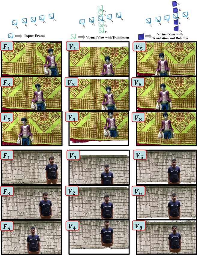
4.2. Novel View VIdeo Synthesis
We evaluate our Novel View video Synthesis on our own video clips that mostly
have a close object to obtain a large movement of an object along with the change of View.
Figure 17 shows the results of our Novel view video synthesis where F1 , F2 , F4 and F5
are the few frames of input video. We create a virtual camera near the path of the input
frame giving a translation along the direction of perpendicular to the camera movement.
In Figure 17, V1 , V2 , V3 and V4 are the virtual camera created from near input frame F3
having only translation along y-direction. V1 and V2 are translated in positive direction
where V4 and V5 are translated in negative direction. The result of virtual view V1 , V2
and V4 of our method shows that closer object movement is bigger than the farther object
rather than the shifting the image along with the change of camera movement. V5 , V6 , V7 ,
and V8 are the virtual view cameras that are created with translation and rotation from F3 .
The novel view result of V5 , V6 and V8 are shown in Figure 17.
In our NVS experiment, we create virtual views V9 and V10 giving translation along
z-axis toward the scene which is demonstrated in Figure 18. Here, virtual view V10 is
created in front of the foreground object and V9 is created behind the object. The novel view
result for V10 shows that the background near the foreground object is occluded because
of the view angle of the camera. This ensures that our method can produce a close view
of a scene rather than zoom-in the original view. The result of V9 is created behind the
foreground object from where the only background of the scene can be observed. In this
case, our NDD scores successfully collect background and avoid foreground points because
the ray segments are positioned behind the foreground object.
It is very difficult to provide an objective evaluation of our novel view video synthesis
method because we do not have the ground truth of novel view. Thus, to provide an objec-
tive evaluation, we consider any view of input video as novel view and inpaint the novel
view without using that particular target view in our inpainting process. To calculate Peak
signal-to-noise ratio (PSNR) and Structural Similarity Index Measure (SSIM), we collect 50
inpainted views and their respective original views from two video clips. Our inpainting
method got an average PSNR 21.82 and SSIM 0.71. As our result have unpainted region
in the border. So we exclude 15 pixel from the border in our PSNR and SSIM calculation.
A comparison between inpainted view and original view are shown in Figure 19.
Our NVVS depends on the extracted depth and the depth is created using photo-
consistency over the epipolar lines of neighboring frame which lie on the direction of
camera movement. Even though our method of depth extraction is not robust to the
uniform color area, our NVVS method can render better results near the path of the input
video. If the wrong depth is calculated in one reference frame, our refining method can
ignore that point considering the color redundancy of the collected set of potential points.
In the case of rendering a novel view video having a bigger distance from the path of
camera movement, our method highly depends on the depth accuracy. These resultsAppl. Sci. 2021, 11, 671 19 of 22
show that our proposed inpainting method using NDD can be generalized for both object
removal and Novel view video synthesis.
(a) (b) (c)
Figure 17. Novel view synthesized video result where first column (a) is the input video sequence, second column (b) is the
synthesized result of translated view along y direction , third column (c) is the synthesized result of translated view along y
direction with rotation.Appl. Sci. 2021, 11, 671 20 of 22
Figure 18. Novel view video synthesis result of virtual camera moving toward the scene of video
and V9 virtual camera produces the scene behind the foreground.
Figure 19. Comparison between original view and synthesized view of our method.Appl. Sci. 2021, 11, 671 21 of 22
5. Conclusions
In this paper, we propose a robust video inpainting method. We calculate a normalized
difference of observed depth and 3D distance over the video frames and find the potential
qualified points to fill the missing region. Our method can fill the missing region by
inpainting the background to remove an object from the video and also generate a totally
novel view video from the input video. Experiments on both public and our own video data
and comparison to state-of-the-art methods show promising video inpainting performance
over diverse challenging conditions to remove foreground objects. For a generalization
of our proposed inpainting method, we also perform Novel View Video synthesis, which
shows encouraging results. However, inappropriate input of depth map and camera
translation matrix estimation can be a cause of poor performance of our inpainting method.
Author Contributions: Conceptualization, A.S. and S.L.; methodology, A.S. and S.L.; software, A.S.;
validation, S.L.; data curation, A.S.; writing—original draft preparation, A.S.; writing—review and
editing, S.L.; visualization, A.S.; supervision, S.L.; project administration, S.L. All authors have read
and agreed to the published version of the manuscript.
Funding: This research received no external funding.
Institutional Review Board Statement: Not applicable.
Informed Consent Statement: Not applicable.
Conflicts of Interest: The authors declare no conflict of interest.
References
1. Criminisi, A.; Pérez, P.; Toyama, K. Region filling and object removal by exemplar-based image inpainting. IEEE Trans. Image
Process. 2004, 13, 1200–1212. [CrossRef] [PubMed]
2. Buyssens, P.; Daisy, M.; Tschumperlé, D.; Lézoray, O. Exemplar-based inpainting: Technical review and new heuristics for better
geometric reconstructions. IEEE Trans. Image Process. 2015, 24, 1809–1824. [CrossRef] [PubMed]
3. Barnes, C.; Shechtman, E.; Finkelstein, A.; Goldman, D.B. PatchMatch: A randomized correspondence algorithm for structural
image editing. ACM Trans. Graph. 2009, 28, 24. [CrossRef]
4. Shih, T.K.; Tang, N.C.; Hwang, J.N. Exemplar-based video inpainting without ghost shadow artifacts by maintaining temporal
continuity. IEEE Trans. Circuits Syst. Video Technol. 2009, 19, 347–360. [CrossRef]
5. Patwardhan, K.A.; Sapiro, G.; Bertalmío, M. Video inpainting under constrained camera motion. IEEE Trans. Image Process. 2007,
16, 545–553. [CrossRef] [PubMed]
6. Shih, T.K.; Tan, N.C.; Tsai, J.C.; Zhong, H.Y. Video falsifying by motion interpolation and inpainting. In Proceedings of the IEEE
Conference on Computer Vision and Pattern Recognition, Anchorage, AK, USA, 23–28 June 2008; pp. 1–8.
7. Wexler, Y.; Shechtman, E.; Irani, M. Space-time completion of video. IEEE Trans. Pattern Anal. Mach. Intell. 2007, 29, 463–476.
[CrossRef] [PubMed]
8. Newson, A.; Almansa, A.; Fradet, M.; Gousseau, Y.; Pérez, P. Video inpainting of complex scenes. SIAM J. Imaging Sci. 2014,
7, 1993–2019. [CrossRef]
9. Lin, W.Y.; Liu, S.; Matsushita, Y.; Ng, T.T.; Cheong, L.F. Smoothly varying affine stitching. In Proceedings of the IEEE Conference
on Computer Vision and Pattern Recognition (CVPR), Providence, RI, USA, 20–25 June 2011; pp. 345–352.
10. Granados, M.; Kim, K.I.; Tompkin, J.; Kautz, J.; Theobalt, C. Background inpainting for videos with dynamic objects and a
free-moving camera. In Proceedings of the European Conference on Computer Vision, Florence, Italy, 7–13 October 2012; Springer:
Berlin/Heidelberg, Germany, 2012; pp. 682–695.
11. Liu, S.; Yuan, L.; Tan, P.; Sun, J. Bundled camera paths for video stabilization. ACM Trans. Graph. 2013, 32, 78. [CrossRef]
12. Ebdelli, M.; Le Meur, O.; Guillemot, C. Video inpainting with short-term windows: Application to object removal and error
concealment. IEEE Trans. Image Process. 2015, 24, 3034–3047. [CrossRef] [PubMed]
13. Bhat, P.; Zitnick, C.L.; Snavely, N.; Agarwala, A.; Agrawala, M.; Cohen, M.; Curless, B.; Kang, S.B. Using photographs to enhance
videos of a static scene. In Proceedings of the 18th Eurographics Conference on Rendering Techniques, EGSR’07, Aire-la-Ville,
Switzerland, 25 June 2007; pp. 327–338. [CrossRef]
14. Klose, F.; Wang, O.; Bazin, J.C.; Magnor, M.; Sorkine-Hornung, A. Sampling based scene-space video processing. ACM Trans.
Graph. 2015, 34, 67. [CrossRef]
15. Seitz, S.M.; Dyer, C.R. Physically-valid view synthesis by image interpolation. In Proceedings of the IEEE Workshop on
Representation of Visual Scenes (In Conjunction with ICCV’95), Cambridge, MA, USA, 24 June 1995; pp. 18–25.
16. Chen, S.E.; Williams, L. View interpolation for image synthesis. In Proceedings of the 20th Annual Conference on Computer
Graphics and Interactive Techniques, Anaheim, CA, USA, 2–6 August 1993; pp. 279–288.
17. Adelson, E.H.; Bergen, J.R. The Plenoptic Function and the Elements of Early Vision; MIT Press: Cambridge, MA, USA, 1991.Appl. Sci. 2021, 11, 671 22 of 22
18. McMillan, L.; Bishop, G. Plenoptic modeling: An image-based rendering system. In Proceedings of the 22nd Annual Conference
on Computer Graphics and Interactive Techniques, Los Angeles, CA, USA, 15 September 1995; pp. 39–46.
19. Levoy, M.; Hanrahan, P. Light field rendering. In Proceedings of the 23rd Annual Conference on Computer Graphics and
Interactive Techniques, New Orleans, LA, USA, 4–9 August 1996; pp. 31–42.
20. Scharstein, D. Stereo vision for view synthesis. In Proceedings of the CVPR IEEE Computer Society Conference on Computer
Vision and Pattern Recognition, San Francisco, CA, USA, 18–20 June 1996; pp. 852–858.
21. Furukawa, Y.; Ponce, J. Accurate, dense, and robust multiview stereopsis. IEEE Trans. Pattern Anal. Mach. Intell. 2010,
32, 1362–1376. [CrossRef] [PubMed]
22. Zhou, Z.; Jin, H.; Ma, Y. Plane-based content preserving warps for video stabilization. In Proceedings of the IEEE Conference on
Computer Vision and Pattern Recognition, Portland, OR, USA, 23–28 June 2013; pp. 2299–2306.
23. Penner, E.; Zhang, L. Soft 3D reconstruction for view synthesis. ACM Trans. Graph. 2017, 36, 235. [CrossRef]
24. Siddique, A.; Lee, S. Video inpainting for arbitrary foreground object removal. In Proceedings of the 2018 IEEE Winter Conference
on Applications of Computer Vision (WACV), Lake Tahoe, NV, USA, 12–15 March 2018; pp. 1755–1763.
25. Oh, S.W.; Lee, J.Y.; Sunkavalli, K.; Kim, S.J. Fast video object segmentation by reference-guided mask propagation. In Proceedings
of the 2018 IEEE/CVF Conference on Computer Vision and Pattern Recognition, Salt Lake City, UT, USA, 18–22 June 2018;
pp. 7376–7385.
26. Wu, C. Towards linear-time incremental structure from motion. In Proceedings of the International Conference on 3D Vision,
Seattle, WA, USA, 29 June–1 July 2013; pp. 127–134.
27. Wang, W.; Shen, J.; Porikli, F. Saliency-aware geodesic video object segmentation. In Proceedings of the IEEE Conference on
Computer Vision and Pattern Recognition, Boston, MA, USA, 7–12 June 2015; pp. 3395–3402.
28. Tokmakov, P.; Alahari, K.; Schmid, C. Learning motion patterns in videos. In Proceedings of the IEEE Conference on Computer
Vision and Pattern Recognition, Honolulu, HI, USA, 21–26 July 2017; pp. 3386–3394.You can also read