Multi-Scaler v1.2 LogiCORE IP Product Guide - Vivado Design Suite - Xilinx
←
→
Page content transcription
If your browser does not render page correctly, please read the page content below
Multi-Scaler v1.2

LogiCORE IP Product Guide
Vivado Design Suite

PG325 (v1.2) February 4, 2021
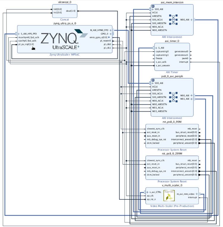
Table of Contents
       Chapter 1: Introduction.............................................................................................. 4
          Features........................................................................................................................................ 4
          IP Facts..........................................................................................................................................5

       Chapter 2: Overview......................................................................................................6
          Navigating Content by Design Process.................................................................................... 6
          Core Overview..............................................................................................................................6
          Feature Summary........................................................................................................................ 7
          Applications..................................................................................................................................7
          Licensing and Ordering.............................................................................................................. 7

       Chapter 3: Product Specification........................................................................... 8
          Standards..................................................................................................................................... 8
          Performance................................................................................................................................ 8
          Resource Use............................................................................................................................... 9
          Port Descriptions.........................................................................................................................9
          Register Space........................................................................................................................... 15

       Chapter 4: Designing with the Core................................................................... 25
          Clocking...................................................................................................................................... 25
          Polyphase Scaling......................................................................................................................25
          System Considerations............................................................................................................. 28

       Chapter 5: Design Flow Steps.................................................................................29
          Customizing and Generating the Core................................................................................... 29
          Constraining the Core...............................................................................................................32
          Simulation.................................................................................................................................. 33
          Synthesis and Implementation................................................................................................33

       Chapter 6: Example Design..................................................................................... 34
          Synthesizable Example Design................................................................................................ 36

PG325 (v1.2) February 4, 2021                                                                                                        www.xilinx.com
                                                                                                      Send Feedback
Multi-Scaler                                                                                                                                      2
Appendix A: Verification, Compliance, and Interoperability...............44

       Appendix B: Upgrading............................................................................................. 45
          Upgrading in the Vivado Design Suite....................................................................................45

       Appendix C: Application Software Development....................................... 46
          Building the BSP........................................................................................................................ 46
          Modes of Operation.................................................................................................................. 46
          Usage.......................................................................................................................................... 47

       Appendix D: Debugging............................................................................................ 49
          Finding Help on Xilinx.com...................................................................................................... 49
          Debug Tools............................................................................................................................... 50
          Hardware Debug....................................................................................................................... 51

       Appendix E: Additional Resources and Legal Notices..............................52
          Xilinx Resources.........................................................................................................................52
          Documentation Navigator and Design Hubs.........................................................................52
          References..................................................................................................................................52
          Revision History......................................................................................................................... 53
          Please Read: Important Legal Notices................................................................................... 54

PG325 (v1.2) February 4, 2021                                                                                                       www.xilinx.com
                                                                                                      Send Feedback
Multi-Scaler                                                                                                                                     3
Chapter 1: Introduction

                                                                                       Chapter 1

Introduction
       The Xilinx® LogiCORE™ IP Video Multi-Scaler core provides a video processing block, that
       converts the input color images of one size to output color images of a different size. It is a
       memory interface based IP core which supports the generation of up to eight scaled outputs.
       This highly configurable IP core supports in-system programmability through a comprehensive
       register interface to control it. A comprehensive set of interrupt status bits are provided for
       monitoring the processor.

Features
       • Memory mapped AXI4 Interface
       • Supports maximum eight outputs
       • Supports spatial resolutions from 64 × 64 up to 8192 × 4320
       • Supports one, two, or four pixel-width
       • Supports RGB, YUV 444, YUV 422, YUV 420
       • Supports 8-bit and 10-bit per color component on memory interface
       • Supports semi-planar memory formats next to packed memory formats
       • Dynamically configurable source and destination buffer addresses
       • Supports 6, 8, 10, and 12 taps in both H and V domains
       • Supports 64 phases
       • Supports 8k 30 fps depending on the device family
       • Supports 32-bit and 64-bit DDR memory address access

PG325 (v1.2) February 4, 2021                                                             www.xilinx.com
                                                                      Send Feedback
Multi-Scaler                                                                                           4
Chapter 1: Introduction
IP Facts
LogiCORE™ IP Facts Table
Core Specifics
Supported Device Family1 Versal™ ACAP, UltraScale+™, UltraScale™, 7 Series FPGAs, Zynq®-7000 SoC
Supported User Interfaces AXI Master Lite, AXI4-Lite
Resources Performance and Resource Use web page
Provided with Core
Design Files Not Provided
Example Design Verilog
Test Bench Not Provided
Constraints File Xilinx Design Constraints (XDC)
Simulation Model Encrypted RTL
Supported S/W Driver2 Standalone
Linux V4L2 MEM2MEM
Tested Design Flows3
Design Entry Vivado® Design Suite
Simulation For supported simulators, see the Xilinx Design Tools: Release Notes Guide.
Synthesis Vivado Synthesis
Support
Release Notes and Known Issues Master Answer Record: 70292
All Vivado IP Change Logs Master Vivado IP Change Logs: 72775
Xilinx Support web page
Notes:
1. For a complete list of supported devices, see the Vivado® IP catalog.
2. Standalone driver details can be found in the software development kit (Vitis) directory (/Vitis/
/data/embeddedsw/doc/xilinx_drivers.htm). Linux OS and driver support information is available from the
Xilinx Wiki page.
3. For the supported versions of third-party tools, see the Xilinx Design Tools: Release Notes Guide.
PG325 (v1.2) February 4, 2021 www.xilinx.com
Send Feedback
Multi-Scaler 5Chapter 2: Overview
Chapter 2
Overview
Navigating Content by Design Process
Xilinx® documentation is organized around a set of standard design processes to help you find
relevant content for your current development task. This document covers the following design
processes:
• Hardware, IP, and Platform Development: Creating the PL IP blocks for the hardware
platform, creating PL kernels, subsystem functional simulation, and evaluating the Vivado®
timing, resource use, and power closure. Also involves developing the hardware platform for
system integration. Topics in this document that apply to this design process include:
• Port Descriptions
• Clocking
• Customizing and Generating the Core
• Chapter 6: Example Design
Core Overview
The Multi-Scaler core generates up to eight scaled output images from a single or multiple (up to
eight) external video and/or graphics sources. Video scaling is the process of converting an input
color image of dimensions Xin pixels by Yin lines to an output color image of dimensions Xout
pixels by Yout lines. Multi-Scaler IP reads the input images from the source buffer adresses and
writes the scaled output images to the destination buffer addresses. All the source and
destination buffer addresses of the IP can be dynamically changed.
PG325 (v1.2) February 4, 2021 www.xilinx.com
Send Feedback
Multi-Scaler 6Chapter 2: Overview
Feature Summary
The Video Multi-Scaler is a configurable IP core that generates up to eight scaled images. All the
outputs and the inputs are memory mapped AXI4 interface based. Scaling is performed in both
the H and V domains on per output basis. Video Multi-Scaler IP has built-in color space
conversion between RGB and YUV 4:4:4 and chroma re-sampling between YUV 4:4:4, YUV
4:2:2, and YUV 4:2:0. Video Multi-Scaler IP has support for resolutions from 64 × 64 to 7,680 ×
4,320 with up to three color components, each of 8 or 10 bits. The video Multi-Scaler IP reads
the image from the source buffer address, scales it in both the H and V domains and writes it to
the destination buffer address. The video Multi-Scaler sends the interrupt after generating all the
outputs. All the outputs are generated one after the other sequentially. The source buffer and the
destination buffer addresses can be dynamically changed so that the user can point to any buffer
address while the IP is running.
Note: Multi-Scaler supports only resolution scaling, it does not support frame rate conversion.
Applications
The Multi-Scaler core is used in applications such as video servers, data centers, and video
conferencing.
Licensing and Ordering
This Xilinx® LogiCORE™ IP module is provided at no additional cost with the Xilinx Vivado®
Design Suite under the terms of the Xilinx End User License.
Note: To verify that you need a license, check the License column of the IP Catalog. Included means that a
license is included with the Vivado® Design Suite; Purchase means that you have to purchase a license to
use the core.
Information about other Xilinx® LogiCORE™ IP modules is available at the Xilinx Intellectual
Property page. For information about pricing and availability of other Xilinx LogiCORE IP modules
and tools, contact your local Xilinx sales representative.
PG325 (v1.2) February 4, 2021 www.xilinx.com
Send Feedback
Multi-Scaler 7Chapter 3: Product Specification
Chapter 3
Product Specification
Standards
The Video Multi-Scaler IP is compliant with the AXI4-Lite interconnect and memory mapped
AXI4 interface standards. For additional information, see the Video IP: AXI Feature Adoption
section of Vivado Design Suite: AXI Reference Guide (UG1037).
Performance
The following sections detail the performance characteristics of the Video Multi-Scaler IP.
Maximum Frequencies
The following are typical clock frequencies for the target devices:
• Virtex®-7 and Virtex® UltraScale™ devices with –2 speed grade or higher: 300 MHz
• UltraScale+™ device with –1 speed grade or higher: 300 MHz
• Kintex®-7 and Kintex® UltraScale™ devices with –2 speed grade or higher: 300 MHz
• Artix®-7 devices with –2 speed grade or higher: 150 MHz
• Versal™ ACAP devices with –1 speed grade or higher: 300 MHz
The maximum achievable clock frequency can vary. The maximum achievable clock frequency
and all resource counts can be affected by other tool options, additional logic in the device, using
a different version of Xilinx® tools, and other factors.
PG325 (v1.2) February 4, 2021 www.xilinx.com
Send Feedback
Multi-Scaler 8Chapter 3: Product Specification
Resource Use
For full details about performance and resource use, visit the Performance and Resource Use web
page.
Port Descriptions
The core interfaces are shown in the following figure.
Figure 1: Core Ports
Common Interface Signals
Table 1: Common Interface Signals
Signal Name I/O Width Description
ap_clk I 1 Video core clock
ap_rst_n I 1 Video core active-Low reset
interrupt O 1 Interrupt Request Pin
The ap_clk and ap_rst_n signals are shared between the core, memory mapped AXI4 data
interfaces, and the AXI4-Lite control interface.
• ap_clk: The memory mapped AXI4, and AXI4-Lite interfaces must be synchronous to the core
clock signal ap_clk. All memory mapped AXI4 interface input signals and AXI4-Lite control
interface input signals are sampled on the rising edge of ap_clk.
• ap_rst_n: The ap_rst_n pin is an active-Low, synchronous reset input pertaining to both
AXI4-Lite and memory mapped AXI4 interfaces. When ap_rst_n is set to 0, the core resets
at the next rising edge of ap_clk.
PG325 (v1.2) February 4, 2021 www.xilinx.com
Send Feedback
Multi-Scaler 9Chapter 3: Product Specification
• interrupt: The interrupt status output bus can be integrated with an external interrupt
controller that has independent interrupt enable/mask, interrupt clear, and interrupt status
registers that allow interrupt aggregation to the system processor.
AXI4-Lite Control Interface
The AXI4-Lite interface allows you to dynamically control parameters within the core. The
configuration can be accomplished using an AXI4-Lite master state machine, an embedded Arm®,
or soft system processor such as MicroBlaze™. The Video Multi-Scaler can be controlled through
the AXI4-Lite interface by using functions provided by the driver in the Vitis. Another method is
performing read and write transactions to the register space but should only be used when the
first method is not available. The following table shows the AXI4-Lite control interface signals.
This interface runs at the ap_clk clock.
Table 2: AXI4-Lite Control Interface Signals
Signal Name I/O Width Description
s_axi_ctrl_aresetn I 1 Reset
s_axi_ctrl_aclk I 1 Clock
s_axi_ctrl_awaddr I 18 Write Address
s_axi_ctrl_awprot I 3 Write Address Protection
s_axi_ctrl_awvalid I 1 Write Address Valid
s_axi_ctrl_awready O 1 Write Address Ready
s_axi_ctrl_wdata I 32 Write Data
s_axi_ctrl_wstrb I 4 Write Data Strobe
s_axi_ctrl_wvalid I 1 Write Data Valid
s_axi_ctrl_wready O 1 Write Data Ready
s_axi_ctr_bresp O 2 Write Response
s_axi_ctrl_bvalid O 1 Write Response Valid
s_axi_ctrl_bready I 1 Write Response Ready
s_axi_ctrl_araddr I 18 Read Address
s_axi_ctrl_arprot I 3 Read Address Protection
s_axi_ctrl_arvalid I 1 Read Address Valid
s_axi_ctrl_aready O 1 Read Address Ready
s_axi_ctrl_rdata O 32 Read Data
s_axi_ctrl_rresp O 2 Read Data Response
s_axi_ctrl_rvalid O 1 Read Data Valid
s_axi_ctrl_rready 1 1 Read Data Ready
PG325 (v1.2) February 4, 2021 www.xilinx.com
Send Feedback
Multi-Scaler 10Chapter 3: Product Specification
Memory Mapped AXI4 Interface
There is a memory mapped AXI4 interface named m_axi_mm_video. The memory mapped
AXI4 interface runs on the ap_clk clock domain. The signals follow the specification as defined
in Vivado Design Suite: AXI Reference Guide (UG1037).
Table 3: Pixel Formats Supported by the Memory based Multi-Scaler IP Core
Bits Per
Video Format Description Bytes per Pixel
Component
RGBX8 Packed RGB 8 4 bytes per pixel
RGB8 Packed RGB 8 3 bytes per pixel
BGRX8 Packed BGR 8 4 bytes per pixel
BGR8 Packed BGR 8 3 bytes per pixel
YUVX8 Packed YUV 4:4:4 8 4 bytes per pixel
YUV8 Packed YUV 4:4:4 8 3 bytes per pixel
YUYV8 Packed YUV 4:2:2 8 2 bytes per pixel
UYVY8 Packed YUV 4:2:2 8 2 bytes per pixel
Y_UV8 Semi-planar YUV 4:2:2 8 1 byte per pixel per plane
Y_UV8_420 Semi-planar YUV 4:2:0 8 1 byte per pixel per plane
Y8 Packed luma only 8 1 byte per pixel
RGBX10 Packed RGB 10 4 bytes per pixel
YUVX10 Packed YUV 4:4:4 10 4 bytes per pixel
Y_UV10 Semi-planar YUV 4:2:2 10 4 bytes per 3 pixels per plane
Y_UV10_420 Semi-planar YUV 4:2:0 10 4 bytes per 3 pixels per plane
Y10 Packed luma only 10 4 bytes per 3 pixel
Note: See Video Frame Buffer Read and Video Frame Buffer Write LogiCORE IP Product Guide (PG278) for
information on how these video formats cross reference to software formats.
The following tables explain the expected pixel mappings in memory for each of the mentioned
listed formats.
RGBX8
Packed RGB, 8 bits per component. Every RGB pixel in memory is represented with 32 bits, as
shown in the following table. The images need be stored in memory in raster order, that is top-
left pixel first and the bottom-right pixel last. Bits[31:24] do not contain pixel information.
Table 4: RGBX8 Pixel Format
31:24 23:16 15:8 7:0
X B G R
YUVX8
PG325 (v1.2) February 4, 2021 www.xilinx.com
Send Feedback
Multi-Scaler 11Chapter 3: Product Specification
Packed YUV 4:4:4, 8 bits per component. Every YUV 4:4:4 pixel in memory is represented with
32 bits, as shown in the following table. Bits[31:24] do not contain pixel information.
Table 5: YUVX8 Pixel Format
31:24 23:16 15:8 7:0
X V U Y
YUYV8
Packed YUV 4:2:2, 8 bits per component. Every two YUY 4:2:2 pixels in memory are represented
with 32 bits, as shown in the following table.
Table 6: YUYV8 Pixel Format
31:24 23:16 15:8 7:0
V0 Y1 U0 Y0
RGBX10
Packed RGB, 10 bits per component. Every RGB pixel is represented with 32 bits, as shown in the
following. Bits[31:30] do not contain any pixel information.
Table 7: RGBX10 Pixel Format
31:30 29:20 19:10 9:0
X B G R
YUVX10
Packed YUV 4:4:4, 10 bits per component. Every YUV 4:4:4 pixel is represented with 32 bits, as
shown in the following table. Bits[31:30] do not contain any pixel information.
Table 8: YUVX10 Pixel Format
31:30 29:20 19:10 9:0
X V U Y
Y_UV8
Semi-planar YUV 4:2:2 with 8 bits per component. Y and UV stored in separate planes as shown
in the following table. The UV plane is assumed to have an offset of stride × height bytes from
the Y plane buffer address.
PG325 (v1.2) February 4, 2021 www.xilinx.com
Send Feedback
Multi-Scaler 12Chapter 3: Product Specification
Table 9: Y_UV8 Pixel Format
31:24 23:16 15:8 7:0
Y Y3 Y2 Y1 Y0
UV V2 U2 V0 U0
Y_UV8_420
Semi-planar YUV 4:2:0 with 8 bits per component. Y and UV stored in separate planes as shown
in the following table. The UV plane is assumed to have an offset of stride × height bytes from
the Y plane buffer address.
Table 10: Y_UV8_420 Pixel Format
31:24 23:16 15:8 7:0
Y3 Y2 Y1 Y0
RGB8
Packed RGB, 8 bits per component. Every RGB pixel in memory is represented with 24 bits, as
shown in the following table. The images need be stored in memory in raster order, that is, top-
left pixel first, bottom-right pixel last.
Table 11: RGB8 Pixel Format
23:16 15:8 7:0
B G R
YUV8
Packed YUV 4:4:4, 8 bits per component. Every YUV 4:4:4 pixel in memory is represented with
24 bits, as shown in the following table. The images need be stored in memory in raster order,
that is, top-left pixel first, bottom-right pixel last.
Table 12: YUV8 Pixel Format
23:16 15:8 7:0
V U Y
Y_UV10
Semi-planar YUV 4:2:2 with 10 bits per component. Every 3 pixels is represented with 32 bits.
Bits[31:30] do not contain any pixel information. Y and UV stored in separate planes as shown in
the following table. The UV plane is assumed to have an offset of stride x height bytes from the Y
plane buffer address.
PG325 (v1.2) February 4, 2021 www.xilinx.com
Send Feedback
Multi-Scaler 13Chapter 3: Product Specification
Table 13: Y_UV10 Pixel Format
63:62 61:52 51:42 41:32 31:30 29:20 19:10 9:0
Y X Y5 Y4 Y3 X Y2 Y1 Y0
UV X V4 U4 V2 X U2 V0 U0
Y_UV10_420
Semi-planar YUV 4:2:0 with 10 bits per component. Every 3 pixels is represented with 32 bits.
Bits[31:30] do not contain any pixel information. Y and UV stored in separate planes as shown in
the following table. The UV plane is assumed to have an offset of stride x height bytes from the Y
plane buffer address.
Table 14: Y_UV10_420 Pixel Format
63:62 61:52 51:42 41:32 31:30 29:20 19:10 9:0
Y X Y5 Y4 Y3 X Y2 Y1 Y0
UV X V8 U8 v4 X U4 V0 U0
Y8
Packed Luma-Only, 8 bits per component. Every luma-only pixel in memory is represented with 8
bits, as shown in the following table. The images need be stored in memory in raster order, that
is, top-left pixel first, bottom-right pixel last.
Table 15: Y8 Pixel Format
7:0
Y
Y10
Packed Luma-Only, 10 bits per component. Every three luma-only pixels in memory is
represented with 32 bits, as shown in the following table. The images need be stored in memory
in raster order, that is, top-left pixel first, bottom-right pixel last. Bits[31:30] do not contain pixel
information.
Table 16: Y10 Pixel Format
31:30 29:20 19:10 9:0
X Y2 Y1 Y0
BGRX8
PG325 (v1.2) February 4, 2021 www.xilinx.com
Send Feedback
Multi-Scaler 14Chapter 3: Product Specification
Packed BGR, 8 bits per component. Every BGR pixel in memory is represented with 32 bits, as
shown in the following table. The images need be stored in memory in raster order, that is, top-
left pixel first, bottom-right pixel last. Bits[31:24] do not contain pixel information.
Table 17: BGRX8 Pixel Format
31:24 23:16 15:8 7:0
X R G B
UYVY8
Packed YUV 4:2:2, 8 bits per component. Every two YUV 4:2:2 pixels in memory are represented
with 32 bits, as shown in the following table.
Table 18: UYVY8 Pixel Format
31:24 23:16 15:8 7:0
Y1 V0 Y0 U0
BGR8
Packed BGR, 8 bits per component. Every BGR pixel in memory is represented with 24 bits, as
shown in the following table. The images need to be stored in memory in raster order, that is,
top-left pixel first, bottom-right pixel last.
Table 19: BGR8 Pixel Format
23:16 15:8 7:0
B G R
Register Space
The Video Multi-Scaler IP has specific registers that allow you to control the operation of the
core. All registers have an initial value of 0.
The following table provides a detailed description of all the registers that apply globally to the
IP.
PG325 (v1.2) February 4, 2021 www.xilinx.com
Send Feedback
Multi-Scaler 15Chapter 3: Product Specification
Table 20: Register Address Space
Address (hex) Access
Register Name Register Description
BASEADDR+ Type
0x0000 Control Signals R/W/COH1 Bit[0] = ap_start
R/W/COR2 Bit[1] = ap_done
R/W Bit[2] = ap_idle
Bit[3] = ap_ready
Bit[7] = auto_restart
Others = Reserved
0x00004 Global Interrupt Enable R/W Bit[0] = Global interrupt enable
Others = Reserved
0x00008 IP Interrupt Enable R/W Bit[0] = Channel 0 (ap_done)
Bit[1] = Channel 1 (ap_ready)
Others = reserved
0x0000C IP Interrupt Status Register R/TOW3 Bit[0] = Channel 0 (ap_done)
Bit[1] = Channel 1 (ap_ready)
Others = Reserved
0x00010 HwReg_num_outs R/W Bit[7] to Bit[0] = HwReg_num_outs[7:0]
Others = Reserved
0x00100 HwReg_WidthIn_0 R/W Bit[15] to Bit[0] = HwReg_WidthIn_0[15:0]
Others = Reserved
0x00108 HwReg_WidthOut_0 R/W Bit[15] to Bit[0] = HwReg_ WidthOut_0[15:0]
Others = reserved
0x00110 HwReg_ HeightIn_0 R/W Bit[15] to Bit[0] = HwReg_HeightIn_0[15:0]
Others = Reserved
0x00118 HwReg_HeightOut_0 R/W Bit[15] to Bit[0] = HwReg_HeightOut_0[15:0]
Others = Reserved
0x00120 HwReg_LineRate_0 R/W Bit[31] to Bit[0] = HwReg_LineRate_0[31:0]
0x00128 HwReg_PixelRate_0 R/W Bit[31] to Bit[0] = HwReg_PixelRate_0[31:0]
0x00130 HwReg_InPixelFmt_0 R/W Bit[7] to Bit[0] = HwReg_InPixelFmt_0[7:0]
Others = Reserved
0x00138 HwReg_OutPixelFmt_0 R/W Bit[7] to Bit[0] = HwReg_OutPixelFmt_0[7:0]
Others = Reserved
0x00150 HwReg_InStride_0 R/W Bit[15] to Bit[0] = HwReg_InStride_0[15:0]
Others = Reserved
0x00158 HwReg_OutStride_0 R/W Bit[15] to Bit[0] = HwReg_OutStride_0[15:0]
Others = Reserved
0x00160 HwReg_srcImgBuf0_0_V R/W Bit[31] to Bit[0] = HwReg_srcImgBuf0_0_V[31:0]
0x00170 HwReg_srcImgBuf1_0_V R/W Bit[31] to Bit[0] = HwReg_srcImgBuf1_0_V[31:0]
0x00190 HwReg_dstImgBuf0_0_V R/W Bit[31] to Bit[0] = HwReg_dstImgBuf0_0_V[31:0]
0x00200 HwReg_dstImgBuf1_0_V R/W Bit[31] to Bit[0] = HwReg_dstImgBuf1_0_V[31:0]
PG325 (v1.2) February 4, 2021 www.xilinx.com
Send Feedback
Multi-Scaler 16Chapter 3: Product Specification
Table 20: Register Address Space (cont'd)
Address (hex) Access
Register Name Register Description
BASEADDR+ Type
0x00300 HwReg_WidthIn_1 R/W Bit[15] to Bit[0] = HwReg_WidthIn_1[15:0]
Others = Reserved
0x00308 HwReg_WidthOut_1 R/W Bit[15] to Bit[0] = HwReg_ WidthOut_1[15:0]
Others = reserved
0x00310 HwReg_ HeightIn_1 R/W Bit[15] to Bit[0] = HwReg_HeightIn_1[15:0]
Others = Reserved
0x00318 HwReg_HeightOut_1 R/W Bit[15] to Bit[0] = HwReg_HeightOut_1[15:0]
Others = Reserved
0x00320 HwReg_LineRate_1 R/W Bit[31] to Bit[0] = HwReg_LineRate_1[31:0]
0x00328 HwReg_PixelRate_1 R/W Bit[31] to Bit[0] = HwReg_PixelRate_1[31:0]
0x00330 HwReg_InPixelFmt_1 R/W Bit[7] to Bit[0] = HwReg_InPixelFmt_1[7:0]
Others = Reserved
0x00338 HwReg_OutPixelFmt_1 R/W Bit[7] to Bit[0] = HwReg_OutPixelFmt_1[7:0]
Others = Reserved
0x00350 HwReg_InStride_1 R/W Bit[15] to Bit[0] = HwReg_InStride_1[15:0]
Others = Reserved
0x00358 HwReg_OutStride_1 R/W Bit[15] to Bit[0] = HwReg_OutStride_1[15:0]
Others = Reserved
0x00360 HwReg_srcImgBuf0_1_V R/W Bit[31] to Bit[0] = HwReg_srcImgBuf0_1_V[31:0]
0x00370 HwReg_srcImgBuf1_1_V R/W Bit[31] to Bit[0] = HwReg_srcImgBuf1_1_V[31:0]
0x00390 HwReg_dstImgBuf0_1_V R/W Bit[31] to Bit[0] = HwReg_dstImgBuf0_1_V[31:0]
0x00400 HwReg_dstImgBuf1_1_V R/W Bit[31] to Bit[0] = HwReg_dstImgBuf1_1_V[31:0]
0x00500 HwReg_WidthIn_2 R/W Bit[15] to Bit[0] = HwReg_WidthIn_2[15:0]
Others = Reserved
0x00508 HwReg_WidthOut_2 R/W Bit[15] to Bit[0] = HwReg_ WidthOut_2[15:0]
Others = reserved
0x00510 HwReg_ HeightIn_2 R/W Bit[15] to Bit[0] = HwReg_HeightIn_2[15:0]
Others = Reserved
0x00518 HwReg_HeightOut_2 R/W Bit[15] to Bit[0] = HwReg_HeightOut_2[15:0]
Others = Reserved
0x00520 HwReg_LineRate_2 R/W Bit[31] to Bit[0] = HwReg_LineRate_2[31:0]
0x00528 HwReg_PixelRate_2 R/W Bit[31] to Bit[0] = HwReg_PixelRate_2[31:0]
0x00530 HwReg_InPixelFmt_2 R/W Bit[7] to Bit[0] = HwReg_InPixelFmt_2[7:0]
Others = Reserved
0x00538 HwReg_OutPixelFmt_2 R/W Bit[7] to Bit[0] = HwReg_OutPixelFmt_2[7:0]
Others = Reserved
0x00550 HwReg_InStride_2 R/W Bit[15] to Bit[0] = HwReg_InStride_2[15:0]
Others = Reserved
PG325 (v1.2) February 4, 2021 www.xilinx.com
Send Feedback
Multi-Scaler 17Chapter 3: Product Specification
Table 20: Register Address Space (cont'd)
Address (hex) Access
Register Name Register Description
BASEADDR+ Type
0x00558 HwReg_OutStride_2 R/W Bit[15] to Bit[0] = HwReg_OutStride_2[15:0]
Others = Reserved
0x00560 HwReg_srcImgBuf0_2_V R/W Bit[31] to Bit[0] = HwReg_srcImgBuf0_2_V[31:0]
0x00570 HwReg_srcImgBuf1_2_V R/W Bit[31] to Bit[0] = HwReg_srcImgBuf1_2_V[31:0]
0x00590 HwReg_dstImgBuf0_2_V R/W Bit[31] to Bit[0] = HwReg_dstImgBuf0_2_V[31:0]
0x00600 HwReg_dstImgBuf1_2_V R/W Bit[31] to Bit[0] = HwReg_dstImgBuf1_2_V[31:0]
0x00700 HwReg_WidthIn_3 R/W Bit[15] to Bit[0] = HwReg_WidthIn_3[15:0]
Others = Reserved
0x00708 HwReg_WidthOut_3 R/W Bit[15] to Bit[0] = HwReg_ WidthOut_3[15:0]
Others = reserved
0x00710 HwReg_ HeightIn_3 R/W Bit[15] to Bit[0] = HwReg_HeightIn_3[15:0]
Others = Reserved
0x00718 HwReg_HeightOut_3 R/W Bit[15] to Bit[0] = HwReg_HeightOut_3[15:0]
Others = Reserved
0x00720 HwReg_LineRate_3 R/W Bit[31] to Bit[0] = HwReg_LineRate_3[31:0]
0x00728 HwReg_PixelRate_3 R/W Bit[31] to Bit[0] = HwReg_PixelRate_3[31:0]
0x00730 HwReg_InPixelFmt_3 R/W Bit[7] to Bit[0] = HwReg_InPixelFmt_3[7:0]
Others = Reserved
0x00738 HwReg_OutPixelFmt_3 R/W Bit[7] to Bit[0] = HwReg_OutPixelFmt_3[7:0]
Others = Reserved
0x00750 HwReg_InStride_3 R/W Bit[15] to Bit[0] = HwReg_InStride_3[15:0]
Others = Reserved
0x00758 HwReg_OutStride_3 R/W Bit[15] to Bit[0] = HwReg_OutStride_3[15:0]
Others = Reserved
0x00760 HwReg_srcImgBuf0_3_V R/W Bit[31] to Bit[0] = HwReg_srcImgBuf0_3_V[31:0]
0x00770 HwReg_srcImgBuf1_3_V R/W Bit[31] to Bit[0] = HwReg_srcImgBuf1_3_V[31:0]
0x00790 HwReg_dstImgBuf0_3_V R/W Bit[31] to Bit[0] = HwReg_dstImgBuf0_3_V[31:0]
0x00800 HwReg_dstImgBuf1_3_V R/W Bit[31] to Bit[0] = HwReg_dstImgBuf1_3_V[31:0]
0x00900 HwReg_WidthIn_4 R/W Bit[15] to Bit[0] = HwReg_WidthIn_4[15:0]
Others = Reserved
0x00908 HwReg_WidthOut_4 R/W Bit[15] to Bit[0] = HwReg_ WidthOut_4[15:0]
Others = reserved
0x00910 HwReg_ HeightIn_4 R/W Bit[15] to Bit[0] = HwReg_HeightIn_4[15:0]
Others = Reserved
0x00918 HwReg_HeightOut_4 R/W Bit[15] to Bit[0] = HwReg_HeightOut_4[15:0]
Others = Reserved
0x00920 HwReg_LineRate_4 R/W Bit[31] to Bit[0] = HwReg_LineRate_4[31:0]
0x00928 HwReg_PixelRate_4 R/W Bit[31] to Bit[0] = HwReg_PixelRate_4[31:0]
PG325 (v1.2) February 4, 2021 www.xilinx.com
Send Feedback
Multi-Scaler 18Chapter 3: Product Specification
Table 20: Register Address Space (cont'd)
Address (hex) Access
Register Name Register Description
BASEADDR+ Type
0x00930 HwReg_InPixelFmt_4 R/W Bit[7] to Bit[0] = HwReg_InPixelFmt_4[7:0]
Others = Reserved
0x00938 HwReg_OutPixelFmt_4 R/W Bit[7] to Bit[0] = HwReg_OutPixelFmt_4[7:0]
Others = Reserved
0x00950 HwReg_InStride_4 R/W Bit[15] to Bit[0] = HwReg_InStride_4[15:0]
Others = Reserved
0x00958 HwReg_OutStride_4 R/W Bit[15] to Bit[0] = HwReg_OutStride_4[15:0]
Others = Reserved
0x00960 HwReg_srcImgBuf0_4_V R/W Bit[31] to Bit[0] = HwReg_srcImgBuf0_4_V[31:0]
0x00970 HwReg_srcImgBuf1_4_V R/W Bit[31] to Bit[0] = HwReg_srcImgBuf1_4_V[31:0]
0x00990 HwReg_dstImgBuf0_4_V R/W Bit[31] to Bit[0] = HwReg_dstImgBuf0_4_V[31:0]
0x01000 HwReg_dstImgBuf1_4_V R/W Bit[31] to Bit[0] = HwReg_dstImgBuf1_4_V[31:0]
0x01100 HwReg_WidthIn_5 R/W Bit[15] to Bit[0] = HwReg_WidthIn_5[15:0]
Others = Reserved
0x01108 HwReg_WidthOut_5 R/W Bit[15] to Bit[0] = HwReg_ WidthOut_5[15:0]
Others = reserved
0x01110 HwReg_ HeightIn_5 R/W Bit[15] to Bit[0] = HwReg_HeightIn_5[15:0]
Others = Reserved
0x01118 HwReg_HeightOut_5 R/W Bit[15] to Bit[0] = HwReg_HeightOut_5[15:0]
Others = Reserved
0x01120 HwReg_LineRate_5 R/W Bit[31] to Bit[0] = HwReg_LineRate_5[31:0]
0x01128 HwReg_PixelRate_5 R/W Bit[31] to Bit[0] = HwReg_PixelRate_5[31:0]
0x01130 HwReg_InPixelFmt_5 R/W Bit[7] to Bit[0] = HwReg_InPixelFmt_5[7:0]
Others = Reserved
0x01138 HwReg_OutPixelFmt_5 R/W Bit[7] to Bit[0] = HwReg_OutPixelFmt_5[7:0]
Others = Reserved
0x01150 HwReg_InStride_5 R/W Bit[15] to Bit[0] = HwReg_InStride_5[15:0]
Others = Reserved
0x01158 HwReg_OutStride_5 R/W Bit[15] to Bit[0] = HwReg_OutStride_5[15:0]
Others = Reserved
0x01160 HwReg_srcImgBuf0_5_V R/W Bit[31] to Bit[0] = HwReg_srcImgBuf0_5_V[31:0]
0x01170 HwReg_srcImgBuf1_5_V R/W Bit[31] to Bit[0] = HwReg_srcImgBuf1_5_V[31:0]
0x01190 HwReg_dstImgBuf0_5_V R/W Bit[31] to Bit[0] = HwReg_dstImgBuf0_5_V[31:0]
0x01200 HwReg_dstImgBuf1_5_V R/W Bit[31] to Bit[0] = HwReg_dstImgBuf1_5_V[31:0]
0x01300 HwReg_WidthIn_6 R/W Bit[15] to Bit[0] = HwReg_WidthIn_6[15:0]
Others = Reserved
0x01308 HwReg_WidthOut_6 R/W Bit[15] to Bit[0] = HwReg_ WidthOut_6[15:0]
Others = reserved
PG325 (v1.2) February 4, 2021 www.xilinx.com
Send Feedback
Multi-Scaler 19Chapter 3: Product Specification
Table 20: Register Address Space (cont'd)
Address (hex) Access
Register Name Register Description
BASEADDR+ Type
0x01310 HwReg_ HeightIn_6 R/W Bit[15] to Bit[0] = HwReg_HeightIn_6[15:0]
Others = Reserved
0x01318 HwReg_HeightOut_6 R/W Bit[15] to Bit[0] = HwReg_HeightOut_6[15:0]
Others = Reserved
0x01320 HwReg_LineRate_6 R/W Bit[31] to Bit[0] = HwReg_LineRate_6[31:0]
0x01328 HwReg_PixelRate_6 R/W Bit[31] to Bit[0] = HwReg_PixelRate_6[31:0]
0x01330 HwReg_InPixelFmt_6 R/W Bit[7] to Bit[0] = HwReg_InPixelFmt_6[7:0]
Others = Reserved
0x01338 HwReg_OutPixelFmt_6 R/W Bit[7] to Bit[0] = HwReg_OutPixelFmt_6[7:0]
Others = Reserved
0x01350 HwReg_InStride_6 R/W Bit[15] to Bit[0] = HwReg_InStride_6[15:0]
Others = Reserved
0x01358 HwReg_OutStride_6 R/W Bit[15] to Bit[0] = HwReg_OutStride_6[15:0]
Others = Reserved
0x01360 HwReg_srcImgBuf0_6_V R/W Bit[31] to Bit[0] = HwReg_srcImgBuf0_6_V[31:0]
0x01370 HwReg_srcImgBuf1_6_V R/W Bit[31] to Bit[0] = HwReg_srcImgBuf1_6_V[31:0]
0x01390 HwReg_dstImgBuf0_6_V R/W Bit[31] to Bit[0] = HwReg_dstImgBuf0_6_V[31:0]
0x01400 HwReg_dstImgBuf1_6_V R/W Bit[31] to Bit[0] = HwReg_dstImgBuf1_6_V[31:0]
0x01500 HwReg_WidthIn_7 R/W Bit[15] to Bit[0] = HwReg_WidthIn_7[15:0]
Others = Reserved
0x01508 HwReg_WidthOut_7 R/W Bit[15] to Bit[0] = HwReg_ WidthOut_7[15:0]
Others = reserved
0x01510 HwReg_ HeightIn_7 R/W Bit[15] to Bit[0] = HwReg_HeightIn_7[15:0]
Others = Reserved
0x01518 HwReg_HeightOut_7 R/W Bit[15] to Bit[0] = HwReg_HeightOut_7[15:0]
Others = Reserved
0x01520 HwReg_LineRate_7 R/W Bit[31] to Bit[0] = HwReg_LineRate_7[31:0]
0x01528 HwReg_PixelRate_7 R/W Bit[31] to Bit[0] = HwReg_PixelRate_7[31:0]
0x01530 HwReg_InPixelFmt_7 R/W Bit[7] to Bit[0] = HwReg_InPixelFmt_7[7:0]
Others = Reserved
0x01538 HwReg_OutPixelFmt_7 R/W Bit[7] to Bit[0] = HwReg_OutPixelFmt_7[7:0]
Others = Reserved
0x01550 HwReg_InStride_7 R/W Bit[15] to Bit[0] = HwReg_InStride_7[15:0]
Others = Reserved
0x01558 HwReg_OutStride_7 R/W Bit[15] to Bit[0] = HwReg_OutStride_7[15:0]
Others = Reserved
0x01560 HwReg_srcImgBuf0_7_V R/W Bit[31] to Bit[0] = HwReg_srcImgBuf0_7_V[31:0]
0x01570 HwReg_srcImgBuf1_7_V R/W Bit[31] to Bit[0] = HwReg_srcImgBuf1_7_V[31:0]
PG325 (v1.2) February 4, 2021 www.xilinx.com
Send Feedback
Multi-Scaler 20Chapter 3: Product Specification
Table 20: Register Address Space (cont'd)
Address (hex) Access
Register Name Register Description
BASEADDR+ Type
0x01590 HwReg_dstImgBuf0_7_V R/W Bit[31] to Bit[0] = HwReg_dstImgBuf0_7_V[31:0]
0x01600 HwReg_dstImgBuf1_7_V R/W Bit[31] to Bit[0] = HwReg_dstImgBuf1_7_V[31:0]
0x02000 HwReg_mm_vfltCoeff_0 R/W Bit[31] to Bit[0] = HwReg_mm_vfltCoeff_0 [31:0]
0x02800 HwReg_mm_hfltCoeff_0 R/W Bit[31] to Bit[0] = HwReg_mm_hfltCoeff_0 [31:0]
0x04000 HwReg_mm_vfltCoeff_1 R/W Bit[31] to Bit[0] = HwReg_mm_vfltCoeff_1 [31:0]
0x04800 HwReg_mm_hfltCoeff_1 R/W Bit[31] to Bit[0] = HwReg_mm_hfltCoeff_1 [31:0]
0x06000 HwReg_mm_vfltCoeff_2 R/W Bit[31] to Bit[0] = HwReg_mm_vfltCoeff_2 [31:0]
0x06800 HwReg_mm_hfltCoeff_2 R/W Bit[31] to Bit[0] = HwReg_mm_hfltCoeff_2 [31:0]
0x08000 HwReg_mm_vfltCoeff_3 R/W Bit[31] to Bit[0] = HwReg_mm_vfltCoeff_3 [31:0]
0x08800 HwReg_mm_hfltCoeff_3 R/W Bit[31] to Bit[0] = HwReg_mm_hfltCoeff_3 [31:0]
0x0A000 HwReg_mm_vfltCoeff_4 R/W Bit[31] to Bit[0] = HwReg_mm_vfltCoeff_4 [31:0]
0x0A800 HwReg_mm_hfltCoeff_4 R/W Bit[31] to Bit[0] = HwReg_mm_hfltCoeff_4 [31:0]
0x0C000 HwReg_mm_vfltCoeff_5 R/W Bit[31] to Bit[0] = HwReg_mm_vfltCoeff_5 [31:0]
0x0C8000 HwReg_mm_hfltCoeff_5 R/W Bit[31] to Bit[0] = HwReg_mm_hfltCoeff_5 [31:0]
0x0E000 HwReg_mm_vfltCoeff_6 R/W Bit[31] to Bit[0] = HwReg_mm_vfltCoeff_6 [31:0]
0x0E800 HwReg_mm_hfltCoeff_6 R/W Bit[31] to Bit[0] = HwReg_mm_hfltCoeff_6 [31:0]
0x10000 HwReg_mm_vfltCoeff_7 R/W Bit[31] to Bit[0] = HwReg_mm_vfltCoeff_7 [31:0]
0x10800 HwReg_mm_hfltCoeff_7 R/W Bit[31] to Bit[0] = HwReg_mm_hfltCoeff_7 [31:0]
Notes:
1. COH = Clear on Hard reset
2. COR = Clear on read
3. TOW = Toggle on write
Registers Description
Control (0x00000) Register
This register controls the operation of the Video Multi-Scaler. Bit[0] of the Control register,
ap_start, kicks off the core from software. Writing 1 to this bit, starts the core to generate a video
frame. To set the core in free running mode, Bit[7] of this register, auto_restart, must be set to 1.
Bits[3:1] are not used now but reserved for future use.
Global Interrupt Enable (0x00004) Register
This register is the master control for all interrupts. Bit[0] can be used to enable/disable all core
interrupts.
IP Interrupt Enable (0x00008) Register
PG325 (v1.2) February 4, 2021 www.xilinx.com
Send Feedback
Multi-Scaler 21Chapter 3: Product Specification
This register allows interrupts to be enabled selectively. Currently, two interrupt sources are
available ap_done and ap_ready. ap_done is triggered after the frame processing is complete,
while ap_ready is triggered after the core is ready to start processing the next frame.
IP Interrupt Status (0x0000C) Register
This is a dual purpose register. When an interrupt occurs, the corresponding interrupt source bit
is set in this register. In readback mode (Get status), the interrupting source can be determined. In
writeback mode (Clear interrupt), the requested interrupt source bit is cleared.
IP HwReg_num_outs (0x00010) Register
This register allows to configure the number of outputs generated by the IP. To avoid processing
errors, you should restrict values written to this register to the range supported by the core
instance.
IP HwReg_WidthIn_0 (0x00100) Register
This register allows to program the width of the first input color image which is to be scaled and
written to destination buffer as the first output. Supported values are between 64 and the value
provided in the Maximum Number of Columns field in the Vivado Integrated Design Environment
(IDE). To avoid processing errors, you should restrict values written to this register to the range
supported by the core instance.
IP HwReg_WidthOut_0 (0x00108) Register
This register allows to program the width of the first output color image which is to be written to
the destination buffer. Supported values are between 64 and the value provided in the Maximum
Number of Columns field in the Vivado Integrated Design Environment (IDE). To avoid processing
errors, you should restrict values written to this register to the range supported by the core
instance.
IP HwReg_HeightIn_0 (0x00118) Register
This register allows to program the height of the first input color image which is to be scaled and
written to destination buffer as the first output. Supported values are between 64 and the value
provided in the Maximum Number of rows field in the Vivado Integrated Design Environment
(IDE). To avoid processing errors, you should restrict values written to this register to the range
supported by the core instance.
IP HwReg_HeightOut_0 (0x00120) Register
This register allows to program the height of the first output color image which is to be written to
the destination buffer. Supported values are between 64 and the value provided in the Maximum
Number of Columns field in the Vivado Integrated Design Environment (IDE). To avoid processing
errors, you should restrict values written to this register to the range supported by the core
instance.
IP HwReg_HwReg_LineRate_0_0 (0x00128) Register
PG325 (v1.2) February 4, 2021 www.xilinx.com
Send Feedback
Multi-Scaler 22Chapter 3: Product Specification
This register allows to program the Line Rate related to the first output.
IP HwReg_PixelRate_0 (0x00130) Register
This register allows to program the Pixel Rate related to the first output.
IP HwReg_InPixelFmt_0 (0x00138) Register
This register allows to program the pixel format of the first input image which is to be read from
the source buffer.
IP HwReg_OutPixelFmt_0 (0x00150) Register
This register allows to program the pixel format of the first output image which is to be written to
the destination buffer.
IP HwReg_InStride_0 (0x00158) Register
This register allows to program the stride required for the first input image.
IP HwReg_OutStride_0 (0x00160) Register
This register allows to program the stride required for the first output image.
IP HwReg_srcImgBuf0_0_V (0x00170) Register
This register allows to program the address of the source memory buffer0 which points to the
first input image. If the IP is configured to 64 bit address width in the IP GUI, the IP internally
creates another register in the register space by adding 0x4 to the existing buffer address register
offset. For example, HwReg_srcImgBuf0_0_V register addresses are 0x00170 and 0x00174.
Register addresses for all outputs are also calculated in a similar way.
IP HwReg_srcImgBuf1_0_V (0x00190) Register
This register allows to program the address of the source memory buffer1 which points to the
first input image.
Note: For semi-planar formats such as Y_UV8, Y_UV8_20, Y_UV10, Y_UV10_420, luma buffer is specified
by srcImgBuf0_0 register and chrome buffer is specified by the srcImgBuf1_0 register.
IP HwReg_dstImgBuf0_0_V (0x00200) Register
This register allows to program the address of the destination memory buffer0 which points to
the first output image.
IP HwReg_dstImgBuf1_0_V (0x00300) Register
This register allows to program the address of the destination memory buffer1 which points to
the first output image.
IP HwReg_mm_vfltCoeff_0 (0x02000) Register
PG325 (v1.2) February 4, 2021 www.xilinx.com
Send Feedback
Multi-Scaler 23Chapter 3: Product Specification
This register allows to program the vertical scaler filter coefficients which are required to
generate the first output.
IP HwReg_mm_hfltCoeff_0 (0x02800) Register
This register allows to program the horizontal scaler filter coefficients which are required to
generate the first output.
Note: In this section only the registers related to the first output are explained, the same description is
applicable for all the remaining seven outputs. For the address offsets of all the registers related to the
remaining seven outputs check the top level registers of the Register Space table.
Accessing 64-bit DDR Memory Location
Perform the following to access 64-bit DDR memory location:
1. Change the IP address width to 64-bit in the IP GUI.
2. In Vivado® address editor, unmap the HP0_DDR_LOW base name which has 0x0000_0000
offset address with 2G band.
3. Auto assign addresses to map DDR_LOW and DDR_HIGH address spaces for 64-bit mode.
4. Vivado will get DDR_HIGH offset address as 0x0000_0008_0000_0000 with 32G band. The
IP can use any address as source/destination buffer address.
Note: Maximum number of inputs and outputs supported by the IP is based on the Maximum Outputs
parameter which is configured via IP GUI. For example, if the Maximum Outputs parameter is set to 8, it
means that the IP has 8 inputs (8 source buffer registers) and 8 outputs (8 destination buffer registers). The
combinations (specified in terms of inputs:outputs) like 1:8, 2:8, 3:8 till 8:8 are valid. For example, in 1:8,
the application writes same source buffer address in all the 8 source buffer registers.
PG325 (v1.2) February 4, 2021 www.xilinx.com
Send Feedback
Multi-Scaler 24Chapter 4: Designing with the Core
Chapter 4
Designing with the Core
This section includes guidelines and additional information to facilitate designing with the core.
Clocking
The Video Multi-Scaler has only one clock domain. All the interfaces, that is, the AXI4-Lite
interface, and the memory mapped AXI4 interface use the ap_clk pin as its clock source.
Polyphase Scaling
For scaling, the input and output sampling grids are assumed to be different. To express a
discrete output pixel in terms of input pixels, it is necessary to know or estimate the location of
the output pixel relative to the closest input pixels when superimposing the output sampling grid
upon the input sampling grid for the equivalent 2-D space. With this knowledge, the algorithm
approximates the output pixel value by using a filter with coefficients weighted accordingly. Filter
taps are consecutive data-points drawn from the input image.
As an example, the following figure shows a desired 5x5 output grid ("O") superimposed upon an
original 6x6 input grid ("X"), occupying common space. In this case, estimating for output position
(x, y) = (1, 1), shows the input and output pixels to be co-located. You can weigh the coefficients
to reflect no bias in either direction, and can even select a unity coefficient set. Output location
(2, 2) is offset from the input grid in both vertical and horizontal dimensions. Coefficients can be
chosen to reflect this, most likely showing some bias towards input pixel (2, 2), etc. Filter
characteristics can be built into the filter coefficients by appropriately applying anti-aliasing low-
pass filters.
PG325 (v1.2) February 4, 2021 www.xilinx.com
Send Feedback
Multi-Scaler 25Chapter 4: Designing with the Core
Figure 2: Multi-dimensional Scaling
“In”- x
grid 1 2 3 4 5 6
1 X X X X X X 1
y
2 X X X X X X 2
3 X X X X X X
3
4 X X X X X X
4
5 X X X X X X
y
6 X X X X X X 5
1 2 3 4 5 “Out”-
x grid
X21900-111318
The space between two consecutive input pixels in each dimension is conceptually partitioned
into a number of bins or phases. The location of any arbitrary output pixel always falls into one of
these bins, thus defining the phase of coefficients used. The filter architecture should be able to
accept any of the different phases of coefficients, changing phase on a sample-by-sample basis.
A single dimension is shown in the following figure. As illustrated below, the five output pixels
shown from left to right could have the phases 0, 1, 2, 3, 0.
Figure 3: Single-dimensional Scaling
“In”-
grid 1 2 3 4 5 6
“Out”-
X X X X X X
grid 1 2 3 4 5
X21901-111318
The examples in the figures above show a conversion where the ratio Xin/Xout = Yin/Yout = 5/4.
This ratio is known as the scaling factor, or SF. The horizontal and vertical Scaling Factors can be
different. A typical example is drawn from the broadcast industry, where some footage can be
shot using 720p (1280 x 720), but the cable operator needs to deliver it as per the broadcast
standard 1080p (1920 x 1080). The SF becomes 2/3 in both H and V dimensions.
Typically, when Xin > Xout, this conversion is known as horizontal down-scaling (SF > 1). When
Xin < Xout, it is known as horizontal up-scaling (SF < 1).
The set of coefficients constitute filter banks in a polyphase filter whose frequency response is
determined by the amount of scaling applied to the input samples. The phases of the filter
represent subfilters for the set of samples in the final scaled result.
PG325 (v1.2) February 4, 2021 www.xilinx.com
Send Feedback
Multi-Scaler 26Chapter 4: Designing with the Core
The number of coefficients and their values are dependent upon the required low-pass, anti-alias
response of the scaling filter; for example, smaller scaling ratios require lower passbands and
more coefficients. Filter design programs based on the Lanczos algorithm are suitable for
coefficient generation. Moreover, MATLAB® product fdatool/fvtool can be used to provide a
wider filter design toolset.
A general guideline is to use 4 taps per number of scaling ratio for scaling down to get good
quality. The following are some recommendations for how many taps to use:
• Upscale - use 6 taps
• Down scale to 1.5 - use 6 taps
• Down scale > 1.5 2.5 3.5 - use 12 taps
A direct implementation of the following equation suggests that a filter with VTaps x HTaps
multiply operations per output are required. However, the Xilinx® Video Scaler supports only
separable filters, which completes an approximation of the 2-D operation using two 1-D stages
in sequence - a vertical filter (V-filter) stage and a horizontal filter (H-filter) stage.
The intermediate results of the first stage are fed sequentially to the second stage. The vertical
filter stage filters only in the vertical domain, for each incrementing horizontal raster scan
position x, creating an intermediate result described as VPix.
⎡ ⎤ i=0
⎡ VTaps ⎤ ⎡⎤
Pix int x, y = ∑
⎣ ⎦ VTaps - 1
VPix int ⎣x -
2
+ i, y⎦ x Hcoef ⎣i⎦
The output result of the vertical component of the scaler filter is input into the horizontal filter
with the appropriate rounding applied. The separation means this can be reduced to the shown
VTaps and HTaps multiply operations, saving FPGA resources.
⎡ ⎤ i=0
⎡ HTaps ⎤ ⎡⎤
VPix out x, y = ∑
⎣ ⎦ HTaps - 1
VPix int ⎣x -
2
+ i, y⎦ x Hcoef ⎣i⎦
PG325 (v1.2) February 4, 2021 www.xilinx.com
Send Feedback
Multi-Scaler 27Chapter 4: Designing with the Core
System Considerations
The Video Multi-Scaler IP must be configured to operate properly. There should be sufficient
bandwidth available for this IP to function properly. The bandwidth needed (in MB/s) for a
memory layer can be calculated with the following equation:
Bandwidth (MB/s) = fps × height × stride
Where, 'fps' is the number of frames per second the Video Multi-Scaler is operating, 'height' is
the height in lines of the image, and 'stride' is the stride in bytes of the image.
PG325 (v1.2) February 4, 2021 www.xilinx.com
Send Feedback
Multi-Scaler 28Chapter 5: Design Flow Steps
Chapter 5
Design Flow Steps
This section describes customizing and generating the core, constraining the core, and the
simulation, synthesis, and implementation steps that are specific to this IP core. More detailed
information about the standard Vivado® design flows and the IP integrator can be found in the
following Vivado Design Suite user guides:
• Vivado Design Suite User Guide: Designing IP Subsystems using IP Integrator (UG994)
• Vivado Design Suite User Guide: Designing with IP (UG896)
• Vivado Design Suite User Guide: Getting Started (UG910)
• Vivado Design Suite User Guide: Logic Simulation (UG900)
Customizing and Generating the Core
This section includes information about using Xilinx® tools to customize and generate the core in
the Vivado® Design Suite.
If you are customizing and generating the core in the Vivado IP integrator, see the Vivado Design
Suite User Guide: Designing IP Subsystems using IP Integrator (UG994) for detailed information. IP
integrator might auto-compute certain configuration values when validating or generating the
design. To check whether the values do change, see the description of the parameter in this
chapter. To view the parameter value, run the validate_bd_design command in the Tcl
console.
You can customize the IP for use in your design by specifying values for the various parameters
associated with the IP core using the following steps:
1. Select the IP from the IP catalog.
2. Double-click the selected IP or select the Customize IP command from the toolbar or right-
click menu.
For details, see the Vivado Design Suite User Guide: Designing with IP (UG896) and the Vivado
Design Suite User Guide: Getting Started (UG910).
Figures in this chapter are illustrations of the Vivado IDE. The layout depicted here might vary
from the current version.
PG325 (v1.2) February 4, 2021 www.xilinx.com
Send Feedback
Multi-Scaler 29Chapter 5: Design Flow Steps
Interface
The Video Multi-Scaler is configured to meet your specific needs through the Vivado® Design
Suite. This section provides a quick reference to parameters that can be configured at generation
time.
The following figure shows the main configuration screen of the Video Multi-Scaler Vivado IDE.
Figure 4: Main Configuration Tab
The following settings are generally applicable to the Video Multi-Scaler IP:
Component Name – The component name is used as the base name of output files generated for
the module. Names must begin with a letter and must be composed from characters: a to z, 0 to
9 and "_".
Samples Per Clock – Specifies the number of pixels processed per clock cycle. Permitted values
are one, two, and four samples per clock. This parameter determines the IP throughput. The
more samples per clock, the larger throughput it provides. The larger throughput always needs
more hardware resources.
Note: This property applies to all the outputs of the Multi-Scaler IP.
PG325 (v1.2) February 4, 2021 www.xilinx.com
Send Feedback
Multi-Scaler 30Chapter 5: Design Flow Steps
Maximum Data Width – Specifies the bit width of input and output samples on all the interfaces.
Permitted values are 8 and 10 bits.
Note: This property applies to all the outputs of the Multi-Scaler IP.
Maximum Number of Columns – Specifies maximum active video columns/pixels the IP core
could produce at run-time. Any video width that is less than the Maximum Number of Columns
can be programmed through AXI4-Lite control interface without regenerating the core.
Maximum Number of Rows – Specifies maximum active video rows/lines the IP core could
produce at run-time. Any video height that is less than Maximum Number of Rows can be
programmed through the AXI4-Lite control interface without regenerating the core.
Number of Phases – Specifies the number of phases used for polyphase scaling.
Scaling Algorithm – Specifies the scaling algorithm used (that is, polyphase scaling).
Number of Taps – Specifies the number of Taps. Permitted values are 6, 8, 10, and 12.
Maximum Outputs – Specifies the number of Outputs. Permitted values are 2, 3, 4, 5, 6, 7, and 8.
Maximum number of supported outputs and inputs are 8.
Address Width – Specifies the Address width. Permitted values are 32 and 64.
8-bit Video Formats – The 8-bit video formats available are RGBX8, YUVX8, YUYV8, Y_UV8,
Y_UV8_420, RGB8, YUV8, UYVY8, BGR8, BGRX8, and Y8. You can select or deselect any of
these available formats by using the GUI checkbox.
Note: The video format is chosen at build time and cannot be changed at run-time.
10-bit Video Formats – The 10-bit video formats available are RGBX10, YUVX10, Y_UV10,
Y_UV10_420, and Y10. You can select or deselect any of these available formats via the GUI
checkbox.
Note: The video format is chosen at build time and cannot be changed at run-time.
User Parameters
The following table shows the relationship between the fields in the Vivado® IDE and the user
parameters (which can be viewed in the Tcl Console).
Table 21: User Parameters
Vivado IDE Parameter/Value1 User Parameter/Value Default Value
Samples per clock HSC_SAMPLES_PER_CLOCK 2
Maximum data width HSC_BITS_PER_COMPONENT 8
Maximum number of columns HSC_MAX_WIDTH 8192
Maximum number of rows HSC_MAX_HEIGHT 4320
PG325 (v1.2) February 4, 2021 www.xilinx.com
Send Feedback
Multi-Scaler 31Chapter 5: Design Flow Steps
Table 21: User Parameters (cont'd)
Vivado IDE Parameter/Value1 User Parameter/Value Default Value
Number of Phases HSC_PHASES 64
Scaling Algorithm HSC_POLYPHASE Polyphase
Number of Taps HSC_TAPS 6
Maximum Outputs MAX_OUTS 2
Address Width AXIMM_DATA_WIDTH 32
RGBX8 RGBX8 FALSE
RGB8 RGB8 TRUE
BGRX8 BGRX8 FALSE
BGR8 BGR8 FALSE
YUVX8 YUVX8 FALSE
YUV8 YUV8 FALSE
YUYV8 YUYV8 FALSE
UYVY8 UYVY8 FALSE
Y_UV8 Y_UV8 FALSE
Y_UV8_420 Y_UV8_420 FALSE
Y8 Y8 FALSE
RGBX10 RGBX10 FALSE
YUVX10 YUVX10 FALSE
Y_UV10 Y_UV10 FALSE
Y_UV10_420 Y_UV10_420 FALSE
Y10 Y10 FALSE
Notes:
1. Parameter values are listed in the table where the Vivado IDE parameter value differs from the user parameter value.
Such values are shown in this table as indented below the associated parameter.
Output Generation
For details, see the Vivado Design Suite User Guide: Designing with IP (UG896).
Constraining the Core
This section contains information about constraining the core in the Vivado® Design Suite.
Required Constraints
This section is not applicable for this IP core.
PG325 (v1.2) February 4, 2021 www.xilinx.com
Send Feedback
Multi-Scaler 32You can also read