INSTALLATION & OPERATION MANUAL - CoolBot
←
→
Page content transcription
If your browser does not render page correctly, please read the page content below
SUPPORT@STOREITCOLD.COM

      INSTALLATION & OPERATION
              MANUAL

2021© Store It Cold, LLC.   1   Rev 2021-08A. All Rights Reserved.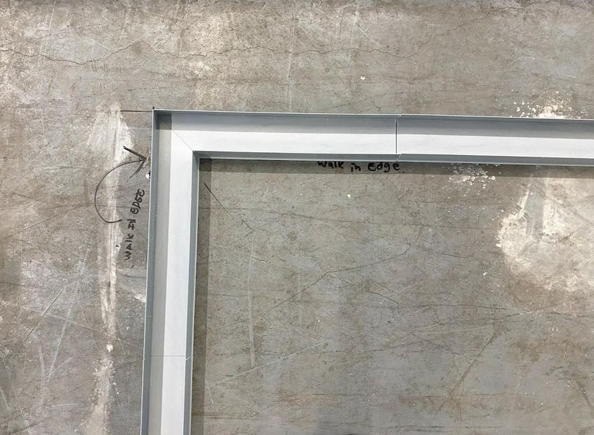
SUPPORT@STOREITCOLD.COM

Contents
IMPORTANT PLANNING INFORMATION ................................................................................................... 3
SHIPPING INFORMATION ......................................................................................................................... 4
WARRANTY INFORMATION ...................................................................................................................... 6
MINIMUM RECOMMENDED CLEARANCES FOR WALK-IN COOLER INSTALLATION ................................. 8
TOOLS NEEDED ......................................................................................................................................... 9
RECEIVING-INSPECTING & UNPACKING ................................................................................................. 10
IDENTIFYING PANELS .............................................................................................................................. 13
CAM-LOCK MECHANISM ........................................................................................................................ 14
WALK-IN COOLER INSTALLATION - COOLERS WITH FLOOR ................................................................... 15
WALK-IN COOLER INSTALLATION - COOLERS WITH NO FLOOR ............................................................. 26
OUTDOOR PACKAGE INSTALLATION (OUTDOOR COOLERS) .................................................................. 37
   A/C HOOD INSTALLATION................................................................................................................... 38
   MEMBRANE INSTALLATION ON SMALL COOLERS .............................................................................. 38
   MEMBRANE INSTALLATION ON LARGE COOLERS .............................................................................. 44
   DOOR CAP - RAIN GUTTER .................................................................................................................. 48
A/C INSTALLATION .................................................................................................................................. 51
ELECTRICAL INSTALLATION ..................................................................................................................... 58
   REQUIRED ELECTRICAL AND CONNECTIONS ...................................................................................... 59
   ELECTRICAL WIRING FOR THE DOOR PANEL ...................................................................................... 62
   ELECTRICAL WIRING FOR AUXILIARY LIGHTS – 4’ LED LIGHTS ........................................................... 62
   LIGHT SWITCH, THERMOMETER AND LIGHT FIXTURE ....................................................................... 64
COOLBOT PRO INSTALLATION ................................................................................................................ 64
OPERATION TIPS AND MAINTENACE ...................................................................................................... 65
   OPERATION ......................................................................................................................................... 65
   ROUTINE CLEANING OF ENCLOSURE .................................................................................................. 66
   ROUTINE CLEANING OF THE A/C UNIT ............................................................................................... 66
   PERIODIC INSPECTIONS ...................................................................................................................... 67
   DOOR CLOSER ADJUSTMENTS ............................................................................................................ 67
   DOOR GASKET REPLACEMENT............................................................................................................ 68
   DOOR SWEEP REPLACEMENT ............................................................................................................. 69

2021© Store It Cold, LLC.                                              2                              Rev 2021-08A. All Rights Reserved.
SUPPORT@STOREITCOLD.COM

            IMPORTANT PLANNING INFORMATION
LOCAL REGULATIONS AND CODES
It is YOUR responsibility to consult with your local inspectors about your walk-in cooler plans to
ensure you will be able to meet all the local codes and requirements for walk-in cooler installations
in your area.

WALK-IN COOLER WALLS CLEARANCE
A minimum of 2 inches clearance between existing building walls and walk-in walls is necessary for
proper air circulation around the cooler walls (pg. 7).

AIR CONDITIONER CLEARANCE
A minimum of 2 feet clearance around the A/C unit is needed for proper ventilation (pg. 7).

FLOOR
A SUCCESSFUL INSTALLATION begins with HAVING A SOLID LEVEL SURFACE to install your cooler.

DELIVERY
You will need 2-3 able bodied people on site for unloading your cooler. It is at the driver’s discretion
to use the lift gate. You should be prepared if the shipment has to be uncrated and unloaded
manually from the truck.

CONCRETE/TILED FLOORS
Always consult with your General Contractor before installation of your walk-in box in a recently
poured concrete pad or tiled floor to ensure enough curing time has been allowed.
Concrete, grout, and other construction materials may outgas chemicals for weeks (or even months)
that can cause staining/corrosion of walk-in cooler metal surfaces. Muriatic acid liquid and fumes,
which is often used by concrete contractors, will also cause staining/corrosion. We recommend that
our customers and their General Contractors fully understand the cure time of the concrete, tile
grout, and any other materials in proximity to the walk-in and provide adequate ventilation to move
these gases out and away from the walk-in cooler. Inadequate ventilation or ventilation for too short
of a time may result in staining/corrosion of walk-in cooler metal. This staining/corrosion is not
covered by warranty. If in doubt, contact your concrete supplier, tile contractor, general contractor,
etc. for the number of days for the concrete, grout, and other construction materials to have fully
outgassed and install your walk-in cooler after this date.

2021© Store It Cold, LLC.                        3                    Rev 2021-08A. All Rights Reserved.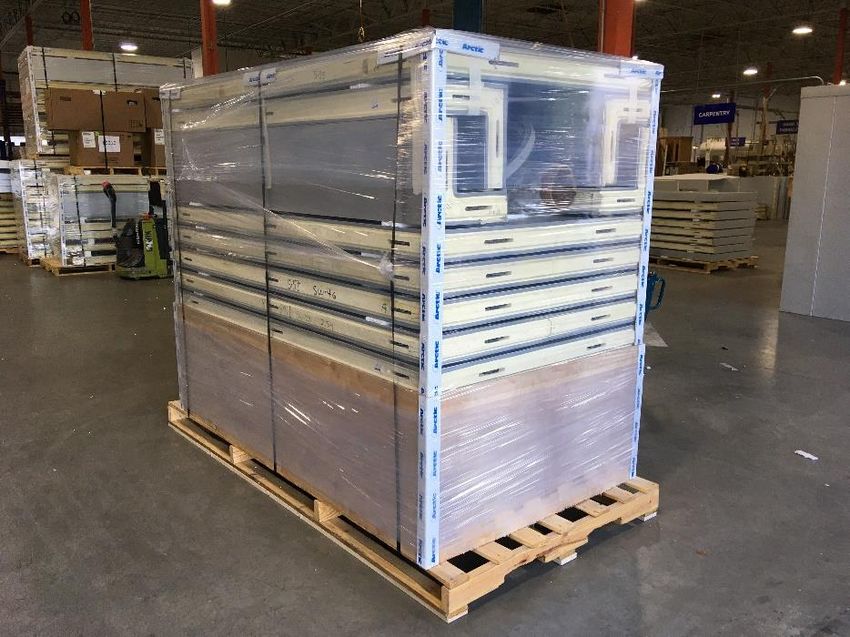
SUPPORT@STOREITCOLD.COM
SHIPPING INFORMATION
Please read carefully this section. It contains important information regarding your
shipment and instructions on receiving, inspecting, and filing claims if necessary.
• Your CoolBot Walk-in Cooler System includes:
1. A panel Enclosure (walk-in box)
2. An A/C unit
3. One box with Set-Up Drawing, installation hardware and a CoolBot Pro Temperature
Controller
4. An Outdoor Package if you have an outdoor cooler
• You will be provided with shipment tracking information and estimated delivery times.
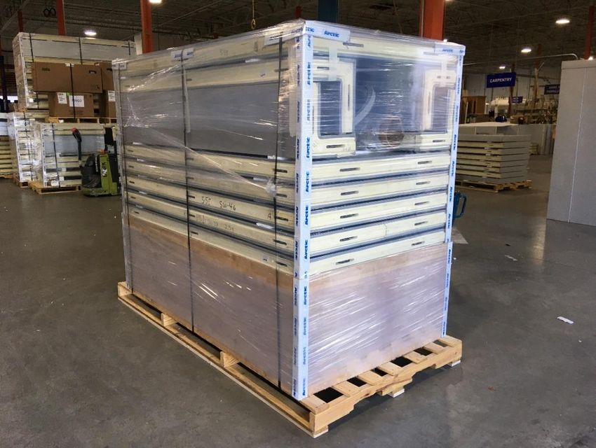
• Your Cooler has been palletized at the factory in an effort to reduce possible damage during
transportation. Please be careful unpacking your cooler, use good judgement and do not use
saws, electrical saws, or anything similar that can cause damage to the inside contents (the
cooler). A utility knife, metal cutting hand snips, a small crowbar and a hammer should be used
to carefully unpack your cooler.
• Your walk-in cooler will be transported and delivered on a commercial LTL delivery truck. The
receiver will be responsible for providing appropriate access to the delivery vehicle and all
necessary manpower to safely unload the pallets from the carrier.
• 2-3 able bodied people are required on site for delivery. It is at the driver’s discretion to use
the lift gate. You should be prepared to unpack the cooler inside the truck before unloading.
• At the discretion of the driver, if the possibility of using the lift gate to unload the pallet exists,
the receiver is responsible for ensuring a solid surface for unloading the pallet where it can be
rolled out of the lift gate and be left on the ground.
• The driver is NOT expected to help unpack the cooler NOR to take back any shipping materials
left after unpacking. It is at the driver’s discretion to provide any necessary assistance.
• See important information in case of transit damage on next page.
2021© Store It Cold, LLC. 4 Rev 2021-08A. All Rights Reserved.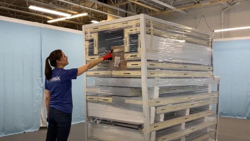
SUPPORT@STOREITCOLD.COM

                                        IMPORTANT!
                                PLEASE DO NOT REFUSE SHIPMENTS
                   YOU ARE REQUIRED TO CONTACT US BEFORE REFUSING A SHIPMENT

      • INSPECT SHIPMENT AND DOCUMENT ANY VISIBLE DAMAGES ON THE DELIVERY
        RECEIPT BY MARKING IT “DAMAGED”
      • HAVE THE DRIVER SIGN IT AND RETAIN A COPY FOR YOUR RECORDS
      • TAKE PICTURES OF THE DAMAGE BEFORE UNCRATING AND CONTACT OUR SUPPORT
        TEAM WHITHIN 24HRS AT COOLER@STOREITCOLD.COM

        IF YOU ARE PICKING UP AT A CARRIER TERMINAL, TAKE PICTURES OF THE SHIPMENT
        AND DOCUMENT ANY VISIBLE DAMAGES ON THE PICKUP RECEIPT BY MARKING IT
        “DAMAGED” BEFORE LOADING IN YOUR VEHICLE.

2021© Store It Cold, LLC.                    5                Rev 2021-08A. All Rights Reserved.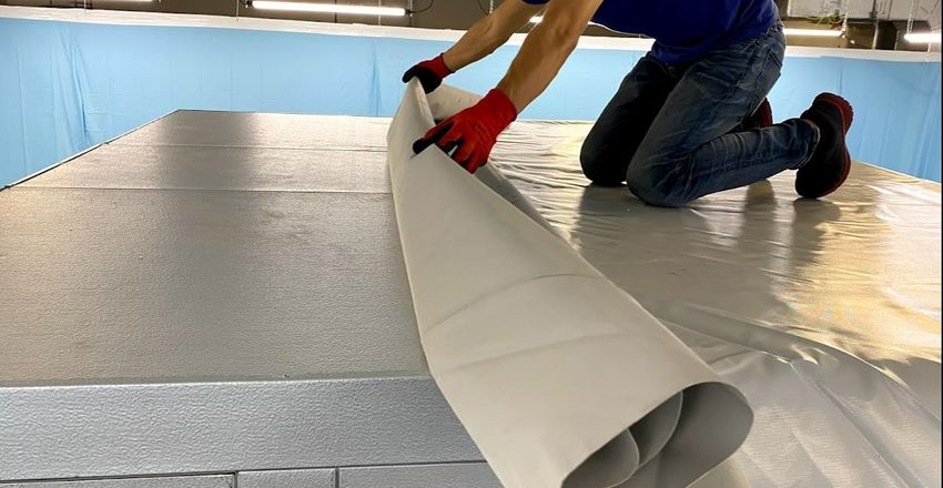
SUPPORT@STOREITCOLD.COM

                            WARRANTY INFORMATION
        ALL COOLBOT WALK-IN COOLER SALES ARE FINAL, INCLUDING ALL ITS COMPONENTS -
                ENCLOSURE, A/C UNIT, AND COOLBOT PRO DIGITAL CONTROLLER.

ENCLOSURE 10 YEAR LIMITED WARRANTY
Store It Cold, LLC., warrants to the original purchaser-user, that the prefabricated insulated panels
or doors manufactured by the company are free from any defect in material or workmanship under
the conditions of normal use and service, provided that it remains in the location where originally
installed. The company’s obligation under this warranty shall be limited to repairing or replacing at
our option, FOB factory, any of the covered parts of said walk-in which proved defective within ten
(10) years from the date of original installation.
Component parts, hardware and accessories are warranted for a period of one (1) year from date of
shipment.
This warranty does not apply to equipment which has been subject to any accident, fire, negligence,
alteration, damage in transit*, abuse, misuse, or improper installation. This warranty does not
include any labor charge for removal of defective parts or installation of replacement parts or
transportation to or from our factory.
THIS WARRANTY IS EXPRESSLY IMPLIED IN LIEU OF ANY OTHER WARRANTIES, EXPRESSED OR
IMPLIED, INCLUDING ANY IMPLIED WARRANTY OF MERCHANTABILITY OR FITNESS FOR A
PARTICULAR PURPOSE AND OF ALL OTHER LIABILITIES OR OBLIGATIONS WHATSOEVER, ON
STORE IT COLD, LLC’S PART, UNDER NO CIRCUMSTANCES, WHATSOEVER, SHALL STORE IT COLD,
LLC., BE LIABLE TO THE PURCHASER OR ANY OTHER PARTY FOR ANY SPECIAL OR CONSEQUENTIAL
DAMAGES.
THIS WARRANTY IS NON-TRANSFERABLE
OTHER EXCLUSIONS TO THIS WARRANTY:

    •   Normal maintenance or repairs
    •   Damage or loss of product, property, income or profit
    •   Floor panels subjected to wet mopping, flood, water leak, pallet jacks or weight exceeding
        600 lbs/sq ft
    •   Damage by flood, earthquake or other natural disasters

*Please see SHIPPING section on page 5 for details on transit damage.

2021© Store It Cold, LLC.                       6                    Rev 2021-08A. All Rights Reserved.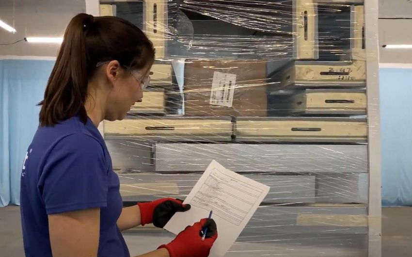
SUPPORT@STOREITCOLD.COM

A/C UNIT 1 YEAR LIMITED WARRANTY
Your A/C unit carries a 1 Year limited warranty. Please contact SIC to facilitate a warranty claim of
your A/C unit during this period.
IMPORTANT! Please refer to the Owner’s Manual of the A/C unit to follow recommendations about
installation and operation of your A/C unit.
This warranty will NOT cover claims due to improper installation or improper electrical supply to the
A/C unit.

COOLBOT PRO DIGITAL CONTROLLER 1 YEAR LIMITED WARRANTY
DISCLAIMER: By using the CoolBot Pro temperature controller, you (the “User”) acknowledge there
are inherent hazards in getting an air-conditioner (“A/C”) to do something it was not originally
designed to do, and that these inherent hazards cannot be ameliorated, mitigated or obviated while
still maintaining the essential functionality of the CoolBot. User accepts all responsibility in the use of
and monitoring of the CoolBot Pro and A/C. User assumes all risk of loss of property or product due
to improper functioning of the CoolBot Pro (or A/C). User assumes all risk of injury and warrants that
he/she will defend, indemnify and hold the seller harmless for any direct or consequential harm or
damage that may result from the use of this product.
LIMITED WARRANTY: CoolBot Pro controllers are warranted against defects for 1 year, not
including damage due to misuse or accidents. To double the warranty on your CoolBot Pro
controller visit us at: https://www.storeitcold.com/testimonials-form/

2021© Store It Cold, LLC.                         7                     Rev 2021-08A. All Rights Reserved.
SUPPORT@STOREITCOLD.COM

   MINIMUM RECOMMENDED CLEARANCES FOR
        WALK-IN COOLER INSTALLATION

2021© Store It Cold, LLC.   8   Rev 2021-08A. All Rights Reserved.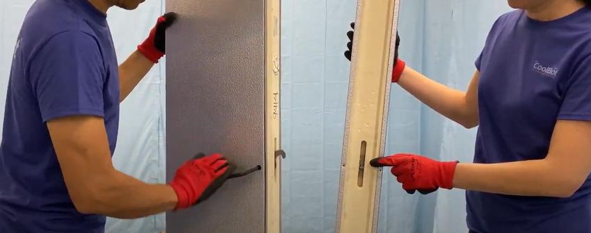
SUPPORT@STOREITCOLD.COM

                                    TOOLS NEEDED
    •    Level
    •    Metal hand snips
    •    Power screwdriver
    •    Hammer or plastic mallet
    •    Heavy duty work gloves
    •    Safety glasses
    •    Tape measure
    •    Caulk Gun
    •    Utility Knife
    •    Ladder
    •    Step Ladder

           ALWAYS WEAR GLOVES WHEN MOVING AND HANDLING WALK-IN COOLER PANELS

             YOUR WALK-IN COOLER PANELS, DOOR, SCREEDING, HARDWARE, OR OUTDOOR
             PACKAGE MIGHT DIFFER IN DESIGN OR LOOKS FROM THE ONES SHOWN IN THIS
                             MANUAL AND THE INSTALLATION VIDEO.

2021© Store It Cold, LLC.                  9                Rev 2021-08A. All Rights Reserved.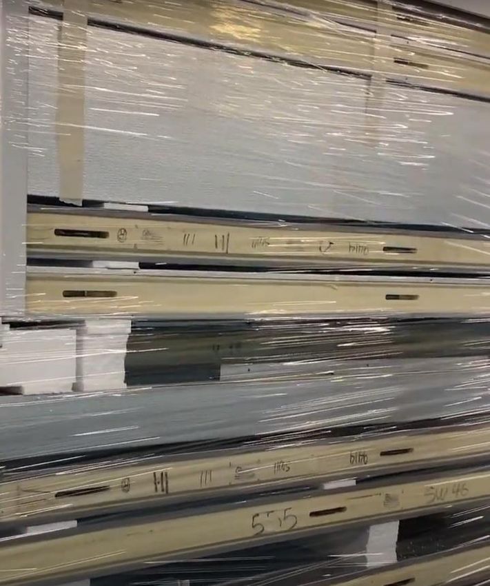
SUPPORT@STOREITCOLD.COM

             RECEIVING-INSPECTING & UNPACKING
           ALWAYS WEAR GLOVES WHEN MOVING AND HANDLING WALK-IN COOLER PANELS

When receiving, and before unpacking, inspect your shipment and document any visible damages on
the Delivery Receipt as “DAMAGED”. Have the driver sign it and retain a copy for your records. Take
pictures of the damages before uncrating and contact our support team.

Every shipment is clearly marked with a job number and the number of pallets included. The job
number is also written on the side of the walk-in panels for reference.

2021© Store It Cold, LLC.                     10                  Rev 2021-08A. All Rights Reserved.
SUPPORT@STOREITCOLD.COM Please be careful unpacking your cooler, use good judgement and do not use saws, electrical saws, or anything similar that can cause damage to the inside contents (the cooler). A utility knife, metal cutting hand snips, a small crowbar and a hammer should be used to carefully unpack your cooler. Locate your parts box in the contents of the shipment. Inside, you will find the Packing list, Set-Up Drawings, Assembly Wrench, the CoolBot Pro Controller and other installation hardware. Review the Packing List and thoroughly inspect all contents of the shipment. Report any shortages or concealed damages to our support team. 2021© Store It Cold, LLC. 11 Rev 2021-08A. All Rights Reserved.
SUPPORT@STOREITCOLD.COM

DO NOT store the air conditioner on the side, back or front. If the Air Conditioner has been on the
side or upside down, please set the unit on the correct position and let it stand for a period of at
least 24 hours before installing.

2021© Store It Cold, LLC.                       12                   Rev 2021-08A. All Rights Reserved.
SUPPORT@STOREITCOLD.COM

                             IDENTIFYING PANELS
     Enclosed with the contents of your cooler, inside the hardware box, is a Set-Up Drawing,
          showing the identification and proper placement of your walk-in cooler panels.

Look at the Set-Up Drawing, to familiarize yourself with the layout of the cooler and use it
throughout the installation of the walk-in.

For convenience at assembling, all panels have been marked at the factory with a part number using
a sticker or a number written on the side of the panel. This allows you to identify the position of each
panel in the cooler’s layout using the Set-Up Drawing.

2021© Store It Cold, LLC.                       13                   Rev 2021-08A. All Rights Reserved.
SUPPORT@STOREITCOLD.COM
CAM-LOCK MECHANISM
Before starting to put your enclosure together, familiarize yourself with the operation of the Cam-
lock mechanism.
Locks will be on the right side of the panel, and they operate in a clockwise rotation to lock. They
are accessible through the small holes on the right side of the panel.
Insert the 5/16” Hex Wrench provided with your Installation package, and after the panels have
been carefully aligned, turn approximately ¾ of a full turn until panels are securely locked
together.
DO NOT OVERTGHTEN! It will strip the Hex hole and damage the mechanism.
DO NOT drive the Hex Wrench with a hammer as this can damage the lock.
This locking mechanism is reversible. Simply rotate in the opposite direction to release the lock and
adjust. Don’t forget to lock your panel again after adjustments have been made.
2021© Store It Cold, LLC. 14 Rev 2021-08A. All Rights Reserved.SUPPORT@STOREITCOLD.COM
WALK-IN COOLER INSTALLATION
COOLERS WITH FLOOR
YOUR WALK-IN COOLER PANELS, DOOR, SCREEDING, HARDWARE, OR OUTDOOR
PACKAGE MIGHT DIFFER IN DESIGN OR LOOKS FROM THE ONES SHOWN IN THIS
MANUAL AND THE INSTALLATION VIDEO.
YOUR WALK-IN COOLER HAS BEEN PRE-ASSEMBLED AT THE FACTORY BEFORE
SHIPPING TO ENSURE PROPER FIT OF ALL PANELS AND TO ENSURE CORRECT DOOR
OPERATION.
IN ORDER TO HAVE AN EFFICIENT AND SAFE INSTALLATION, IT IS IMPORTANT TO
MAKE SURE THE INSTALLATION AREA IS CLEAN AND FREE OF DEBRIS
THE FIRST STEP IN A SUCCESSFUL WALK-IN COOLER INSTALLATION IS MAKING SURE
THAT YOU HAVE A FLAT LEVEL SURFACE FREE OF DEBRIS TO INSTALL YOUR COOLER. IF
YOUR FLOOR IS NOT LEVEL, THE DOOR MAY NOT FUNCTION PROPERLY AND THE
PANELS MAY NOT SEAL PROPERLY
1. Set the floor panels according to the Set-Up Drawing included in your documentation. All
panels have labels and are identified in the drawing.
The stickers on the floor panels may not all be in the same position. Ignore
the sticker position with respect to the floor layout when assembling and
guide yourself using the Set-Up Drawing and the panel identifier.
2021© Store It Cold, LLC. 15 Rev 2021-08A. All Rights Reserved.SUPPORT@STOREITCOLD.COM
2. Make sure that all floor panels are level. If not, use shims under the floor panels around the
seams and perimeter and located under the position of the cam-locks to level the floor.
2021© Store It Cold, LLC. 16 Rev 2021-08A. All Rights Reserved.SUPPORT@STOREITCOLD.COM
3. After all floor panels are level, firmly lock all floor panels together with the Hex Wrench
provided in your installation package. Turn it approximately ¾ of a full turn and repeat until
all floor panels are securely and properly locked together.
4. DO NOT START YOUR WALLS UNTIL YOU ARE CERTAIN THAT THE FLOOR ASSEMBLY IS
COMPLETELY LEVEL (FRONT TO BACK AND LEFT TO RIGHT). Begin with a corner panel. A
back corner or the least accessible corner is a good place to start. Use the wrench to secure
the panel to the floor. Check for alignment to make sure the panel is flush with the floor
panel at all seams and the corner.
2021© Store It Cold, LLC. 17 Rev 2021-08A. All Rights Reserved.SUPPORT@STOREITCOLD.COM
5. Select the next adjacent wall panel, going around the perimeter. Before locking the wall
panels together, always make sure they are flush at the top, flush along their seam and with
the floor panel. Lock the wall panels together and then lock them to the floor.
6. Repeat this procedure with each wall panel working your way around the perimeter of the
cooler in both directions. Align and lock, always making sure that panel is flush on all sides
and on top with the adjacent panels and the floor. Make sure that the top of each wall
adjacent panel is flush with each other.
If the wall panels have a stair-step appearance at the top, most likely
the floor is not level. In that case, stop immediately and follow the
previous instructions on leveling the floor (Step 2)
2021© Store It Cold, LLC. 18 Rev 2021-08A. All Rights Reserved.SUPPORT@STOREITCOLD.COM
7. When installing the door panel, DO NOT REMOVE THE DOOR FROM DOOR FRAME. Coolers
with a floor are shipped with metal banding or a metal brace to keep the legs framed and
secured. DO NOT CUT the “shipping metal band” or remove the “metal brace” at the
bottom of the door panel. They will be covered after installation by the door threshold.
Follow the same recommendations as when installing the wall panels. Door frame panel
must be LEVEL and PLUMB before locking in position. Ensure it is flush at the top with all
wall adjacent panels. If you have a cooler with a floor, DO NOT screw-in the door threshold
yet.
On coolers with a floor, DO NOT cut the metal bands.
On coolers with a floor, DO NOT remove the metal brace.
GENERAL TIPS FOR PROPER DOOR INSTALLATION ON COOLER WITH A FLOOR
• A level floor is a MUST
• Check for level and plumb of the door frame
• Check that the opening width at bottom of doorway matches the width atop of
doorway.
• Verify function of door, door lock and emergency release when door is locked.
• Adjust door closer if needed (see instructions on page 67).
2021© Store It Cold, LLC. 19 Rev 2021-08A. All Rights Reserved.SUPPORT@STOREITCOLD.COM
DOOR KEYS ARE TAPED TO THE HANDLE
8. Proceed to install the rest of the wall panels in the same way the other wall panels were
installed, leaving the front left or right corner for last.
2021© Store It Cold, LLC. 20 Rev 2021-08A. All Rights Reserved.SUPPORT@STOREITCOLD.COM
9. Close the wall enclosure by installing the last wall panel (a corner panel) and give a last check
around your box to make sure all surfaces are flush and the top edges of the walls are all
level.
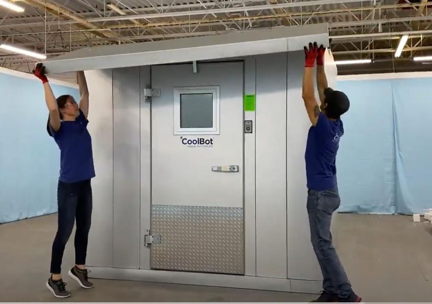
10. Select the first ceiling panel from your Set-up Drawing and place it on the corresponding side
of the cooler indicated in the drawing. Ensure that it sits properly on the tongue and groove
edges and that it is flush with the corners and walls on the outside.
2021© Store It Cold, LLC. 21 Rev 2021-08A. All Rights Reserved.SUPPORT@STOREITCOLD.COM
11. Lock the ceiling panel to the wall panels using the Hex Wrench.
GENERAL TIPS FOR CEILING INSTALLATION
In larger walk-ins, with sides 10 feet or longer, it may be appropriate to lock the
ceiling panels to the walls as you go. Lock every ceiling panel to previous one, and
then lock it to the walls while ensuring that all seams and joints are flush on the
outside.
On smaller walk-ins, all ceiling panels can be laid out and locked together first.
Once the whole ceiling assembly is flush with the walls and corners, proceed to lock
the ceiling panels to the walls.
12. Proceed with the next adjacent ceiling panel marked in your drawing, making sure that it sits
properly on all the tongue and groove edges and that it is flush with the corners and walls on
the outside. Lock the panel to the adjacent panel first and then lock the panel to the walls.
2021© Store It Cold, LLC. 22 Rev 2021-08A. All Rights Reserved.SUPPORT@STOREITCOLD.COM
13. Install the last ceiling panel to close the box.
14. IMPORTANT!!
Check the box around one last time. Seams in between panels should be tight.
Check the door for correct operation. Open the door at 90° and let it close by itself. Make
sure it closes freely and makes a good seal with the frame. Ensure the door does not hit or
rub against any parts of the frame. A door that is not closing properly is usually the result
of unlevel set-up and/or improper installation. Please unlock the necessary wall and
ceiling panels, and correct positioning and leveling until the door operates properly.
2021© Store It Cold, LLC. 23 Rev 2021-08A. All Rights Reserved.SUPPORT@STOREITCOLD.COM
15. Cover wrench holes with the plastic buttons provided in the installation kit. Use a plastic or
regular hammer to gently tap them in place. If the plastic button is falling because the hole
was bored a tad bigger, you can use a small amount of silicone on the back of the button
to keep the plastic cover in place.
16. Anchor the included threshold by using the included self-drilling metal screws and by
screwing them into the floor panel (illustration 1). Coolers without an insulated floor DO NOT
include a threshold.
2021© Store It Cold, LLC. 24 Rev 2021-08A. All Rights Reserved.SUPPORT@STOREITCOLD.COM
17. Enclosure set-up finished
2021© Store It Cold, LLC. 25 Rev 2021-08A. All Rights Reserved.SUPPORT@STOREITCOLD.COM
WALK-IN COOLER INSTALLATION
COOLERS WITH NO FLOOR
YOUR WALK-IN COOLER PANELS, DOOR, SCREEDING, HARDWARE, OR OUTDOOR
PACKAGE MIGHT DIFFER IN DESIGN OR LOOKS FROM THE ONES SHOWN IN THIS
MANUAL AND THE INSTALLATION VIDEO.
YOUR WALK-IN COOLER HAS BEEN PRE-ASSEMBLED AT THE FACTORY BEFORE
SHIPPING TO ENSURE PROPER FIT OF ALL PANELS AND TO ENSURE CORRECT DOOR
OPERATION.
IMPORTANT NOTE FOR COOLERS WITH NO FLOOR!
Having a successful cooler installation begins with HAVING AN EXISTING LEVEL
SURFACE TO ASSEMBLE YOUR COOLER. If the floor is slightly unlevel, it will be
necessary to install shims under the wall panels inside the vinyl screed until the
wall panels are flush at the top.
THE FIRST STEP IN A SUCCESSFUL WALK-IN COOLER INSTALLATION IS MAKING SURE
THAT YOU HAVE A FLAT LEVEL SURFACE FREE OF DEBRIS TO INSTALL YOUR COOLER. IF
YOUR FLOOR IS NOT LEVEL, THE DOOR MAY NOT FUNCTION PROPERLY AND THE
PANELS MAY NOT SEAL PROPERLY
NOTE
The vinyl screed has been pre-cut at the factory to match the layout of your cooler.
If you have to cut a piece of screed you can use a miter saw or a hand saw. A piece
numbered “0” may be included as an extra piece.
2021© Store It Cold, LLC. 26 Rev 2021-08A. All Rights Reserved.SUPPORT@STOREITCOLD.COM
1. Use a chalk line to mark the installation area to the dimensions of the walk-in as shown in
the Set-Up Drawing. Measure diagonally from corner to corner to be sure the layout is
square.
2. Before starting to assemble the walls, apply TWO straight beads of caulking along the
bottom of the vinyl screed (about an inch away from the edges) to provide a seal between
screed and floor, then place the vinyl screed along the chalk lines and proceed with the
installation of the walls.
2021© Store It Cold, LLC. 27 Rev 2021-08A. All Rights Reserved.SUPPORT@STOREITCOLD.COM
3. Begin with a corner panel. The back corner or the least accessible corner is a good place to
start. Stand the wall panel inside the screed making sure it sits correctly (fully cradled in the
screeding).
4. Find the next adjacent wall panel according to your Set-Up Drawing and proceed to install
inside the screed and then lock to the corner panel.
5. If the wall panels have a stair-step appearance at the top, the floor is not level. In that
case, stop immediately. On a slightly unlevel surface, install small shims under the panels
inside the vinyl screed. Check for alignment to make sure the panels are flush with each
other as you proceed. If they are not, loose the cam-locks, shim as necessary, adjust, and
lock again until they are level and flush atop and flush along their vertical seams.
2021© Store It Cold, LLC. 28 Rev 2021-08A. All Rights Reserved.SUPPORT@STOREITCOLD.COM
6. Repeat this procedure with each wall panel working your way around the perimeter of the
cooler in both directions. Align and lock, always making sure that panel is flush on all sides
and on top with the adjacent panels. Make sure that the top of each wall adjacent panel is
flush with the others.
If the wall panels have a stair-step appearance at the top, most likely
the floor is not level. In that case, stop immediately and follow the
previous instructions on leveling (Step 5).
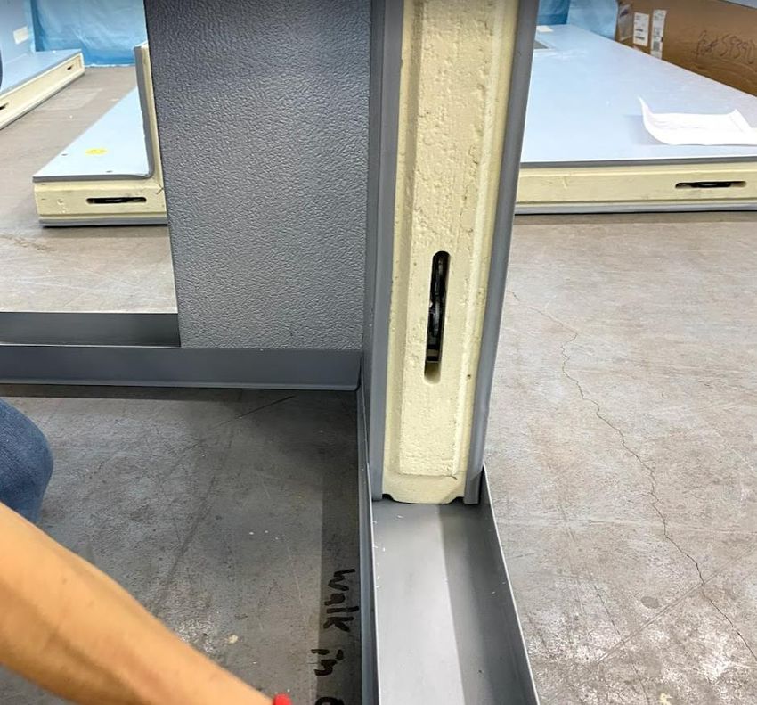
7. When installing the door panel, DO NOT REMOVE THE DOOR FROM DOOR FRAME. Coolers
without a floor are shipped either with a metal brace or a wood brace.
• If your door was shipped with a metal brace at the bottom, REMOVE the metal brace
before installing the door panel by unscrewing the Philips screws from the bottom.
DO NOT install the door with the metal brace on. Coolers with no floor DO NOT have
a threshold (see pictures on next page)
• If your door is shipped with a wood brace, you can leave it during installation of the
door panel and remove later. Once door has been checked for operation and it is
ready to be anchored to the floor, you can remove the wood brace (see pictures on
next page).
2021© Store It Cold, LLC. 29 Rev 2021-08A. All Rights Reserved.SUPPORT@STOREITCOLD.COM
On coolers without a floor, if door On coolers without a floor, if door
panel was shipped with a METAL was shipped with a WOOD brace,
brace, REMOVE before installation. LEAVE during installation.
IMPORTANT!
Door and frames have been checked for proper fit and operation at the factory. An unlevel
floor may cause doors to not hang or close properly. This can occur at the time of installation
or later due to heavy traffic. It may be necessary to shim under the walk-in floor or door frames
at one side or the other to adjust a misaligned frame.
Loosening and relocking frame cam-locks may also permit some adjustment. Make sure legs
are parallel to each other and to adjacent wall panels. The door may not seal properly if the
frame is twisted or out of plumb. See figures on next page.
2021© Store It Cold, LLC. 30 Rev 2021-08A. All Rights Reserved.SUPPORT@STOREITCOLD.COM
TIPS FOR PROPER DOOR INSTALLATION ON COOLERS WITH NO FLOOR
• Level and plumb door frame. Small shims under door frame to ensure level and
plumb are achieved.
• Frame legs are to be in plane with each other. Check with 4’ straight edge across door
face at bottom of doorway (See figure below).
• Frame legs are to be parallel and not spread out. Opening width at bottom of
doorway to match width at top of doorway. (See fig. below)
• After all walls are installed, verify function of door, door locks and emergency release
when door is locked.
• Adjust door closer if needed (See page 67)
• Verify that door sweep lightly drags on floor when reaching closing position.
2021© Store It Cold, LLC. 31 Rev 2021-08A. All Rights Reserved.SUPPORT@STOREITCOLD.COM
DOOR KEYS ARE TAPED TO THE HANDLE
Cooler with a floor shown in picture. Assembly procedure for a cooler
with no floor is the same.
8. Proceed to install the rest of the wall panels in the same way the other wall panels were
installed, leaving the front left or right corner for last.
Cooler with a floor shown in picture. Assembly procedure for a cooler
with no floor is the same.
2021© Store It Cold, LLC. 32 Rev 2021-08A. All Rights Reserved.SUPPORT@STOREITCOLD.COM
9. Close the wall enclosure by installing the last wall panel (a corner panel) and give a last check
around your box to make sure all surfaces are flush, and the top edges of the walls are all
level.
Cooler with a floor shown in picture. Assembly procedure for a cooler
with no floor is the same.
10. Select the first ceiling panel from your Set-up Drawing and place it on the corresponding side
of the cooler indicated in the drawing. Ensure that it sits properly on the tongue and groove
edges and that it is flush with the corners and walls on the outside.
Cooler with a floor shown in picture. Assembly procedure for a cooler
with no floor is the same.
2021© Store It Cold, LLC. 33 Rev 2021-08A. All Rights Reserved.SUPPORT@STOREITCOLD.COM
11. Lock the ceiling panel to the wall panels using the Hex Wrench.
GENERAL TIPS FOR CEILING INSTALLATION
In larger walk-ins, with sides 10 feet or longer, it may be appropriate to lock the
ceiling panels to the walls as you go. Lock every ceiling panel to previous one, and
then lock it to the walls while ensuring that all seams, corners and joints are flush on
the outside.
On smaller walk-ins, all ceiling panels can be laid out and locked together first. Once
the whole ceiling assembly is flush with the walls and corners, proceed to lock the
ceiling panels to the walls.
12. Proceed with the next adjacent ceiling panel marked in your drawing, making sure that it sits
properly on all the tongue and groove edges and that it is flush with the corners and walls on
the outside. Lock the panel to the adjacent panel first and then lock the panel to the walls.
2021© Store It Cold, LLC. 34 Rev 2021-08A. All Rights Reserved.SUPPORT@STOREITCOLD.COM
13. Install the last ceiling panel to close the box.
Cooler with a floor shown in picture. Assembly procedure for a cooler
with no floor is the same.
14. IMPORTANT!!
Check the box around one last time. Seams in between panels should be tight.
Check the door for correct operation. Open the door at 90° and let it close by itself. Make
sure it closes freely and makes a good seal with the frame. Ensure the door does not hit or
rub against any parts of the frame. A door that is not closing properly is usually the result
of unlevel set-up and/or improper installation. Please unlock the necessary wall and ceiling
panels, and correct positioning and leveling until the door operates properly.
2021© Store It Cold, LLC. 35 Rev 2021-08A. All Rights Reserved.SUPPORT@STOREITCOLD.COM
15. Cover wrench holes with the plastic buttons provided in the installation kit. Use a plastic or
regular hammer to gently tap them in place. If the plastic button is falling because the hole
was bored a tad bigger, you can use a small amount of silicone on the back of the button
to keep the plastic cover in place.
Cooler with a floor shown in picture. Assembly procedure for a cooler
with no floor is the same.
16. Enclosure set-up finished
SECURING THE DOOR PANEL TO THE FLOOR (COOLERS WITH NO FLOOR)
Install anchoring brackets ONLY after cooler is assembled and the door has been checked for correct
operation and door frame has been confirmed to be level and plumbed.
Coolers with no floor include the following hardware to anchor the door frame to the floor (inside):
• 2 Angle pieces – 16-gauge clips with 1/4” pre-drilled holes
• 8 Anchors – (4) Tapcons & Self Drilling Metal Screws
STEP #2: Mark and drill pilot holes in concrete.
STEP 3#: Anchor to floor using tapcons and to
STEP #1: Place frame using sheet metal screws.
clips against
interior door
jambs.
2021© Store It Cold, LLC. 36 Rev 2021-08A. All Rights Reserved.SUPPORT@STOREITCOLD.COM
OUTDOOR PACKAGE INSTALLATION
(OUTDOOR COOLERS)
YOUR WALK-IN COOLER PANELS, DOOR, SCREEDING, HARDWARE, OR OUTDOOR PACKAGE
MIGHT DIFFER IN DESIGN OR LOOKS FROM THE ONES SHOWN IN THIS MANUAL AND THE
INSTALLATION
Electrical Installations and other penetrations should be done AFTER the outdoor
membrane has been installed. On outdoor coolers, all penetrations must go through the
side walls. DO NOT make penetrations on the roof membrane.
Included items of your outdoor package:
1. A/C hood
2. Door cap - rain gutter
3. Roof Membrane – pre-cut about 1 ft larger on each side
4. Membrane Trim - Flat bars
5. Installation Hardware:
a. Black long screws: For Truss-Plate anchors and for Trim
b. S/S or hex sheet metal screws: For A/C hood and door rain gutter
c. Truss-Plates (only to be used in coolers with a side equal or greater than 10 ft)
ROOF
A/C HOOD MEMBRANE
TRIM BARS
DOOR CAP
RAIN GUTTER
BLACK SCREWS TRUSS PLATES
2021© Store It Cold, LLC. 37 Rev 2021-08A. All Rights Reserved.SUPPORT@STOREITCOLD.COM
A/C HOOD INSTALLATION
Align the top edge of the hood about 1” below the horizontal joint in between the ceiling panel
and the wall panel. Make sure it’s centered in position with respect to the A/C opening. Screw in
place with the self-drilling metal screws.
MEMBRANE INSTALLATION ON SMALL COOLERS
- ALL SIDES ARE LESS THAN 10FT -
IMPORTANT
Improper installation of the roof membrane may result in water accumulation or water
infiltration through the membrane.
Snow accumulation of more than 3” must be carefully removed in a manner which does
not cause damage (tears, etc.) to the membrane roof cover.
DO NOT make penetrations on the roof membrane.
2021© Store It Cold, LLC. 38 Rev 2021-08A. All Rights Reserved.SUPPORT@STOREITCOLD.COM
1. Extend the membrane on the roof of the walk-in with the soft smooth semi-glossy textured
side UP (the overlapping seams will be facing DOWN). Ensure that it hangs approximately
the same amount on all sides. You should have the membrane hanging at least a 6” on each
side of the cooler. Don’t worry if it is too long, it can be trimmed after it’s installed in place.
MEMBRANE INSTALLATION IF THE OUTDOOR COOLER IS 2” FROM A WALL
2021© Store It Cold, LLC. 39 Rev 2021-08A. All Rights Reserved.SUPPORT@STOREITCOLD.COM
2. Starting at the front of the cooler, gently pull down on the membrane, make it flush against
the surface, and with a sharpie, make a couple guide marks 4 inches from the top. These
marks will be the top edge of the membrane trim bars.
3. Align the trim’s top edge with the guide marks from the previous step. With the sharpie mark
the pilot hole on the trim that is closest to the edge of the cooler.
IMPORTANT
If the trim’s anchoring hole lays directly on top of a seam between panels, make a new
hole a couple inches away from that hole. Never anchor the trim directly onto a wall
seam as it will damage the gasket.
2021© Store It Cold, LLC. 40 Rev 2021-08A. All Rights Reserved.SUPPORT@STOREITCOLD.COM
4. Pulling down and making sure the membrane is taut, use a stubby metal 9/64” drill bit to
make a pilot hole. Please ensure you do not use a long drill bit; pilot holes should not be
deeper than 1”- just long enough to penetrate the metal sheet of the panel.
5. Using one of the black screws included in the outdoor package, anchor the trim using the first
pilot hole. Now, with the trim’s top edge held in straight position along the side proceed to
drill and anchor the rest of the trim to that side of the cooler. Ensure that the trim is level
and the membrane is taut as you go.
2021© Store It Cold, LLC. 41 Rev 2021-08A. All Rights Reserved.SUPPORT@STOREITCOLD.COM
6. Repeat the same process for the back side of the cooler, making sure your membrane is
pulled taut towards the back.
7. After the front and back part of the membrane have been secured, proceed to one of the
sides of the cooler. Tuck the excess fabric at the front corner underneath the membrane to
create a nice fold. Pull down tight and start securing the membrane with the trim following
the same recommendations as before. Install the trimming at the same level as you did on
the front and back to remain constant around the perimeter of the cooler. Work your way
from front to back as you pull down tight and secure the trim.
2021© Store It Cold, LLC. 42 Rev 2021-08A. All Rights Reserved.SUPPORT@STOREITCOLD.COM
8. After the membrane has been correctly installed and secured to the sides of the cooler, you
can trim with a utility knife the excess fabric below the trim. While not necessary, this will
give a cleaner and more professional look.
9. Caulk with silicone the top edge of the trimming bars for added protection.
2021© Store It Cold, LLC. 43 Rev 2021-08A. All Rights Reserved.SUPPORT@STOREITCOLD.COM
MEMBRANE INSTALLATION ON LARGE COOLERS
ONE SIDE MEASURING 10FT OR MORE
IMPORTANT
Improper installation of the room membrane may result in water accumulation or water
infiltration through the membrane.
Snow accumulation of more than 3” must be carefully removed in a manner which does
not cause damage (tears, etc.) to the membrane roof cover.
DO NOT make penetrations on the roof membrane.
1. Extend your membrane on the roof of your walk-in with the soft smooth semi-glossy
textured side UP (overlapping seams DOWN). Ensure that it hangs approximately the same
amount on all sides. You should have the membrane hanging at least a 6” on each side of the
cooler. Don’t worry if it is too long, it can be trimmed after it’s installed in place.
2021© Store It Cold, LLC. 44 Rev 2021-08A. All Rights Reserved.SUPPORT@STOREITCOLD.COM
2. Find the tabs (seams) on your membrane and ensure they are running parallel to one side, at
least 6” away from the closest edge of the cooler and perpendicular to the other side.
Note: Your membrane may only have one seam.
3. Once the membrane is centered on the roof, seams have been located and checked for
distance from the edge (previous step), either fold or roll the membrane back towards the
center of the roof so the underside fastening tabs are exposed. The roll or fold must be
parallel to the membrane seams (tabs).
4. When you reach the last tab (closest and parallel to one side of the cooler and furthest from
where you started rolling back) stop rolling or folding. NOTE: Your membrane may only have
one tab.
2021© Store It Cold, LLC. 45 Rev 2021-08A. All Rights Reserved.SUPPORT@STOREITCOLD.COM
5. The fastening tab should be flat on the walk-in cooler ceiling panel. Begin your membrane
installation by anchoring the TRUSS PLATES along the fastening tab. Start 6” away from the
side of the cooler and space your anchors 12” to 16” O.C. Make sure that your last anchor is
no closer than 6” from the edge. Drill pilot holes using a stubby metal 9/64” drill bit. Use the
black long screws provided.
6” FROM THE EDGE STAY AT LEAST 6” FROM ANY SEAM
NOTE: You are screwing into the Fastening Tab and into the ceiling of the cooler but once you
roll the rest of the membrane it SHOULD cover the Tab (flap) and the anchors as well, leaving
no exposed screws or penetrations
2021© Store It Cold, LLC. 46 Rev 2021-08A. All Rights Reserved.SUPPORT@STOREITCOLD.COM
6. Continue to roll the membrane until the next Tab (seam) is exposed (if applicable). Making
sure that the membrane is taut and straight, install your second row of anchors (TRUSS
PLATE) along that Fastening Tab in a similar fashion as the first one. Remember, once the
membrane is rolled completely, the Tab(s) will be covered, and no anchors or screws will be
visible from the top. Note: Your membrane may only have one seam.
2021© Store It Cold, LLC. 47 Rev 2021-08A. All Rights Reserved.SUPPORT@STOREITCOLD.COM
7. Continue the same way installing horizontal rows of anchors into every Fastening Tab making
sure your membrane is pulled tight each time.
8. Once you have installed all the TRUSS PLATES and the membrane is completely extended
over the ceiling, follow steps 2 to 9 from pages 40-43 (Membrane Installation for Small
Coolers).
MEMBRANE INSTALLATION IF THE OUTDOOR COOLER IS 2” FROM A WALL
DOOR CAP - RAIN GUTTER
For free-standing walk-ins where the door is exposed to the outside, a door cap to prevent water
from running down into the door gasket is provided.
1. Slightly loosen the screws of the trim that are in the vicinity of the door closer.
2021© Store It Cold, LLC. 48 Rev 2021-08A. All Rights Reserved.SUPPORT@STOREITCOLD.COM
2. With the door drip centered above the door, slide the flat side with the V cut under the trim
and above the door closer. The door drip should look like an inverted “V” above the door.
3. With a sharpie, make a mark on each side of the wall, 1 to 1.5 inches below the trim
4. With the drip edge aligned at the marks on each end, mark your pilot holes on the cooler
wall.
2021© Store It Cold, LLC. 49 Rev 2021-08A. All Rights Reserved.SUPPORT@STOREITCOLD.COM
5. Using a stubby metal 9/64” drill bit, no longer than 1 inch, drill the pilot holes marked on the
previous step. Attach the door drip to the frame above the door with the sheet metal screws
provided.
6. Retighten the trim screws above the door closer
7. Caulk the joint between the door drip and the wall.
8. Your CoolBot Walk-in Cooler is ready for outdoor use.
2021© Store It Cold, LLC. 50 Rev 2021-08A. All Rights Reserved.SUPPORT@STOREITCOLD.COM
A/C INSTALLATION
Please read the LG OWNER’S MANUAL supplied with the A/C unit to familiarize yourself
with the functions and operation of the LG air conditioner unit.
IMPORTANT!!
If the A/C unit was stored on the side or upside down, please set the unit in the correct
position and let the A/C stand for a period of at least 24Hrs before installing
2021© Store It Cold, LLC. 51 Rev 2021-08A. All Rights Reserved.SUPPORT@STOREITCOLD.COM
1. Carefully unpack the A/C unit out of the box. Make sure the A/C unit remains in the correct
position. DO NOT stand the box or the A/C unit on the side, back or front.
2. DO NOT discard any of the contents inside the box.
3. Once the unit is out of the box, remove the four (4) screws which fasten the cabinet. One on
each side at the front-lower section (A) and two at the back-lower section (B).
(A) (B)
2021© Store It Cold, LLC. 52 Rev 2021-08A. All Rights Reserved.SUPPORT@STOREITCOLD.COM
4. Slide the unit out of the cabinet by gripping the base pan handle and pulling forward while
bracing the cabinet.
5. Carefully insert the A/C cabinet on the pre-cut hole from the inside of the cooler and slide
towards the outside until the highest part of top bracket of the cabinet touches the wall
panel.
2021© Store It Cold, LLC. 53 Rev 2021-08A. All Rights Reserved.SUPPORT@STOREITCOLD.COM
6. Ensure that the cabinet has a slight tilt downward towards the outside. Position the
cabinet so that the back is about ½” to 1” lower than the front.
7. Use the holes at the bottom of the A/C cabinet to anchor the A/C cabinet to the panel. Use
the sheet metal screws provided with the walk-in cooler. No extra reinforcement is needed
and no brackets outside are needed to support the A/C. The walk-in panel will hold the A/C
securely in the A/C opening.
2021© Store It Cold, LLC. 54 Rev 2021-08A. All Rights Reserved.SUPPORT@STOREITCOLD.COM
8. Carefully slide the unit inside the A/C cabinet.
9. Install the four (4) cabinet screws you removed in step 3 to secure the unit to the cabinet.
2021© Store It Cold, LLC. 55 Rev 2021-08A. All Rights Reserved.SUPPORT@STOREITCOLD.COM
10. Use the foam strips provided with the A/C unit, to fill the gaps in between the wall opening
and the cabinet.
DO NOT USE SPRAY FOAM TO SEAL IN BETWEEN THE A/C ENCLOSURE AND THE WALL
PRO TIP
If you experience condensation around the A/C during operation of the walk-in cooler,
a great alternative to the foam strips included with the A/C, is to use closed-cell pipe
insulation available at all hardware stores (looks like a black pool noodle). Cut it in two
half-strips longways. Stuff the strips in between the A/C cabinet and the wall all the
way around the opening - including the bottom. Repeat on the outside.
NOTE: You can choose to do this now, at assembly, if you want to go the extra mile.
11. Do not install the A/C cover yet. It is easier to install the CoolBot Pro at this point and then
proceed to install the A/C cover to finish the installation. For CoolBot Pro controller
installation instructions please follow the Quick Start Guide included in the CoolBot Pro box.
CoolBot Pro Installation Video and the full CoolBot Pro Manual and App features available
at: https://www.storeitcold.com/build-it/install-your-coolbot/
12. When installing the front cover back on the A/C, ensure that you firmly connect the wire
harness from the cover to the plug located on the top right of the A/C unit.
HARNESS PLUG RECEPTACLE
WIRE HARNESS
2021© Store It Cold, LLC. 56 Rev 2021-08A. All Rights Reserved.SUPPORT@STOREITCOLD.COM
13. When securing the A/C cover back into the cabinet, after the CoolBot has been connected to
the A/C and the A/C harness has been securely connected (step 12), carefully route the
CoolBot Heater and Fins Sensor cables using the opening at the right side of the cover (1).
AVOID pinching the cables to prevent damage.
ROUTE COOLBOT CABLES HERE (1)
14. REMOVE THE A/C FILTER AFTER INSTALLING THE FRONT PANEL.
NOTE: Leaving the A/C filter will make the A/C ice up. DO NOT use it.
REMOVE THE FILTER!!
DO NOT USE!!
2021© Store It Cold, LLC. 57 Rev 2021-08A. All Rights Reserved.SUPPORT@STOREITCOLD.COM
ELECTRICAL INSTALLATION
IMPORTANT!!
Electrical installations SHOULD be performed by a qualified electrician to ensure correct power
supply, wiring, and compliance with National and Local Electrical Codes.
IMPORTANT!!
The enclosure does not have any predrilled holes or electrical outlets from the factory.
Drilling holes on the panels to run conduit, to bring power inside the cooler, is OK and will not
void the warranty of the panels as long as the installation is done by a qualified electrician.
All outlet boxes and junction boxes should be surface mounted.
On outdoor coolers, electrical installations should be done ONLY AFTER the outdoor membrane
has been installed. Make absolutely no roof penetrations for electricity or other services. All
penetrations on outdoor coolers must go through the side walls on outdoor coolers.
2021© Store It Cold, LLC. 58 Rev 2021-08A. All Rights Reserved.SUPPORT@STOREITCOLD.COM
ATTENTION ELECTRICIAN!!
To prevent condensation from forming inside the walk-in, and inside the electrical boxes or
the conduit, all incoming electrical conduit runs must be sealed externally (*1) where it
enters cold space, and internally at the junction box (*2)
REQUIRED ELECTRICAL AND CONNECTIONS
COOLERS WITH ONE 15K BTUs AIR CONDITIONER OR SMALLER (10K, 12K)
A dedicated 120V 15-amp circuit required
• The electrician will have to install:
o One 120V surface mount outlet box to plug in the CoolBot Controller and the A/C
inside the cooler - on the right side of the A/C.
o One 120V supply via conduit to the door panel light fixture/junction box, to
provide power to the light and the factory pre-wired light switch (see page 62).
• A/C plug configuration (10K, 12K & 15K BTU):
2021© Store It Cold, LLC. 59 Rev 2021-08A. All Rights Reserved.SUPPORT@STOREITCOLD.COM
COOLERS WITH ONE 18K BTUs AIR CONDITIONER
A dedicated 208/240V 15-amp circuit required
A dedicated 120V 15-amp circuit required
• The electrician will have to install:
o One 208/240V surface mount outlet box to plug in the A/C inside the cooler - on the
right side of the A/C.
o One 120V surface mount outlet box to plug in the CoolBot Controller inside the cooler
- on the right side of the A/C.
o One 120V supply via conduit to the door panel light fixture/junction box, to
provide power to the light and the factory pre-wired light switch (see page 62).
• A/C plug configuration (18K BTU):
COOLERS WITH ONE 24K BTUs AIR CONDITIONER
A dedicated 208/240V 20-amp circuit required
A dedicated 120V 15-amp circuit required
• The electrician will have to install:
o One 208/240V surface mount outlet box to plug in the A/C inside the cooler - on the
right side of the A/C.
o One 120V surface mount outlet box to plug in the CoolBot Controller inside the cooler
- on the right side of the A/C.
o One 120V supply via conduit to the door panel light fixture/junction box, to
provide power to the light and the factory pre-wired light switch (see page 62).
• A/C plug configuration (24K BTU):
2021© Store It Cold, LLC. 60 Rev 2021-08A. All Rights Reserved.SUPPORT@STOREITCOLD.COM
COOLERS WITH TWO 15K BTUs AIR CONDITIONERS
Two dedicated 120V 15-amp circuits required
• The electrician will have to install:
o Two 120V surface mount outlet boxes to plug in the CoolBot Controllers and the A/Cs.
One outlet box per CoolBot and A/C inside the cooler - on the right side of each A/C.
o One 120V supply via conduit to the door panel light fixture/junction box, to
provide power to the light and the factory pre-wired light switch (see page 62). The
door panel connection can be hooked up to either one of the two dedicated circuits -
shared with one A/C and one CoolBot.
• A/Cs plug configuration (15K BTUs):
COOLERS WITH TWO 18K BTUs AIR CONDITIONERS
Two dedicated 208/240V 15-amp circuits required
A dedicated 120V 15-amp circuit required
• The electrician will have to install:
o Two 208/240V surface mount outlet boxes to plug in the A/Cs, inside the cooler – one
outlet box per A/C and installed on the right side of each A/C.
o Two 120V surface mount outlet boxes to plug in the CoolBot Controllers, inside the
cooler – one outlet box per CoolBot and installed on the right side of each A/C.
o One 120V supply via conduit to the door panel light fixture/junction box, to
provide power to the light and the factory pre-wired light switch (see page 62).
• A/Cs plug configuration (18K BTUs):
2021© Store It Cold, LLC. 61 Rev 2021-08A. All Rights Reserved.SUPPORT@STOREITCOLD.COM
COOLERS WITH TWO 24K BTUs AIR CONDITIONERS
Two dedicated 208/240V 20-amp circuits required
A dedicated 120V 15-amp circuit required
• The electrician will have to install:
o Two 208/240V surface mount outlet boxes to plug in the A/Cs, inside the cooler – one
outlet box per A/C and installed on the right side of each A/C.
o Two 120V surface mount outlet boxes to plug in the CoolBot Controllers, inside the
cooler – one outlet box per CoolBot and installed on the right side of each A/C.
o One 120V supply via conduit to the door panel light fixture/junction box, to
provide power to the light and the factory pre-wired light switch (see below).
• A/Cs plug configuration (24K BTUs):
ELECTRICAL WIRING FOR THE DOOR PANEL
ATTENTION ELECTRICIAN!
The only connection you have to do at the door panel is at the light fixture.
Bring 120V supply through the ceiling or wall via conduit into the light fixture.
Connect inside the junction box to the white, black, and ground cables.
Wiring Diagram on next page for reference.
See pictures on next page on how to access the junction box/light fixture to connect the 120V
incoming supply.
ELECTRICAL WIRING FOR AUXILIARY LIGHTS – 4’ LED LIGHTS
All LED auxiliary lights must be connected via conduit using the red cable connection at the door light
fixture/junction box as their hot line. All connections MUST be made by a qualified electrician to
ensure compliance with National and Local Electrical Codes.
The sum of all lights installed in the cooler MUST NOT exceed 10 amps total.
2021© Store It Cold, LLC. 62 Rev 2021-08A. All Rights Reserved.SUPPORT@STOREITCOLD.COM
LIGHT FIXTURE/JUNCTION BOX
REMOVE SCREWS TO ACCESS JUNCTION BOX
JUNCTION BOX
LAMP RECEPTACLE
DOTTED LINE REPRESENTS
LIGHT FIXTURE/JUNCTION BOX
DIGITAL DISPLAY/LIGHT SWITCH
PRE-WIRED AT THE FACTORY
2021© Store It Cold, LLC. 63 Rev 2021-08A. All Rights Reserved.SUPPORT@STOREITCOLD.COM
LIGHT SWITCH, THERMOMETER AND LIGHT FIXTURE
CoolBot Walk-in coolers have a Kason 1967-3 light switch with a built-in thermometer.
The Cooler Switch, thermometer and light fixture have been PRE-WIRED at the factory through the
door frame. The ONLY connection needed on the front of the cooler is a 120V supply line
(Hot+Neutral+Ground) at the light fixture/junction box atop the door.
Once 120V supply has been provided to the light fixture/junction box atop the
door, the light switch and thermometer should work. No extra wiring is needed!
LIGHT SWICH OPERATION:
• Tap the yellow button to turn light ON or OFF
• Depending on temperature of room will read:
FrE or F1 / F2 [-40°F to 30°F] or [-40°C to -1°C]
CoL or C1 / C2 [32°F to 50°F] or [0°C to 10°C]
Hot or H1/ H2 [ 75 -104°F] or [24°C to 40°C]
• Temperature Units: Default °F, install small black jumper on the back of controller for °C
• Errors / Warnings:
"B": Low battery (battery not included) – battery is NOT necessary for normal operation
"Hot / H1 / H2" room temperature is above 75°F
"OFF" temperature probe is not connected (install, re-check connection, or replace temp
probe on the back of the controller)
• Small dots on the display during normal operation:
Far left light above temperature is the battery indicator (if a 12V is installed).
The next two indicate either degrees F, or C in the order left to right.
COOLBOT PRO INSTALLATION
For CoolBot Pro controller installation instructions please follow the Quick Start Guide included in
the CoolBot Pro box. CoolBot Pro Installation video and the full CoolBot Pro Manual and App
features available at: https://www.storeitcold.com/build-it/install-your-coolbot/
2021© Store It Cold, LLC. 64 Rev 2021-08A. All Rights Reserved.SUPPORT@STOREITCOLD.COM
OPERATION TIPS AND MAINTENACE
OPERATION
• DO NOT USE THE FILTER OF THE A/C.
• ALWAYS ENSURE THAT A/C IS SET TO 60°F, COOL MODE AND FAN ON HIGH (F3).
• DO NOT USE A/C ON ENERGY SAVER MODE OR DRY MODE (Florists- see note below).
• DO NOT STACK PRODUCT IN FRONT OF THE A/C.
• Product inside the walk-in cooler should not be overloaded or tightly stacked as to inhibit
proper air flow and air distribution throughout the box.
• The top of the box is not designed for storage. Items stored on top may cause
condensation, damage panels and void the warranty.
• Walk-in cooler plastic curtains are a great way to save energy and reduce temperature
loss caused by frequent openings. Ideal for coolers that open to high humidity or hot
environments.
• FLORISTS. Pointing the vents of the A/C upwards, towards the ceiling, will allow the cold
air to gently fall from the top and will prevent the air draft from blowing directly into the
flowers.
• FLORISTS. If you are looking to increase humidity in your cooler you can try using the
Energy Saver mode on the A/C unit instead of Cool Mode OR you can try using the A/C
on the Cool Mode but with the Fan speed set on Medium. Adding buckets of water will
also increase the humidity on your room. If needed, install a hygrometer to keep track of
the RH level in your room.
2021© Store It Cold, LLC. 65 Rev 2021-08A. All Rights Reserved.You can also read