MEF White Paper Slicing for Shared 5G Fronthaul and Backhaul April 2020
←
→
Page content transcription
If your browser does not render page correctly, please read the page content below
MEF White Paper

    Slicing for Shared 5G Fronthaul and Backhaul

                                                April 2020

MEF       © MEF Forum 2020. Any reproduction of this document, or any portion thereof, shall contain the following
          statement: "Reproduced with permission of MEF Forum." No user of this document is authorized to modify any
2020033
          of the information contained herein.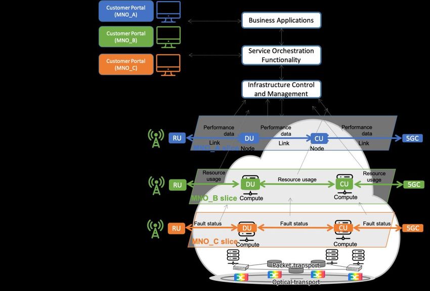
Disclaimer

© MEF Forum 2020. All Rights Reserved.

The information in this publication is freely available for reproduction and use by any recipient
and is believed to be accurate as of its publication date. Such information is subject to change
without notice and MEF Forum (MEF) is not responsible for any errors. MEF does not assume
responsibility to update or correct any information in this publication. No representation or
warranty, expressed or implied, is made by MEF concerning the completeness, accuracy, or
applicability of any information contained herein and no liability of any kind shall be assumed by
MEF as a result of reliance upon such information.

The information contained herein is intended to be used without modification by the recipient or
user of this document. MEF is not responsible or liable for any modifications to this document
made by any other party.

The receipt or any use of this document or its contents does not in any way create, by implication
or otherwise:

      a) any express or implied license or right to or under any patent, copyright, trademark or
         trade secret rights held or claimed by any MEF member which are or may be associated
         with the ideas, techniques, concepts or expressions contained herein; nor

      b) any warranty or representation that any MEF members will announce any product(s)
         and/or service(s) related thereto, or if such announcements are made, that such
         announced product(s) and/or service(s) embody any or all of the ideas, technologies, or
         concepts contained herein; nor

      c) any form of relationship between any MEF member and the recipient or user of this
         document.

Implementation or use of specific MEF standards, specifications, or recommendations will be
voluntary, and no Member shall be obliged to implement them by virtue of participation in MEF
Forum. MEF is a non-profit international organization to enable the development and worldwide
adoption of agile, assured and orchestrated network services. MEF does not, expressly or
otherwise, endorse or promote any specific products or services.

 MEF         © MEF Forum 2020. Any reproduction of this document, or any portion thereof, shall contain the following
             statement: "Reproduced with permission of MEF Forum." No user of this document is authorized to modify any
 2020033
             of the information contained herein.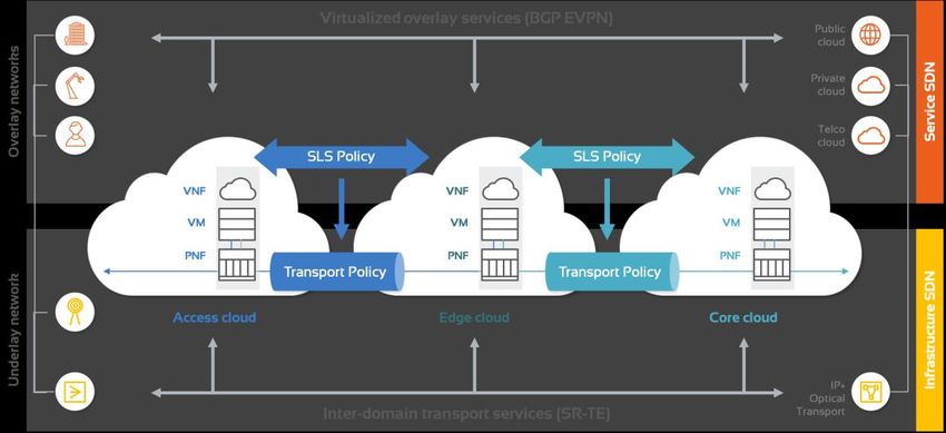
Slicing for Shared 5G Fronthaul and Backhaul

                                                          Table of Contents
1         Abstract................................................................................................................................ 1
2         Introduction ......................................................................................................................... 2
3         Market Trends and Business Drivers ............................................................................... 3
4         Mobile Networks and MEF LSO ....................................................................................... 5
    4.1      5G Mobile Network Architecture ...................................................................................... 5
    4.2      Network Sharing for 5G .................................................................................................... 6
    4.3      Network Slicing for 5G ..................................................................................................... 8
    4.4      Network Slicing vs Network Sharing for 5G Mobile Transport ....................................... 8
    4.5      MEF LSO ........................................................................................................................ 10
5         Network Sharing and Slicing for 5G Use Cases based on MEF 3.0 standards ........... 11
    5.1      Network Sharing Use Cases for 5G Mobile Transport .................................................... 12
      5.1.1        Mobile Transport with Point-to-Point Connectivity Services ............................................... 12
      5.1.2        Mobile Transport with Multipoint-to-Multipoint Connectivity Services .............................. 13
      5.1.3        Mobile Transport with Multipoint-to-Point Connectivity Services ....................................... 13
      5.1.4        Mobile Transport with Multi-Layer Connectivity Service .................................................... 15
    5.2      Network Slicing Use Cases for 5G Mobile Transport ..................................................... 15
      5.2.1        Mobile Transport Network Slice Configuration Scenarios ................................................... 16
      5.2.2        Mobile Transport Slice Management..................................................................................... 17
    5.3      LSO Orchestration of Transport Slices ........................................................................... 19
      5.3.1        Creation of MFH Transport Slices......................................................................................... 20
      5.3.2        Creation of MBH Transport Slices ........................................................................................ 20
      5.3.3        Visualization and SLS Monitoring of Transport Slices ......................................................... 21
      5.3.4        Creation of New or Additional MBH Connectivity Triggered by New Core VNF............... 21
      5.3.5        Creation of New or Additional MBH Connectivity Triggered by Core Optimization .......... 21
      5.3.6        Cloud interconnect automation creating transport connectivity for 5G network slices......... 21
6         Ongoing MEF Developments for Network Sharing and Slicing for 5G ...................... 22
7         Summary............................................................................................................................ 23
8         About MEF ........................................................................................................................ 24
9         Terminology....................................................................................................................... 24
10        References .......................................................................................................................... 25
11        Acknowledgements ........................................................................................................... 27

MEF                © MEF Forum 2020. Any reproduction of this document, or any portion thereof, shall contain the following             Page iii
                   statement: "Reproduced with permission of MEF Forum." No user of this document is authorized to modify
2020033
                   any of the information contained herein.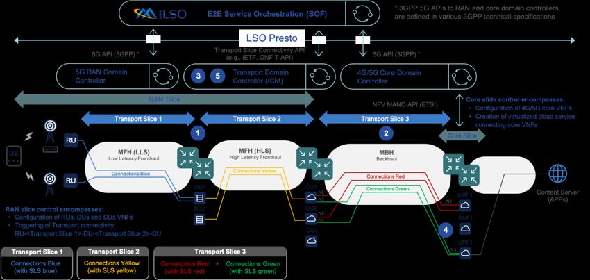
Slicing for Shared 5G Fronthaul and Backhaul

                                                         List of Figures
Figure 1 Network sharing agreements announced between 2010 and 2017 .................................. 4
Figure 2 Network sharing cost reduction estimates ........................................................................ 4
Figure 3 Example mobile network architecture evolution from 4G to 5G .................................... 5
Figure 4 5G RAN base station functional blocks and split options ................................................ 5
Figure 5 Some options for the gNB functional separation ............................................................. 6
Figure 6 Mobile network sharing models ....................................................................................... 7
Figure 7 Network sharing without slicing ...................................................................................... 9
Figure 8 Network sharing with slicing............................................................................................ 9
Figure 9 MEF LSO Reference Architecture ................................................................................. 10
Figure 10 MEF services supporting 5G network .......................................................................... 11
Figure 11 Point-to-point mobile transport use case ...................................................................... 13
Figure 12 Multipoint-to-multipoint mobile transport use case ..................................................... 14
Figure 13 Multipoint-to-point mobile transport service ............................................................... 14
Figure 14 Multi-layer mobile transport service ............................................................................ 15
Figure 15 Mobile transport network slice configuration scenarios .............................................. 17
Figure 16 Mobile transport network slice management scenarios................................................ 18
Figure 17 E2E 5G services support using 3GPP and MEF LSO .................................................. 20
Figure 18 Example of SLS adherence using cloud interconnect automation ............................... 22

                                                          List of Tables
Table 1 Terminology..................................................................................................................... 25

 MEF             © MEF Forum 2020. Any reproduction of this document, or any portion thereof, shall contain the following       Page iv
                 statement: "Reproduced with permission of MEF Forum." No user of this document is authorized to modify
 2020033
                 any of the information contained herein.
Slicing for Shared 5G Fronthaul and Backhaul

1   Abstract

This White Paper introduces the concept of 5G mobile access network sharing and use cases for
providing multiple mobile access network services over a common underlying fronthaul and
backhaul infrastructure. The use cases are described in the context of current MEF Services and
the MEF Lifecycle Service Orchestration (LSO) reference architecture. The target audience for
this White Paper includes fixed access line (fiber/copper) Service Providers and Mobile Network
Operators (MNOs).

 MEF        © MEF Forum 2020. Any reproduction of this document, or any portion thereof, shall contain the following   Page 1
            statement: "Reproduced with permission of MEF Forum." No user of this document is authorized to modify
 2020033
            any of the information contained herein.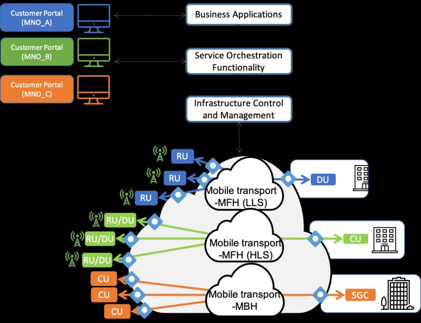
Slicing for Shared 5G Fronthaul and Backhaul

2   Introduction

Mobile Network Operators (MNOs) around the globe have started transitioning from 4G to 5G
infrastructure. However, rollout of 5G access infrastructure requires very large investments by
MNOs, for example: spectrum licensing, right-of-way for cell tower placement, cell towers and
associated equipment. Substantial investment is also required to build out or use networks suitable
for connecting the 5G radio access network (RAN) functional elements. This White Paper refers
to these networks as mobile transport networks; fronthaul and backhaul are special terms for
connectivity between specific parts of the 3GPP 5G network. To enable faster 5G network build-
out, MNOs are developing new business models based on mobile network sharing and network
slicing.

With revenue from services providing full or partial 5G mobile network sharing and slicing, MNOs
can accelerate their return on investment for existing infrastructure and speed up the build-out of
new infrastructure for areas where they do not have coverage.

Network slicing can enable the sharing of 5G RAN functional elements and the transport network.
When referring to the combination of 5G network functional elements and the transport network,
this White Paper uses the term “mobile transport”.

This White Paper provides Communications Service Providers (CSPs), MNOs and eventually
private 5G mobile network operators (verticals) with an overview of the current status of the
mobile access standards (including 4G and 5G) relating to data transport for fronthaul and
backhaul as well as use cases with MEF standards and studies that support 5G mobile transport.

The main focus of this White Paper is sharing mobile transport for both fronthaul and backhaul.

 MEF        © MEF Forum 2020. Any reproduction of this document, or any portion thereof, shall contain the following   Page 2
            statement: "Reproduced with permission of MEF Forum." No user of this document is authorized to modify
 2020033
            any of the information contained herein.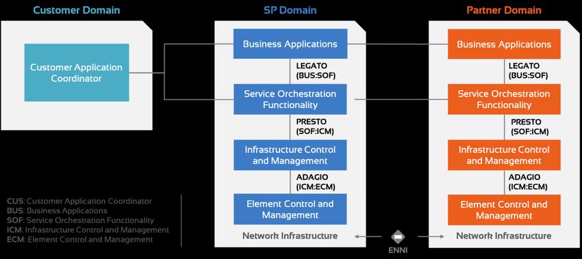
Slicing for Shared 5G Fronthaul and Backhaul

3   Market Trends and Business Drivers

5G is, in many cases, being deployed in parallel with 4G – which is still growing. In some cases,
sites will be purely 5G through, for example, the addition of small cells for increased capacity.
Typically, in a 3G or 4G service environment, MNOs own the infrastructure for their mobile
networks. In cases where MNOs do not have their own footprint, network sharing agreements
between MNOs are used to cover the respective mobile network area. In cases where MNOs do
not have their own mobile transport facilities, they use transport network services from local
transport Service Providers.

Therefore, with the advent of 5G and the densification of sites to meet capacity and coverage, the
interest in network sharing is growing. Network sharing agreements refer to the sharing of passive
and/or active components of networks owned by different operators. These components include
infrastructure such as towers and ducts, 5G RAN functional elements, transport networks, spectra
and core networks.

In addition to MNOs, companies in vertical industries can operate 5G spectrum and offer services.
These business entities may also use network sharing to complete the coverage areas for their
services.

To enable 5G services such as enhanced Mobile BroadBand (eMBB), massive Machine Type
Communications (mMTC) and Ultra-Reliable and Low Latency Communications (URLLC), 5G
RANs have been designed with a far larger number of base stations when compared to 4G service
footprints (cell site densifications). A 5G base station uses higher spectral bands with less favorable
propagation than a 4G base station, though with much higher capacity. A 5G base station also has
a much smaller range than a 4G base station, consequently more 5G cells are needed to cover the
same service area. Higher cell density means relatively higher deployment costs for the 5G MNO
building its own access infrastructure.

McKinsey & Company’s research shows that this is driving an important market for 5G access
services where the 5G access infrastructure is shared. Sharing is enabling a faster return on
investment for the owner of the 5G access infrastructure, much faster rollout of 5G services and
larger footprints for the MNOs [13].

Figure 1 is from the report from GSMA [10] on network sharing. It shows that network sharing
has become common since 2010. Like previous generations of network sharing, 5G network
sharing can be further adapted to support competing or different needs. Examples of such
adaptations are variations in the depth of sharing (small cell versus 5G Internet of Things macro
layer) and using different network sharing models for competitive urban markets and rural areas.
Customizing networks to specific situations allows MNOs with different needs to achieve new
savings.

Figure 2 is from a McKinsey & Company report [13]. It shows that for a 5G RAN standalone
deployment, the Total Cost of Ownership (TCO) increases by 86% compared to current (4G)
deployments. It also shows that if MNOs use network sharing, the TCO of the 5G RAN
deployment could be only a 57% increase over the current spending practice, significantly less
than the 86% increase without network sharing.

 MEF         © MEF Forum 2020. Any reproduction of this document, or any portion thereof, shall contain the following   Page 3
             statement: "Reproduced with permission of MEF Forum." No user of this document is authorized to modify
 2020033
             any of the information contained herein.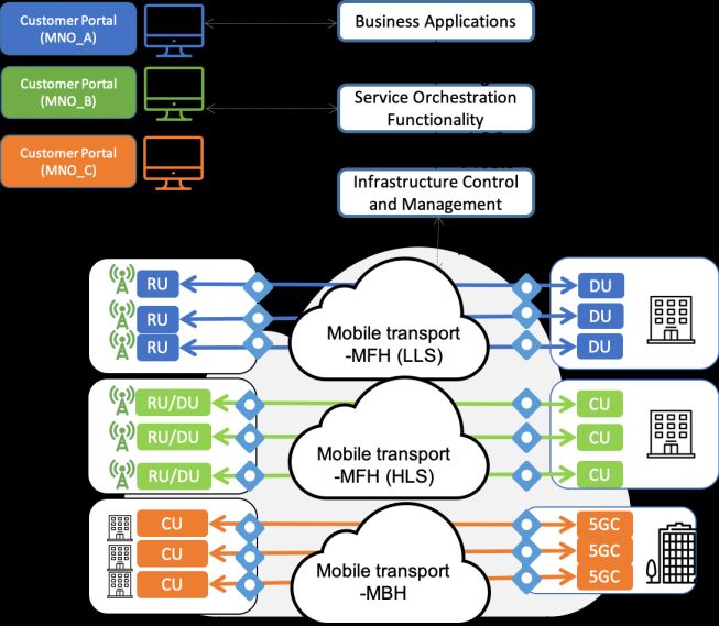
Slicing for Shared 5G Fronthaul and Backhaul

  Figure 1 Network sharing agreements                             Figure 2 Network sharing cost reduction
   announced between 2010 and 2017                                              estimates
          (Sources: GSMA Intelligence                                          (Source: McKinsey analysis
     https://www.gsma.com/futurenetworks/                                      https://www.mckinsey.com/)
   McKinsey analysis https://www.mckinsey.com/)

MEF        © MEF Forum 2020. Any reproduction of this document, or any portion thereof, shall contain the following   Page 4
           statement: "Reproduced with permission of MEF Forum." No user of this document is authorized to modify
2020033
           any of the information contained herein.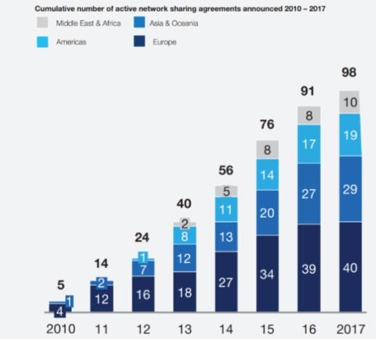
Slicing for Shared 5G Fronthaul and Backhaul

4     Mobile Networks and MEF LSO

This section starts with an introduction of current mobile network architecture, with the focus on
5G RAN functional elements and the mobile transport network. Subsections follow explaining 5G
network sharing with an introduction to network slicing and its benefits and an introduction of the
MEF Lifecycle Service Orchestration (LSO) reference architecture.
4.1     5G Mobile Network Architecture

Figure 3 shows examples of 4G and 5G mobile network
architectures. The 4G mobile network in this example
consists of Evolved Packet Core (EPC), Baseband Unit
(BBU) and Remote Radio Head (RRH). The common
public radio interface (CPRI) is used on the links
comprising the transport network connecting the BBU
and RRH; MEF refers to this transport network as
‘mobile fronthaul’ (MFH). The interface between the
EPC and BBU is termed S1. The supporting transport
network implementation is frequently referred to as
‘mobile backhaul’ (MBH).

In the evolution from 4G to 5G shown in Figure 3, the
main change in the RAN is that the original BBU function
in 4G/LTE is split into three units: a centralized unit
(CU), a distributed unit (DU) and additional functionality
at the radio unit (RU). The interface between the RU and
the DU is commonly referred to as eCPRI. The interface
between the DU and the CU is called F1. MEF terms the
transport network implementing these two interfaces as
the MFH. The new design allows RAN virtualization, with          Figure 3 Example mobile network
flexible assignment of computing resources across three architecture evolution from 4G to 5G
functional network entities to better meet the latency demands of new 5G services.
                                                 Option 1      Option 2          Option 3           Option 4       Option 5           Option 6           Option 7           Option 8
A 3GPP study concluded
that functional split Option
2 would be used for F1,                    RRC          PDCP             H-RLC              L-RLC          H-MAC              L-MAC              H-PHY              L-PHY              RF

which is called High Layer
Split (HLS) [6], as shown in
Figure 4. Low Layer Split                  RRC          PDCP             H-RLC              L-RLC          H-MAC              L-MAC              H-PHY              L-PHY              RF
(LLS) Options 7 and 8
correspond to the use of                                              High Layer Split (HLS)                              Low Layer Split
                                                                                                                                                                               ‘Legacy’ CPRI
                                                                  •     F1/W1                                             • Main sub-option: 7.2a, (eCPRI)
eCPRI        and      CPRI,
respectively.                Figure 4 5G RAN base station functional blocks and split options

 MEF        © MEF Forum 2020. Any reproduction of this document, or any portion thereof, shall contain the following                                                              Page 5
            statement: "Reproduced with permission of MEF Forum." No user of this document is authorized to modify
 2020033
            any of the information contained herein.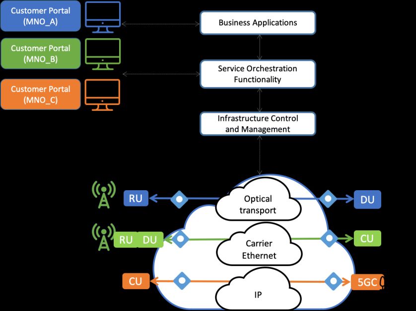
Slicing for Shared 5G Fronthaul and Backhaul

The interfaces for HLS and              Central RAN        Split RAN    Dual Split RAN       Cell site RAN
                                            (LLS)            (HLS)          (HLS+LLS)        (monolithic)
LLS differ in several
aspects, such as bandwidth                   CU
                                                               CU               CU
requirements,        latency
tolerance, functionality and                 DU
                                                       Edge
                                                       site
                                                                       Edge
                                                                       site
complexity of RU, as                  Edge
                                      site                                   F1                       F1

discussed in the study by
3GPP and O-RAN [21].                      RU
                                              RU
                                                              DU
                                                    RU
HLS (Option 2) requires                                                                            CU
                                            Cell site                           DU
less bandwidth and tolerates                              RU
                                                              RU
                                                                    RU             Agg. site
                                                                                                  DU
higher latency than LLS                                     Cell site

(Option 7 or Option 8). LLS        Latency tolerant                        RU                 RU
                                                                                RU                 RU
benefits from simpler and          Low latency                                        RU                RU
                                                                              Cell site         Cell site
cost-efficient RUs and
offers better possibilities
                               Figure 5 Some options for the gNB functional separation
for            centralized
aggregation and capacity integration.

Disaggregation of the 5G base station (gNB) functional entities and the corresponding MFH
interfaces give operators new opportunities to place the functions in separate physical locations
according to their priorities. Figure 5 presents several options for placement of these functions at
a cell site, at an aggregation site that is traditionally used for transport aggregation, or at an edge
site. The choice of option depends on several factors such as transport network topology,
availability of sites, latency and capacity limitations, as well as the availability of compute
resources.

A MEF MFH service can provide transport connectivity at the Option 2 (F1), Option 7 (eCPRI),
or Option 8 (legacy CPRI) split points. In addition, MEF defined the MEF MBH service for the
connectivity between a BBU and EPC and between a CU and 5G core (5GC) [15][16].

4.2      Network Sharing for 5G

Network sharing in mobile networks has been common since the introductions of 3G and 4G. The
reasons to share mobile networks include reduction in the cost of coverage per operator and
customer satisfaction. Network sharing is a rational approach that can help reduce costs, maximize
efficiency and enhance customer satisfaction.
Figure 6 shows a range of mobile network sharing models. 3GPP standards fully support network
sharing between operators in different scenarios such as Multi Operator Radio Access Network
(MORAN) and Multi Operator Core Network (MOCN) [1]. In these models, generally called RAN
sharing, base stations, RUs, DUs, CUs and the associated transport networks are shared among
MNOs (such as MNOs A and B in Figure 6). Mobile transport sharing is a model in which MNOs
lease transport network connectivity from transport Service Providers for their MBH/MFH.
Another model is where an MNO’s whole network is shared, including the mobile core and RAN,
with Mobile Virtual Network Operators (MVNOs).

 MEF          © MEF Forum 2020. Any reproduction of this document, or any portion thereof, shall contain the following   Page 6
              statement: "Reproduced with permission of MEF Forum." No user of this document is authorized to modify
 2020033
              any of the information contained herein.
Slicing for Shared 5G Fronthaul and Backhaul
Mobile MVNO
No sharing RAN sharing transport
MORAN based MOCN based sharing
MVNO MVNO
5GC
A B A B A B A B Shared
Core
MBH A B Shared Shared Shared Shared
CU A B Shared Shared A B Shared
MFH A B Shared Shared Shared Shared
(HLS)
DU A B Shared Shared A B Shared
RAN
MFH
A B Shared Shared Shared Shared
(LLS)
RU A B Shared Shared A B Shared
Spectrum A B A B Shared A B Shared
Figure 6 Mobile network sharing models
The mobile transport network is a key component for implementing mobile network sharing, as it
is necessary for all models of sharing. MBH sharing has been common in many countries using
4G and will continue to be so in the era of 5G. On the other hand, legacy MFH LLS networks
cannot be shared because they are implemented either with direct fibers or with wavelength
division multiplexing (WDM) equipment for CPRI/OBSAI. In these networks the traffic occupies
a dark fiber or a single wavelength of a WDM system. In 5G, MFH LLS networks will be sharable
because eCPRI requires less bandwidth and is more latency tolerant than legacy CPRI.
Furthermore, MFH HLS networks (Option 2) require less bandwidth and tolerate higher latency
than LLS. This enables Service Providers to offer MFH services over shared networks as is
currently the practice for MBH services.
MEF has developed implementation guidelines for mobile transport services which can be offered
over shared mobile transport networks [14]. A MEF Service Provider may provide transport
network services for MBH and/or MFH to multiple customers, i.e., MNOs. MEF standards play a
significant role in network sharing for 5G mobile transport. Specifically, MEF standards can be
useful in the following mobile transport network sharing scenarios:
1. Service Provider providing MBH and MFH services for multiple MNOs
2. MNO sharing its transport network with other MNOs
MEF © MEF Forum 2020. Any reproduction of this document, or any portion thereof, shall contain the following Page 7
statement: "Reproduced with permission of MEF Forum." No user of this document is authorized to modify
2020033
any of the information contained herein.Slicing for Shared 5G Fronthaul and Backhaul
4.3 Network Slicing for 5G
Network slicing is a means for a Service Provider (or any network operator) to create independent,
isolated logical networks within its common or shared network infrastructure. These network slices
can be offered externally to customers or used internally by the Service Provider. A Service
Provider can use network slicing to structure and organize the elements of its infrastructure, i.e.,
the capabilities and functionality exposed and their management, providing self-contained units
(network slices) of varying sizes and complexity.
5G network slicing first emerged in the MNO domain and received additional attention when the
NGMN 5G Vision White Paper was published in 2015 [19]. Many standards organizations —
3GPP being a prominent one — began work on the topic. Examples of other standards
organizations with related activities are BBF, ETSI ISG NFV, GSMA, IEEE, IETF, and ITU-T.
In addition to standards organizations, some open source communities, such as ONAP and OSM,
are addressing the issue of implementing network slicing.
A 5G network slice, as defined by the 3GPP, is inherently an end-to-end concept used to connect
the mobile user’s equipment to tenant-specific applications (which may reside in public or private
clouds). Within end-to-end 5G network slices, transport slices are created as independent logical
networks that enable multiple tenants on each single physical infrastructure supporting the
connectivity path. From a customer perspective, transport slices offer improvement in service
flexibility/customization and deterministic service level specifications (SLSs) that can be strictly
enforced (for example, to meet traffic engineering requirements for bandwidth, low latency, high
availability).
Besides the focus on mobile networks — especially mobile transport in this White Paper — the
5G and network slicing concept has wider applicability. However, the terms ‘network slicing’ or
‘network slice’ are not always used in those broader contexts (for example, an alternative is ‘virtual
network’). The common concept is logical customized networks over a common infrastructure
used to provide flexible solutions for different market scenarios. The scenarios have diverse
network requirements with respect to functionality, performance and resource allocation.
4.4 Network Slicing vs Network Sharing for 5G Mobile Transport
This section presents the additional benefits of network slicing over and above those of network
sharing.
Figure 7 shows the traditional network sharing model without network slicing. In this model,
MNO_A and MNO_B share a physical mobile transport network, which is owned by a third party
transport Service Provider or either one of the two MNOs. MNO_A and MNO_B directly control
and manage each node and link for configuration and monitoring. Configuration and management
actions of both MNOs must be carried out in a tightly coordinated manner because an operation
by one MNO can affect the other MNO’s services as a result of their sharing the same physical
infrastructure. To avoid possible service quality degradation, a contract or agreement between
MNO_A and MNO_B and strict compliance are necessary.
As shown in Figure 8, network sharing with slicing enables sharing of the physical mobile
transport network via the provisioning of dedicated virtual networks for MNO_A and MNO_B.
MEF © MEF Forum 2020. Any reproduction of this document, or any portion thereof, shall contain the following Page 8
statement: "Reproduced with permission of MEF Forum." No user of this document is authorized to modify
2020033
any of the information contained herein.Slicing for Shared 5G Fronthaul and Backhaul
These virtual networks are independent and isolated from each other even though they share the
same physical mobile transport network, owned either by MNO_A, MNO_B or a third party
transport Service Provider. Each MNO arranges a contract with the owner of the physical transport
network for dedicated virtual networks as slices. Therefore, a sharing contract or agreement
between MNO_A and MNO_B is no longer necessary since they each have independent control
and management of their respective virtual networks. In other words, network slicing enables
network sharing with independent operation and management by the MNOs.
Figure 7 Network sharing without slicing
Figure 8 Network sharing with slicing
MEF © MEF Forum 2020. Any reproduction of this document, or any portion thereof, shall contain the following Page 9
statement: "Reproduced with permission of MEF Forum." No user of this document is authorized to modify
2020033
any of the information contained herein.Slicing for Shared 5G Fronthaul and Backhaul
4.5 MEF LSO
Network automation with MEF LSO helps reduce management complexity so that operators can
achieve the speed and efficiency they need to make 5G network slicing economical. According to
Bell Labs, automated networks will see a 30% decrease in operational costs versus the present
mode of operations used in traditional WANs [7].
MEF LSO provides APIs to automate the entire lifecycle of services orchestrated across multiple
provider networks and multiple technology domains within a provider network [17]. The LSO
reference architecture, shown in Figure 9, characterizes the management and control domains (e.g.,
SP and Partner) and functional management entities (e.g., Business Applications) that enable inter-
provider orchestration. The architecture also identifies the management interface reference points
(e.g., LSO Sonata) which are the logical points of interaction between specific functional
management entities. These management interface reference points are further defined by interface
profiles and implemented as APIs. Note that this is a functional architecture and does not describe
how the functional management entities are implemented (e.g., single vs. multiple instances), but
rather identifies functional management entities that provide logical functionality as well as the
points of interaction among them.
Figure 9 MEF LSO Reference Architecture
In LSO, services are orchestrated by a Service Provider across all internal and external network
domains from one or more network operators. These network domains may be operated by, among
others, CSPs, data center operators, enterprises, wireless network operators, virtual network
operators, and content providers. LSO spans in a federated approach all those network domains
that require coordinated management and control to deliver end-to-end services.
The LSO Cantata interface is used for business-related interactions such as ordering and billing
between the Customer and the Service Provider, and LSO Sonata is used for similar business-
related interactions between Service Providers.
MEF © MEF Forum 2020. Any reproduction of this document, or any portion thereof, shall contain the following Page 10
statement: "Reproduced with permission of MEF Forum." No user of this document is authorized to modify
2020033
any of the information contained herein.Slicing for Shared 5G Fronthaul and Backhaul
The LSO Allegro interface is used for configuration and control-related management interactions
that are allowed by the respective service agreement such as operational state queries, request up-
dates to service parameters, or requests to instantiate other services.
The LSO Presto interface is used for orchestrating within the Service Provider domain at the
network level and the LSO Adagio interface correspondingly orchestrates at the resource level.
According to MEF 55, both these interfaces allow for APIs that are used for the purpose of
orchestrating compute resources in parallel to other resources.
5 Network Sharing and Slicing for 5G Use Cases based on MEF 3.0 standards
In this section, network sharing and slicing for 5G use cases show how standardized MEF 3.0
Services apply. MEF Services supporting 3GPP 5G networks help MNOs implement their RAN
by providing mobile transport and potentially the RAN itself as a virtual network.
The first mobile transport use cases focus on network sharing and slicing in a 5G RAN, i.e., MEF
Services supporting 3GPP 5G networks. They show how MEF 22.3 [15] and MEF 22.3.1 [16]
provide the MFH or MBH connectivity services to implement a RAN and the importance of LSO
in the orchestration, control and management of mobile transport networks.
Figure 10 illustrates the business relationship where MNOs are the Customers who order mobile
transport services from the transport network provider. The transport network provider implements
LSO interfaces for service ordering and intra-provider service orchestration (not shown), then
creates MFH (LLS), MFH (HLS), or MBH connectivity according to the MNOs’ orders. In parallel,
MNOs configure mobile network functions such as RUs, DUs, CUs, and 5G cores using their
internal interfaces. By connecting these mobile network functions to mobile transport services,
MNOs can build their mobile networks using a shared transport network.
Mobile Network OperatorE-2-E LSO Transport Network Provider
LSO
Mobile Domain
Interfaces Transport Domain
Orchestration Orchestration
MFH MBH
RF MFH
Service
UE RU DU CU CORE
(RRU) (BBU)
Network
Resource RAN
Figure 10 MEF services supporting 5G network
MEF © MEF Forum 2020. Any reproduction of this document, or any portion thereof, shall contain the following Page 11
statement: "Reproduced with permission of MEF Forum." No user of this document is authorized to modify
2020033
any of the information contained herein.Slicing for Shared 5G Fronthaul and Backhaul
Other use cases introduce network slices for RAN sharing. These are based on different business
models in which MNOs (Customers) buy either an entire mobile transport or RAN components
provided as dedicated virtual networks (network slices) from a Service Provider. As MNOs will
require orchestration, configuration and management capabilities for their virtual networks, these
may be provided through LSO interfaces.
5.1 Network Sharing Use Cases for 5G Mobile Transport
The transport network is one of the largest investments for an MNO as it typically requires wireline
connectivity between communication sites. For that reason, MBH sharing is already an established
practice for previous generations of mobile service. Similarly for 5G, the key to making more
investment savings in mobile transport for 5G is the sharing of MFH in addition to MBH while
meeting the different requirements of MNOs with different types of connectivity and SLSs.
An MNO can use MEF Services to provide connectivity for its 3GPP RAN and core network (CN).
MEF 22.3 [14] specifies the requirements for Carrier Ethernet Services and external interfaces
(such as Ethernet UNI and ENNI) for MBH connections and MEF 22.3.1 [16] specifies the
requirements for MFH (both HLS and LLS) connections.
Therefore, by using MEF 22.3 and MEF 22.3.1, mobile transport for MFH and MBH can be
implemented with an industry-standard service. These standards are beneficial for both Service
Providers and their Customers (MNOs). On the one hand Service Providers are afforded new
revenue-generating opportunities to provide MFH services to MNOs in addition to MBH services.
On the other hand, Customers (MNOs) can reduce their capital investment in MFH.
In this section, use cases based on MEF 22.3, MEF 22.3.1 and relevant standards for mobile
transport services are presented. The mobile transport Service Provider can use network slicing of
its infrastructure to create one transport network slice per MNO.
As summarized in a previous study [6], performance requirements for MFH (LLS and HLS) and
MBH are different in terms of latency, bandwidth and synchronization. In general, MFH (LLS)
has stringent quality requirements to support the eCPRI interface. MFH (HLS) is less strict for
latency and bandwidth compared with MFH (LLS). MBH also has different characteristics and
requirements. Service Providers need to take into account these differences in providing mobile
transport services to their Customers.
5.1.1 Mobile Transport with Point-to-Point Connectivity Services
Figure 11 shows a simple use case of a mobile transport service. MNOs as Customers can choose
from three types of connectivity services based on MEF standards, and are able to create, modify,
and monitor the respective types of connectivity through LSO APIs.
The Customer (MNO_A) shown in blue requests MFH (HLS) from a Service Provider for the
point-to-point connectivity between an RU and DU; the Customer (MNO_B) shown in green
requests MFH (LLS); and the Customer (MNO_C) shown in orange requests MBH.
MEF © MEF Forum 2020. Any reproduction of this document, or any portion thereof, shall contain the following Page 12
statement: "Reproduced with permission of MEF Forum." No user of this document is authorized to modify
2020033
any of the information contained herein.Slicing for Shared 5G Fronthaul and Backhaul
Figure 11 Point-to-point mobile transport use case
This point-to-point connectivity can be implemented with an Ethernet Private Line (EPL) Service
(MEF 6.2 [14]) — the connectivity service between two UNIs.
5.1.2 Mobile Transport with Multipoint-to-Multipoint Connectivity Services
Figure 12 presents another use case of a mobile transport service. Multipoint-to-multipoint service
is used where each MNO needs separated connections between multiple pieces of equipment at a
radio site and multiple entities at a local/aggregation site.
As shown in figure 12, the Customer (MNO_A) shown in blue has multiple RUs at a cell site and
corresponding DUs at a local site. Every connectivity between RUs and DUs is independent and
should not be aggregated to ensure the MFH (LLS) latency and bandwidth requirements are met.
The Customer (MNO_B) shown in green has dedicated MFH (HLS) connectivity services for all
combinations between DUs and corresponding CUs. The Customer (MNO_C) shown in orange
has MBH connectivity services for all combinations between CUs and corresponding 5GCs.
Multipoint-to-multipoint mobile transport service enables MNOs to connect multiple entities
between two sites with dedicated connectivity. It can also be implemented using EPLs for mesh
connectivity.
5.1.3 Mobile Transport with Multipoint-to-Point Connectivity Services
Figure 13 presents a general use case for MNOs. The traffic from a cell site or local site often
aggregates at another site. The connectivity between multiple local sites and aggregation sites can
also be implemented with a MEF Service.
In this figure, the Customer (MNO_A) in blue has MFH (LLS) connectivity between multiple RUs
at different sites and a single DU at a local site. The Customer (MNO_B) in green has MFH (HLS)
connectivity between multiple DUs at different sites and a single CU at an aggregation site. The
MEF © MEF Forum 2020. Any reproduction of this document, or any portion thereof, shall contain the following Page 13
statement: "Reproduced with permission of MEF Forum." No user of this document is authorized to modify
2020033
any of the information contained herein.Slicing for Shared 5G Fronthaul and Backhaul
Customer (MNO_C) in orange has MBH connectivity between multiple CUs in different sites and
a single 5GC.
Figure 12 Multipoint-to-multipoint mobile transport use case
Figure 13 Multipoint-to-point mobile transport service
The connectivity described above can be implemented with an EVPL Service. MNOs can benefit
from MEF standardized services and interface attributes for mobile transport services and the LSO
automation benefits of on-demand creation and management of mobile transport services.
MEF © MEF Forum 2020. Any reproduction of this document, or any portion thereof, shall contain the following Page 14
statement: "Reproduced with permission of MEF Forum." No user of this document is authorized to modify
2020033
any of the information contained herein.Slicing for Shared 5G Fronthaul and Backhaul
5.1.4 Mobile Transport with Multi-Layer Connectivity Service
As described in Section 4.1, mobile transport networks differ in their level of requirements for
connectivity quality, such as latency, bandwidth and availability. To satisfy these requirements,
MNOs can choose to create connectivity at the optimal transport layer.
Figure 14 presents the use case for multi-layer mobile transport services. The Customer (MNO_A)
shown in blue requests optical transport connectivity for MFH (LLS) to connect a RU with a DU.
The Customer (MNO_B) shown in green requests Carrier Ethernet connectivity for MFH (HLS)
to connect a DU and CU. The Customer (MNO_C) shown in orange requests an IP service for the
MBH to connect the CU and 5GC.
MEF standards have been defined for these multi-layer connectivity services and can be applied
to mobile transport connectivity to satisfy SLS requirements. LSO APIs are also available to
orchestrate these multi-layer connectivity services.
Figure 14 Multi-layer mobile transport service
5.2 Network Slicing Use Cases for 5G Mobile Transport
This section presents network slicing use cases for mobile transport. In these use cases, three
MNOs use services from the same Service Provider of mobile transport connectivity connecting
each MNO’s respective RUs/DUs/CUs to their corresponding DUs/CUs/5GCs. The Service
Provider applies network slicing to its shared mobile transport network creating three network
slices that include compute resources for deploying CU/DU functions — one slice per MNO: blue,
green, orange. These three network slices are constructed on common infrastructure, with mobile
transport network management enforcing their isolation.
The Service Provider provides each of its customers with network service and visibility into the
network slice serving that customer’s connections. The customers are able to perform certain
MEF © MEF Forum 2020. Any reproduction of this document, or any portion thereof, shall contain the following Page 15
statement: "Reproduced with permission of MEF Forum." No user of this document is authorized to modify
2020033
any of the information contained herein.Slicing for Shared 5G Fronthaul and Backhaul
configuration and management activities, which are described in subsections 5.2.1 and 5.2.2 in
different scenarios. Figures in these subsections show MNO_A and the corresponding Service
Provider network slice MNO_A slice shown in blue; MNO_B and the corresponding Service
Provider network slice MNO_B slice shown in green; MNO_C and the corresponding Service
Provider network slice MNO_C slice shown in orange.
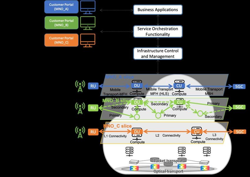
5.2.1 Mobile Transport Network Slice Configuration Scenarios
To obtain a network connecting their radio locations to the co-location site, MNOs use a network
service from a Service Provider. The network service exposes a network for creating connections
and computes resources for deploying functions.
5.2.1.1 VNF Deployment
In Scenario 1 in Figure 15, the Customer (MNO_A) shown in blue uses its network service for
deploying DUs/CUs and connections between them. MNO_A requests network functions such as
DUs and CUs to be deployed to a specific compute node in the exposed network. It can request
the instantiation of MFH (LLS) connections between RUs and DUs, MFH (HLS) connections
between DUs and CUs, and MBH connections between CUs and 5GC. Although CUs and DUs
are used as examples for network functions for simplicity in this scenario, other network functions
are also possible, such as security and QoS control functions.
5.2.1.2 Topology and Redundancy Configuration
Many MNOs want to configure the primary and secondary path themselves for low latency or high
availability. Scenario 2 in Figure 15 illustrates a topology and redundancy configuration scenario
of MNO_B slice for mobile transport. In this scenario, the Customer (MNO_B) shown in green is
provided another network service by the Service Provider and it configures redundant paths as a
combination of Ethernet Virtual Connections (EVC) for mobile transport connections. In this
scenario, MNO_B requests connections to a DU from an RU through a specific link or node to
minimize latency or implement redundancy for connectivity. For the connections between a DU
and CU or between a CU and 5GC, MNO_B requests specific routes for latency or redundancy
requirements.
5.2.1.3 Multi-Service
MNOs themselves need to ensure sufficient performance quality for mobile transport and cost
reductions by network sharing, while guaranteeing SLS. Therefore, multi-layer connectivity
configuration and control are essential. Scenario 3 in Figure 15 illustrates configuring multi-layer
connectivity in a network slice for mobile transport. In this scenario, the Customer (MNO_C)
shown in orange requests L1 connectivity service for MFH (LLS), Ethernet L2 connectivity
service for MFH (HLS) and L3 connectivity service for MBH.
MEF © MEF Forum 2020. Any reproduction of this document, or any portion thereof, shall contain the following Page 16
statement: "Reproduced with permission of MEF Forum." No user of this document is authorized to modify
2020033
any of the information contained herein.Slicing for Shared 5G Fronthaul and Backhaul
Figure 15 Mobile transport network slice configuration scenarios
5.2.2 Mobile Transport Slice Management
In addition to configuration, management is also important for mobile transport slices because
mobile transport needs to satisfy strict SLSs regarding latency, jitter and bandwidth. In this section,
three scenarios regarding mobile transport slice management are presented.
5.2.2.1 Performance Monitoring
Scenario 1 in Figure 16 illustrates the performance monitoring of a mobile transport slice. Through
LSO APIs, the Customer (MNO_A) shown in blue configures a mobile transport network using a
dedicated service provided by a Service Provider. Performance data, such as latency, for each
connection/link is reported for the service to MNO_A. MNO_A monitors service performance and
confirms that it satisfies the SLS requirements.
5.2.2.2 Resource Monitoring
Scenario 2 in Figure 16 illustrates resource monitoring of a mobile transport slice. The Customer
(MNO_B) shown in green monitors network or compute resource usage, such as traffic volumes
per link for transport resources and CPU/memory usage for compute resources. Resource
monitoring is necessary for MNOs to keep mobile transport quality stable and optimize
network/compute resources.
MEF © MEF Forum 2020. Any reproduction of this document, or any portion thereof, shall contain the following Page 17
statement: "Reproduced with permission of MEF Forum." No user of this document is authorized to modify
2020033
any of the information contained herein.Slicing for Shared 5G Fronthaul and Backhaul
5.2.2.3 Fault Monitoring
Scenario 3 in Figure 16 illustrates fault monitoring of a mobile transport slice. In this scenario,
the Customer (MNO_C) shown in orange uses a network service as a mobile transport slice.
MNO_C monitors the states of links and nodes in MNO_C slice to obtain information about fault
location, recovery and history enabling it to locate any causes of failure and to take remedial action.
Figure 16 Mobile transport network slice management scenarios
MEF © MEF Forum 2020. Any reproduction of this document, or any portion thereof, shall contain the following Page 18
statement: "Reproduced with permission of MEF Forum." No user of this document is authorized to modify
2020033
any of the information contained herein.Slicing for Shared 5G Fronthaul and Backhaul
5.3 LSO Orchestration of Transport Slices
LSO orchestration of transport slices is an important factor to consider in the context of supporting
3GPP 5G network slices.
Although the primary focus of this White Paper is network sharing and slicing for MFH and MBH,
it is worth considering how LSO-based orchestration can be applied beyond MFH and MBH. This
serves the aim of Service Providers to automate the service lifecycles and maximize the
coordination of 5G services orchestration, management and control across all 5G mobile network
domains (RAN, transport and core).
3GPP specifies standards for 5G mobile networks and mobile network slicing. In the following
use cases, MEF LSO functions are correlated to 3GPP network slice and subnetwork slice
management functions as follows:
• The MEF end-to-end Service Orchestration Function (SOF) is referenced by 3GPP as the
E2E Network Slice Management Function (NSMF)
• MEF network domain controllers for RAN, transport and core network domains which
provide Infrastructure Control and Management functions (ICM) are referenced by 3GPP
as the Network Slice Subnet Management Function (NSSMF)
3GPP has defined the interfaces for the NSMF to communicate with both the RAN NSSMF and
core NSSMF. However, 3GPP has not, as yet, defined the same interface for the transport domain.
In this use case the MEF LSO Presto interface reference point (SOF:ICM) is applicable for the
NSMF to communicate with the transport NSSMF.
In support of services on 3GPP-defined 5G E2E network slices, transport slices provide the
corresponding mobile transport networks. These enable consistent operational practices and
automation on less complex networks, thus accelerating service delivery.
Transport slices also enable different endpoints with specific SLSs to be connected using a
multitude of types of shared or dedicated network resources with differing levels of isolation.
There is a need for flexibility in implementing transport slices to support the delivery of 5G
services across mobile transport networks consisting of products from multiple vendors, multiple
domains and using various transport network technologies, tunnel types (e.g., ODU/OCh, Ethernet,
IP, MPLS, segment routing) and MEF Service types (e.g., Optical transport, Carrier Ethernet, IP
VPN). This implementation flexibility enables support for a wide range of E2E 5G deployment
scenarios and use cases, including for 4G/5G hybrid networks.
For example, in Figure 17, a single Service Provider is both the MNO and the transport network
provider. The E2E 5G network deploys an E2E network slice composed of a RAN subnetwork
slice, three transport slices and a core subnetwork slice. The transport slices enable the transport
connectivity between network elements in the RAN and core subnetwork slices across low latency
MFH (LLS) (slice 1 with blue connections), high latency MFH (HLS) (slice 2 with yellow
connections) and MBH (slice 3 with red and green connections). Transport slicing may also be
applied from the 5G core to public networks or clouds.
MEF © MEF Forum 2020. Any reproduction of this document, or any portion thereof, shall contain the following Page 19
statement: "Reproduced with permission of MEF Forum." No user of this document is authorized to modify
2020033
any of the information contained herein.Slicing for Shared 5G Fronthaul and Backhaul
Figure 17 E2E 5G services support using 3GPP and MEF LSO
for mobile transport domain use cases
The E2E network slice is orchestrated by the E2E Service Orchestration (SOF) using the RAN,
core and transport domain controllers (ICMs) via APIs at the MEF LSO Presto interface reference
point. The domain controllers can expose APIs at LSO Presto that can be implemented compatibly
with relevant standards (e.g., 3GPP, ETSI-NFV, IETF, ONF T-API [20], MEF NRM [18]).
Figure 17 shows possible MEF LSO-related use cases for the 5G transport domain described in
the following sub-sections.
5.3.1 Creation of MFH Transport Slices
In this use case (blue circle #1 in Figure 17), LSO Presto APIs are used to create two transport
slices connecting the fronthaul RUs to DU1 (Transport slice 1) and DUs to CUs (Transport slice
2).
The 3GPP 5G API supports the creation of the RAN slice where the 5G RAN domain controller
(ICM) configures the RUs, as well as the DU and CU VNFs, which then triggers the creation of
the RAN transport connectivity (i.e., RU – Transport slice 1 – DU – Transport slice 2 – CU) by
the transport domain controller (ICM).
5.3.2 Creation of MBH Transport Slices
In this use case (blue circle #2 in Figure 17), LSO Presto APIs are used to create a transport slice
connecting the RAN to the core (Transport slice 3).
The 3GPP 5G API and ETSI NFV MANO API [9] support the creation of the core slice where the
5G core domain controller (ICM) configures the 4G/5G core VNFs, which then triggers the
creation of the virtualized cloud services connectivity which connects the 4G/5G core VNFs. In
MEF © MEF Forum 2020. Any reproduction of this document, or any portion thereof, shall contain the following Page 20
statement: "Reproduced with permission of MEF Forum." No user of this document is authorized to modify
2020033
any of the information contained herein.Slicing for Shared 5G Fronthaul and Backhaul
this case, once the core slice has been created, the E2E Service Orchestration (SOF) triggers the
transport domain controller to connect the RAN slice to the core slice.
5.3.3 Visualization and SLS Monitoring of Transport Slices
In this use case (blue circle #3 in Figure 17), visualization and SLS monitoring of transport slices
1, 2 and 3 are achieved through exposure to the E2E service orchestrator via LSO Presto APIs.
Once transport slices 1, 2, 3 have been created, the transport domain controller (ICM) is then able
to streamline and automate the visualization and SLS monitoring of transport slices by exposing
its transport slice connectivity data model to the E2E Service Orchestration (SOF).
5.3.4 Creation of New or Additional MBH Connectivity Triggered by New Core VNF
In this use case (blue circle #4 in Figure 17) that builds on the use case depicted as blue circle #2,
the creation of a VNF instance in the core triggers via inter-domain (east-west) operational
functionalities the creation in the transport domain of additional backhaul connectivity (Transport
slice 3) to the RAN slice, after which the E2E service orchestrator is notified via LSO Presto APIs.
5.3.5 Creation of New or Additional MBH Connectivity Triggered by Core Optimization
In this use case (blue circle #5 in Figure 17) that builds on the use case depicted as blue circle #4,
a core VNF being moved due to core slice optimization (i.e., after a core slice SLS violation)
automatically triggers the required additional connectivity.
This same use case could be used within a RAN if, for example, the CU VNF is moved due to a
RAN slice optimization (i.e., after a RAN slice SLS violation), where the moved CU VNF now
requires fronthaul connectivity to a DU.
5.3.6 Cloud interconnect automation creating transport connectivity for 5G network slices
A key use case for 5G mobile network slicing is that of cloud interconnect automation, where the
deployment of VNF instances can dynamically establish transport connectivity (using appropriate
transport slices) to connect the core and RAN slices. In this use case, where a virtual 5G RAN or
5G core is within an edge cloud or central cloud, the data center gateway (see an example
visualized in Figure 18) is a delineation point between the transport domain and the virtual
network. The use of signaling protocols, supported by the data center gateway, is one method of
implementing cloud interconnect automation to dynamically trigger the creation of transport
connectivity for specific VNFs (that will be a part of a core or RAN slice). This type of cloud
interconnection automation enables a transport domain controller (ICM) to coordinate across
domains to achieve deterministic SLSs across E2E virtual and physical network resources.
The mapping of a transport slice SLS policy to specific transport network policy colors is one
approach for cloud interconnect automation to implement closed-loop adherence for pre-
determined SLSs (which for 5G transport slicing can be designed by the operator to support a
specific type of slice). For example, in Figure 18, cloud interconnection automation can be used
for a BGP EVPN virtualized overlay service over Segment Routed Traffic Engineered (SR-TE)
inter-domain transport services. In this example, the transport slice SLS policy gets mapped to SR-
TE policies between access and edge clouds, as well as edge cloud and core cloud.
MEF © MEF Forum 2020. Any reproduction of this document, or any portion thereof, shall contain the following Page 21
statement: "Reproduced with permission of MEF Forum." No user of this document is authorized to modify
2020033
any of the information contained herein.You can also read