Axial fans/Jet fans AXC, AXCBF, AXR, AXS, AJR, AJ8 - Installation and Operating Instructions GB - Products
←
→
Page content transcription
If your browser does not render page correctly, please read the page content below
Axial fans/Jet fans
AXC, AXCBF, AXR, AXS, AJR, AJ8
Installation and Operating Instructions   GB

Document in original language | · 008
© Copyright Systemair AB
All rights reserved
E&OE

Systemair AB reserves the rights to alter their products without notice.
This also applies to products already ordered, as long as it does not affect the previously agreed specifications.

                                                                                                                     | 008
Contents
1 General information .........................................1 7.3 Installation jet fans ............................... 18
1.1 Warning symbols ...................................1 7.3.1 Deflector ................................ 19
1.1.1 Instruction symbols.....................1 8 Electrical connection ...................................... 19
2 Important safety information .............................1 8.1 Protecting the motor............................. 19
2.1 Personnel .............................................2 8.2 Connection ......................................... 20
2.2 Personal protective equipment..................2 8.2.1 Terminal box .......................... 20
2.3 5 rules of electrical safety ........................2 8.2.2 Wiring diagram ........................ 21
3 Warranty .......................................................2 8.3 Frequency converter (if used) ................. 21
4 Delivery, transport, storage ...............................2 9 Commissioning ............................................. 22
4.1 Delivery ...............................................3 9.1 Tests ................................................. 22
4.2 Transport. .............................................3 9.2 Commissioning of speed-controlled
4.3 Storage ................................................3 fans .................................................. 22
5 Description ....................................................4 9.3 Adjusting the blade angle....................... 22
10 Operation .................................................... 22
5.1 General ................................................4
5.1.1 Fan and motor data ....................4 11 Troubleshooting/maintenance/repair ................ 23
5.1.2 Temperature types .....................4 11.1 Troubleshooting ................................... 23
5.1.3 Air gap between housing and 11.2 Maintenance ....................................... 24
impeller ...................................5 11.3 Variable-speed fans.............................. 25
5.2 Description axial fans (AXC, AXR, 11.4 Overhaul/further maintenance ................ 25
AXS)....................................................5 11.5 Spare parts ......................................... 26
5.2.1 Construction..............................6 12 Cleaning ...................................................... 26
5.2.2 Types & variants ........................6 13 Deinstallation/dismantling............................... 26
5.2.3 Accessories...............................7 14 Disposal ...................................................... 26
5.3 Description Jet fans .................................8 15 Commissioning Report.................................... 27
5.3.1 Description AJR/AJ8 ....................8
5.4 Description AXCBF ..................................9
5.4.1 Construction............................ 10
5.5 Intended use ...................................... 11
6 Name plate and type key ................................ 12
7 Installation................................................... 13
7.1 Vibration dampers ................................ 14
7.2 Installation positions ............................. 15
7.2.1 Installation of the ventilation
system .................................. 16
7.2.2 Installation of flexible
connections ............................ 17
7.2.3 Installation silencer ................... 18
7.2.4 (K), (B), (F)— fans — special
points .................................... 18
7.2.5 Air gap................................... 18
| 008General information | 1
1 General information
1.1 Warning symbols
Danger Caution
Direct hazard Hazard with a low risk
Failure to comply with this warning will lead Failure to comply with this warning may lead to
directly to death or to serious injury. moderate injuries.
Warning Important
Potential hazard Hazard with risk of damage to objects
Failure to comply with this warning may lead to Failure to comply with this warning will lead to
death or serious injury. damage to objects.
Note:
Useful information and instructions
1.1.1 Instruction symbols
Instruction Instruction with fixed sequence
♦ Carry out this action 1. Carry out this action 3. (if applicable, further actions)
2. Carry out this action
♦ (if applicable, further actions)
2 Important safety information
Planners, plant builders and operators are responsible for the proper assembly and intended use.
♦ Read the operating instructions completely and carefully.
♦ Keep the operating instructions and other valid documents, such as the circuit diagram or motor instructions, with
the fan. They must always be available at the place of use.
♦ Observe and respect local conditions, regulations and laws.
♦ Abide by the system-related conditions and requirements of the system manufacturer or plant constructor.
♦ Safety elements may not be dismantled, circumvented or deactivated.
♦ Only use the fan in operational condition, if in doubt contact Systemair.
♦ Provide generally prescribed electrical and mechanical protective devices.
♦ During installation, electrical connection, commissioning, troubleshooting, and maintenance, secure the location and
premises against unauthorised access.
♦ Do not circumvent any safety components or put them out of action.
♦ Keep all the warning signs on the fan complete and in a legible condition.
♦ The device is not to be used by persons (including children) with reduced physical, sensory or mental capabilities, or
lack of experience and knowledge, unless they have been given supervision or instruction.
♦ Do not allow children to play with the device.
| 0082 | Warranty
2.1 Personnel
The fan may only be used by qualified, instructed and trained personnel. The persons must know the relevant safety di-
rectives in order to recognise and to avoid risks. The individual activities and qualifications can be found in Table 1 Qual-
ifications, page 2.
Table 1 Qualifications
Activities Qualifications
Storage, operation, transport, cleaning, disposal Trained personnel (see following note)
Electrical connection, commissioning, electrical Electrical expert or matching qualification
disconnection
Installation, disassembly Fitter or matching qualification
Electrical expert or matching Fitter or matching
Maintenance
qualification qualification
Electrical expert or matching Fitter or matching
qualification qualification
Repair
Smoke extraction fans and EX fans only by agreement with
Systemair.
Note:
The operator is responsible for ensuring that personnel are instructed and have understood the contents of
the operating instructions. If something is unclear, please contact Systemair or its representative.
2.2 Personal protective equipment
♦ Wear protective equipment during all work in the vicinity of the fan.
• protective working clothes • protective working gloves • goggles
• protective working shoes • helmet • hearing protection
2.3 5 rules of electrical safety
1. Disconnect (disconnection of 2. Prevent reactivation 4. Ground and short-circuit
the electrical system from 3. Test absence of voltage 5. Cover or restrict adjacent live parts
live components at all
terminals)
3 Warranty
For the assertion of warranty claims, the products must be correctly connected and operated, and used in accordance
with the data sheets. Further prerequisites are a completed maintenance plan with no gaps and a commissioning re-
port. Systemair will require these in the case of a warranty claim. The commissioning report is a component of this
document. The maintenance plan must be created by the operator, see section 11.2 Maintenance.
4 Delivery, transport, storage
Safety information
Warning: Risk from rotating fan blades
♦ Prevent access by unauthorised persons by safety personnel or access protection.
Warning: Suspended loads
♦ Wear protective equipment during all work in the vicinity of the fan, details see 2.2 Personal protective equipment,
page 2.
♦ Do not walk under suspended loads.
♦ Make sure that there is nobody under a suspended load.
| 008Delivery, transport, storage | 3
4.1 Delivery
Each fan leaves our plant in an electrically and mechanically proper condition. We recommend transporting the fan to
the installation site in the original packaging.
Checking delivery
♦ Check the packaging and the fan for transport damage. Any findings should be noted on the cargo manifest.
♦ Check completeness of the delivery.
Unpacking
Warning
When opening the transport packaging, there is a risk of damage from sharp edges, nails, staples,
splinters etc.
♦ Unpack the fan carefully.
♦ Check the fan for obvious transport damage.
♦ Only remove the packaging shortly before assembly.
♦ Wear protective equipment during all work in the vicinity of the fan, details see 2.2 Personal protective
equipment, page 2.
4.2 Transport
Safety information
Warning: Electrical or mechanical hazards due to fire, Caution: If transported without care during loading and
moisture, short circuit or malfunction. unloading, the fan may be damaged.
♦ Never transport the fan by the connecting wire, ♦ Load and unload the fan carefully.
terminal box, impeller, protection grille, inlet cone or ♦ Use hoisting equipment that is suitable for the weight
silencer. to be hoisted.
♦ In open transport, please make sure that no water can
♦ Observe the transportation arrows on the packaging.
penetrate into the motor or other sensitive parts.
♦ Use the fan packaging exclusively as transport
♦ We recommend transporting the fan to the protection and not as a lifting aid.
installation site in the original packaging.
4.3 Storage
Safety information Preconditions
♦ Store the devices in a clean, dry and vibration-free
Warning: Risk of injury and damage to the fan.
environment.
♦ Do not stack the fans on top of one another.
♦ Storage temperature should be between –20°C and
♦ Do not use transport packaging as hoisting aids. 60°C.
♦ Use hoisting equipment that is suitable for the weight
to be hoisted.
Storage more than 3 months Storage more than 12 months
♦ Turn the impeller at least 10 revolutions once a ♦ We recommend an inspection by the after-sales
month. service of Systemair before commissioning.
♦ Please ensure that the impeller is at a different
position afterwards.
| 0084 | Description
5 Description
5.1 General
• The fan conveys air in an axial direction from the intake side via the electric motor to the outlet side. (except AXCBF).
• The electrical connection is made through a terminal box installed on the outside of the housing (except AXCBF).
Sensors (optional)
Sensors can be connected to the fan to monitor the roller bearings and for vibration monitoring.
Standstill heating (optional)
The standstill heating starts when the motor switches off and vice versa.
5.1.1 Fan and motor data
• The technical data of the fan can be seen on the name plate or the data sheet.
• The motor data can be found on the name plate of the motor or in the technical documents of the motor
manufacturer.
• The data on the name plate of the fan apply to "standard air" according to ISO 5801.
5.1.2 Temperature types
Table 2 Types of fans
Long-term Long-term
Diameter (B) 300°C/ (F) 400°C/
Type operation operation
[mm] 120 min. 120 min.
–20°C...55°C -20°C...200°C
AXC1/AXR/AXS 315 — 1600 X
AXCBF 250— 800 X X
AXC (B)1/AXR (B) 315 — 1600 X X
AXC (F)1AXR (F) 315 — 1600 X X
AJR/AJ8 315 — 400 X
AJR (B)/AJ8 (B) 315 — 400 X X
AJR (F)/AJ8 (F) 315 — 400 X X
1 also —P, —PV and —G
| 008Description | 5
5.1.3 Air gap between housing and impeller
AXC (K)
AXC (B)
AXC
AXR (K) AXC (K)-P AXC (F)
AXR
AXR (B) AXC (B)-P AXR (F) AXC (F)-P
AXC-P
AJR (K) AXC (K)-PV AJR (F) AXC (F)-PV
AJR
AJR (B) AXC (B)-PV AJ8 (F)
AJ8
AJ8 (K)
AJ8 (B)
Standard
temperature
Hous- Air gap Air gap Air gap Air gap Air gap
ing
Size Poles
toler- min max min max min max min max min max
ance
315 2–pol 1 1 3 2 3,5 2 4 4 6 - -
355 2–pol 1 1 3 2 3,5 2 4 4 6 - -
400 2–pol 1 1 3 2 3,5 2 4 4,5 6 - -
450 2–pol 1 1 3 3 4,5 2,5 4,5 6 6,5 3 5
500 2–pol 1 1 3 3 4,5 2,5 4,5 5 7 3 5
560 2–pol 1 1 3 4 5,5 2,5 4,5 6 8 3,5 5,5
630 2–pol 1 1 3 4 5,5 2,5 4,5 7 9 3,5 5,5
4–pol 2,5 4,5 3,5 5,5
710 1 1 3 4 5,5 7 9
2–pol 4 6 - -
4–pol 3,5 5,5 4 6
800 1 1 3 5 6,5 8 10
2–pol 5 7 - -
900 4–pol 1 1 3 5 6,5 3,5 5,5 9 11 4 6
1000 4–pol 2 2 5 5 7 4 7 10 12 5 8
1120 4–pol 2 2 5 6,5 8,5 4 7 11,5 14
1250 4–pol 2 5 7 9 4,5 7,5 12,5 15
1400 4–pol 2 6 9 7,5 9,5 14 16
1600 4–pol 3 7 10 8 11,5 16 18
1800 4–pol 4 10 14 11,5 15,5 18 21
2000 4–pol 4 10 14 11,5 15,5 20 23
2240 4–pol 5 12 16 13 18,5 0 0
5.2 Description axial fans (AXC, AXR, AXS)
• For B3 conventional motors, the motor bracket is made from galvanized steel sheet. B30 “pad mounted” motors are
fitted in the housing via threaded rods or a welded motor support.
• The motor with impeller is mounted to a sturdy supporting structure.
| 0086 | Description
5.2.1 Construction
6
1
3
4
2
7
5
1 Motor 3 Terminal box 5 Mounting feet
2 Impeller 4 Housing 6 Motor brackets
7 Guide vane only available for -PV version
5.2.2 Types & variants
Table 3 Axial fan base types
Type Description
AXC Standard fan of the AXC-series. As a default, the fans are provided in protection class IP55,
ISO F.
AXS Special fans for marine, oil and gas applications.
AXR The conveying direction can be reversed by switching the direction of rotation.
Table 4 Axial fan variants
Type Description
-P Fan of AXC-series which uses impeller design of the "-P" generation.
Fan of AXC-series which uses impeller design of the "-P" generation and includes bolt on
-PV
guide vane.
-Box Fan of AXC-series inside a sound-insulated box.
-G Fans constructed as garage version. Arrangement of two fans in series, switched behind
one another.
(B) Smoke extract fan suitable for 2 hours at 300°C. As a default, the fans are provided in
protection class IP54/55, ISO H. The connection wire from the motor to the terminal box is
protected via an additional flexible metal hose. The standard motors (400 V type B3) are
without motor protection.
(F) Smoke extract fan suitable for 2 hours at 400°C. As a default, the fans are provided in
protection class IP54/55, ISO H. The connection wire from the motor to the terminal box is
protected via an additional flexible metal hose. The standard motors (400 V type B3) are
without motor protection.
-SC Short Casing.
| 008Description | 7
5.2.3 Accessories
Horizontal installation
1 6 7
2
3
4 8
5
13
14
15
8
9
10/11
Vertical Installation 1 SG/SG-20* Protection guard
2 ESD-F Inlet cone
3 RSA Silencer
14 4 EV, EVH Flexible connection
(F400)
5 MPR Mounting ring from size 315 to 1000
13
6 REV (60°C) Isolator switch
7 REV (fire Isolator switch
rated)
8 MP Mounting bracket from size 1120
6
9 MFA Mounting foot
10 SD Rubber anti-vibration mounts
5 11 FSD Spring anti-vibration mounts
12 ZSD/HNG Suspension spring anti-vibration mounts/Rubber-
11 metal damper for mounting on the ceiling
13 LRK Air operated damper
4
14 GFL Counter flange
15 ABS Outlet cowl
3 Note:
• Some accessories are also available for jet fans and AXCBF,
please check our online catalogue or contact Systemair.
• *The distance between safeguard SG-20 and the impeller
must be ≥ 850 mm according to ISO 13857.
2
1
| 0088 | Description
5.3 Description Jet fans
5.3.1 Description AJR/AJ8
• In B3 conventional motors, the motor bracket is made from galvanized steel sheet. B30 “pad mounted” motors are
fitted in the housing via threaded rods or a welded motor support.
• The fan conveys air in an axial direction from the intake side via the electric motor to the outlet side.
• The silencers are equipped with protection grille made of galvanized steel.
• The acoustic insulation is non-flammable in accordance with DIN 4102 as described in directive 97/69 EC.
Table 5 Constructive features
AJR/AJ8 As a default, the fans are provided in protection class IP55, ISO F.
As a default, the fans are provided in protection class IP54/55, ISO H. The wiring from
AJR (K)/AJ8 (K)/AJR (B)/AJ8
the motor to the terminal box is protected via an additional flexible metal hose. The
(B)/AJR (F)/AJ8 (F)
standard motors (400 V type B3) are without motor protection.
5.3.1.1 Construction
AJ8
5
7 6
2 1
6
5 4 3 AJR
7
5
6
1
2
4 3
5 6
1 Motor 4 Housing 7 Mounting bracket
2 Impeller 5 Protective guard
3 Terminal box 6 Silencer
| 008Description | 9
Table 6 Dimensions AJ8, AJR
L F
211 E
AJR
H
F
B
F
L B
211 E
AJ8
H
Size H [mm] B [mm] E [mm] F [mm] L [mm]
AJ8 315 (B), (F) 365 375 325 678 1535
AJ8 355 (B), (F) 395 400 355 678 1695
AJ8 400 (B), (F) 445 500 460 727 1875
ARJ 315 (B), (F) 365 223 265 433 1535
ARJ 355 (B), (F) 465 243 305 473 1695
ARJ 400 (B), (F) 505 266 350 516 1875
5.4 Description AXCBF
Directly powered axial fan with motor outside the air flow. The fan can be run in permanent operation up to a conveying
media temperature of 200°C. Maximum ambient temperature 55°C. Housing flanges on both sides with bores accord-
ing to eurovent 1/2 standard. B3 conventional motors with add-on terminal box.
| 00810 | Description
5.4.1 Construction
1 Motor
2 Impeller
3 Housing
1
4 Motor
bracket
4
2
3
Table 7 Dimensions
Size 250 — 500 Size 630 — 800
F
½I A H ½I
A H I
I
D
C
D
C
F
B
Size A ØB ØC ØD ØF ØH I
[mm]
AXCBF 250 535 448 328 250 280 10 4x90°
AXCBF 315 535 452 385 320 355 10 8x45°
AXCBF 400 625 585 480 401 450 10 8x45°
AXCBF 500 660 695 590 504 560 12 12x30°
AXCBF 630 790 728 634 - 690 12 12x30°
AXCBF 800 880 890 797 - 860 12 16x22.5°
| 008Description | 11
5.5 Intended use
All axial fans
• The temperature of the air transported through the fan must not exceed the temperature range stated on the
name plate.
• For the temperature resistance of the smoke extraction fans (K), (B), (F), which can also be used to extract CO,
please refer to the name plate (e.g. 300°C/120 min).
Jet fans Axial fans
• AJ8 and AJR jet fans are intended for installation in • The axial fans of the series AXC/AXR/AXCBF in the
underground and above-ground parking structures, to versions G (K), (B), (F) are intended for installation in
facilitate ventilation and smoke extraction (K), (B), (F). ventilation systems.
• For optimum operation, the jet fan must be • The axial fans of the series AXC/AXR/AXCBF are
suspended horizontally from the ceiling in such a ready-to-use products and are used as components
position that intake and outlet are unobstructed. for ventilation devices, machines and systems. These
fans can be used to extract, draw in or convey air.
• The fans can be installed both in duct systems and
also with free suction via an inlet cone and a suction-
side contact protection grille. Free discharge via a
contact protection grille is also possible.
Incorrect use
Incorrect use refers mainly to using the fan in another way to that described. The following examples are incorrect and
hazardous:
• The fan is not suitable for intake of aggressive media or media with a dust content so high that dust deposits on the
impeller or fan housing can affect the operation of the fan.
• The fan must not be installed in hazardous areas (areas with a potentially explosive atmosphere).
• The motors cannot be voltage controlled.
| 00812 | Name plate and type key
6 Name plate and type key
3
EN 12101-3 (2015)
Powered Smoke and Heat Control ventilator
Type: AXC 355-6/10°-2(B)-P
Stage 1 of 2
1 General data
Order no. / Production no.: 0003500662 / 1251364 1
Manufacturing date: 06/2021
Made in: Germany 2 Technical data
Voltage: 400V Y
Frequency: 50 Hz
Nominal power at shaft (P2): 0,75 kW IE3 Temp./Time information/
Nominal current: 1,66 A
3 only listed on smoke
Cos φ: 0,79
2
Insulation class: H extraction fans
Protection class, motor: IP55
Fan impeller speed: 2865 1/min
Weight: 38 kg
Max. temperature of transported air: 55°C - 300°C/2h 4 ErP data
Number of certification: 2797 CPR 719672
3
Number of certification UK: 0086 CPR 719672
Values for the single fan unit at power efficiency optimum Certifications and QR—
determined without speed control 5
: 32,4 % Pitch angle: 20° Codes
V: 3.218 m³/h psf: 332 Pa
4
P1: 0,92 kW RPM: 2.940
Measurement cat. / Efficiency cat.: A / Static
Efficiency grade: (N38) N=39,0
6 Manufacturer Address
* A variable speed drive must be installed with this fan!
5
This Powered Smoke and Heat Control ventilator shall be installed as per the manufacturer´s instruction.
Installation and Operating Instructions are within the delivery.
Systemair GmbH - Seehöfer Straße 45 - 97944 Boxberg - Germany 6
Table 8 Type key
AXC 355 -6 /10° -2 (-)(K), (B), (F) P —
• C — counter-rotating
• V — guide vane
• G — Garage
• A — Low pressure impeller
• P — plus (new impeller generation)
Temperature- Time information (smoke
extraction fan), see 5.1.2 Temperature types,
page 4
Number of poles
Blade angle
Number of blades
Nominal diameter of the fan
AXC Axial fan
AXR Axial fan — reversible
AXS Axial fan — ship
AJR Circular jet fan
AJ8 Octagonal jet fan
AXCBF Axial fan bifurcated
AXC-SC Axial fan-Short Case
| 008Installation | 13
7 Installation
Safety information
Danger: Risk that the fan does not work in case of fire.
♦ Use installation material with fire resistance classes that meet temperature requirements.
Warning: Danger from falling fan or fan parts.
♦ Check the surface before installation for load bearing capacity.
♦ Consider all static and dynamic loads when selecting hoisting equipment and fastening components.
General safety information
♦ Installation may only be carried out by adequately qualified persons, details see Table 1 Qualifications, page 2.
♦ Move the impeller of the fan by hand before you install it in order to check whether that moves freely.
♦ Prevent the possibility of foreign bodies being drawn in.
♦ To reduce transmission of vibration to the duct system, we recommend flexible connections from our accessory
range, see 5.2.3 Accessories, page 7.
♦ Bear in mind that parts of the impeller may protrude out of the fan housing.
♦ If the product is installed with free suction or free discharge, install a protection grille to prevent injury from the fan
impeller. Make sure that the safety distance agrees with the standards DIN EN ISO 13857 and DIN 24167–1.
♦ Tightening torques of screw-type connections according to DIN 13.
Preconditions
♦ Ensure that the fan and all its components are ♦ Ensure that the information on the name plates (fan
undamaged. and motor) matches up with the operating conditions.
♦ Ensure that there is enough space to install the fan. ♦ A warning sign must be attached close to the air
♦ Protect against dust and moisture when installing. outlet, stating that the air outlet must not be covered.
♦ Do not install the fan if the gap in the table (5.1.3 Air ♦ Fit the fans in such a way that there is sufficient
gap between housing and impeller, page 5) is not access for troubleshooting, maintenance and repair.
complied with.
Tests after long storage time (more than 12 months)
Note:
We recommend an inspection by the after-sales service of Systemair before commissioning.
Test the motor windings:
♦ Measure the insulation resistance of each motor winding against grounding at 500 V DC. The insulation resistance
must be > 10 mΩ.
Measures for an insulation resistance < 10 mΩ:
1. If the motor has drain plugs, remove them to allow any moisture to drain and replace them when the motor windings
are suitably dry.
2. Dry the motor in a warm dry airflow (typically 40 degrees Celsius).
3. Measure the insulation resistance of each motor winding against grouding at 500 V DC.
4. Repeat the aforementioned steps until the measurement outcome > 10 mΩ.
| 00814 | Installation
Mounting feet
Depending on the kind of fan and the construction size, mounting feet are either included in the delivery or available as
accessories. If you are not sure, check the online catalogue or contact Systemair.
Avoid resonance frequencies
Important
Risk of damage to the fan due to resonance frequencies
♦ The minimum fan speed should be double the resonance frequency of the anti-vibration system
(vibration dampers).
♦ To avoid resonance frequencies, see 8.3 Frequency converter (if used), page 21.
7.1 Vibration dampers
Important
Risk of damage to the fan due to incorrect vibration dampers
♦ Use the vibration dampers suitable for the respective weight.
♦ Use the vibration dampers with fire resistance classes that match the respective application.
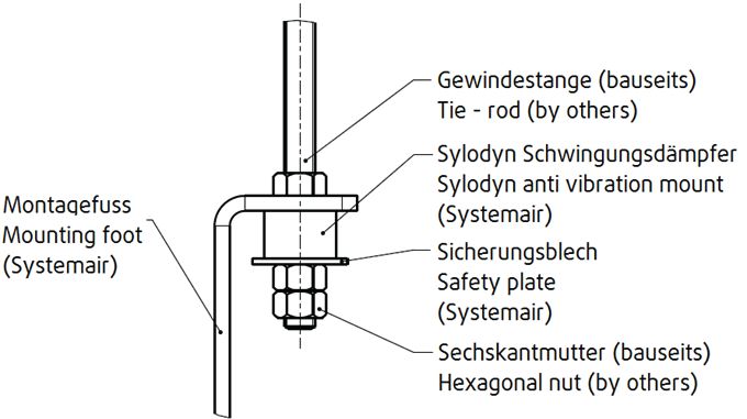
Sylodyn vibration kit (if used)
The responsibility for the Sylodyn vibration kit installation is with the buyer/installer.
Important
Risk of damage to the fan due to incorrect installed vibration dampers
♦ The fan shall rest entirely on the sylodyn anti vibration blocks. It is important that the fan is not pressed
against the mounting frame, therefore the minimum distance of 15 mm has to be kept, see following
picture.
1 Hexagonal head set screw
2 Sylodyn anti Available as Systemair accessory with a hole Ø
vibration block 16mm 6
3 Safety plate Available as Systemair accessory with a hole Ø
1
16mm
4 Hexagonal nut min. 15 mm 2
5 Mounting foot
6 Mounting frame 5
3
4
| 008Installation | 15
Lifting and positioning
The weight of the fan units varies depending on the motor size and accessories. As a result, the fan unit can also be
very bulky and heavy. You can find precise information on the name plate or the data sheet.
Caution
Risk of parts falling down
♦ When fitting the fan, pay attention to its weight and the weight of the components.
Lifting Positioning
♦ Lift the fan unit slowly and carefully. ♦ Observe the arrows on the name plate or the housing
of the fan. They show the direction of rotation and air
♦ Use hoisting gear permitted for the weight of the fan.
flow.
♦ Attach the hoisting equipment to flanges and foot
♦ Position the fan unit so that it is standing in the
bores or at the marked places.
planned direction of flow.
♦ Use transport equipment (e.g. lifting eyes) if available.
♦ Provide enough free space for inspection and
♦ Please observe the marking “oben/top” on the fan. maintenance work on the fan unit.
Anchor
♦ Use suitable fittings.
♦ If you are not sure, contact Systemair.
7.2 Installation positions
AXC, AXR, AXS
♦ Consider below guideline for installation positions.
Note:
• Order process (Systemair configurator): If the type of installation is e.g. "SO" (vertical installation, >= IEC
160), a suitable motor is automatically used (in this case with different bearings).
• Please contact Systemair if a position marked with a “red-cross” is required for an existing fan.
Fans equipped with
• B3 160
AXCBF
Important
Overheating motor
♦ The motor opening must be faced upwards to avoid trapped heat.
| 00816 | Installation
7.2.1 Installation of the ventilation system
Preconditions
♦ The air flow of the fan must be able to open the air operated damper (LRK).
Installation duct
♦ Do not place a duct bend directly 1
before or after the fan!
• This can cause damage to the
bearings or other parts of the fan.
• The duty point may not be min. 2,5xD
reachable.
• The fan may make noise.
3
♦ Ensure a direct, smooth and 2
constant air flow to the device.
Ensure a free exhaust, see the
following pictures.
♦ Install an inlet cone or a channel
section with a length of at least 2.5
x D. It is not recommended to install
the protective guard directly in
min. 2,5xD
front of the impeller (without inlet
cone), as additional noise and a
deterioration of the air
performance may result. 3
♦ To reduce transmission of vibration
to the duct system, we recommend 1 Inlet cone 2 Protective guard 3 Flexible connection
flexible connections from our
accessory range, see 5.2.3
Accessories, page 7.
D = nominal diameter
Distance from the wall/ceiling
♦ Ensure enough distance between the ceiling and the
wall.
• The duty point may not be reachable. 1xD
• The fan may make noise.
If the minimal distances are not possible for construction min. 1xD
reasons, install a deflector in front of the fan in a way
that ensures a direct, smooth and constant flow of air.
Contact with rotating parts must be ruled out at all times
– either by ducts of a corresponding length or by
protective grids.
D = Nominal diameter
| 008Installation | 17
7.2.2 Installation of flexible connections
Important
Increasing noise emission
♦ Do not install the flexible connections at an angle.
Note:
When fitting the flexible connections, make sure that
they are fitted according to the installation length
(Table 9 Flexible connections — Installation length,
page 17), without compression or tensile strain. They
must not be used to compensate any lack of precision
in the assembly.
Table 9 Flexible connections — Installation length
EV (-25...70°C) EVH (400°C/2h)
Size LB full LE LB Overall LE
length Installation length Installation
[mm] length [mm] [mm] length [mm]
315 157 (+/-5) LB — 10 147 (+/-5) LB — 10
355 157 (+/-5) LB — 10 147 (+/-5) LB — 10
400 157 (+/-5) LB — 10 147 (+/-5) LB — 10
450 157 (+/-5) LB — 10 147 (+/-5) LB — 10
500 157 (+/-5) LB — 10 147 (+/-5) LB — 10
560 157 (+/-5) LB — 10 147 (+/-5) LB — 10
630 157 (+/-5) LB — 10 147 (+/-5) LB — 10
710 157 (+/-5) LB — 10 147 (+/-5) LB — 10
800 157 (+/-5) LB — 10 147 (+/-5) LB — 10
900 157 (+/-5) LB — 10 147 (+/-5) LB — 10
1000 157 (+/-5) LB — 10 147 (+/-5) LB — 10
1120 157 (+/-5) LB — 15 147 (+/-5) LB — 15
1250 157 (+/-5) LB — 15 147 (+/-5) LB — 15 LB
1400 157 (+/-5) LB — 15 200 (+/-5) LB — 15
1600 157 (+/-5) LB — 15 200 (+/-5) LB — 15
| 00818 | Installation
7.2.3 Installation silencer
♦ Ensure correct installation of the silencer.
• This can cause damage to the bearings or other parts of the fan.
• The duty point may not be reachable.
• The fan may make noise.
♦ Ensure a direct, smooth and constant air flow to the device. Ensure a free exhaust, see the following pictures.
♦ To reduce transmission of vibration to the duct system, we recommend flexible connections from our accessory
range, see 5.2.3 Accessories, page 7.
Plenum box with not available as
1 perforated sheet Systemair
(flow straightener) accessory
not available as
Deflector with inner Systemair
2
core accessory
not available as
3 Baffles Systemair
accessory
available as
1
4
4 Flexible connection Systemair 5
accessory
available as
5 Flexible connection Systemair
accessory
6 Inlet cone available as
Systemair 2
accessory 3 6
7.2.4 (K), (B), (F)— fans — special points
Type Special points for assembly
AXC (B), (K), (F) Smoke exhaust fans are suitable for installation inside or outside a smoke reservoir, as well as
AXR (B), (K), (F) outdoors. If positioned outside the smoke reservoir, the fan must be provided with heat insulation
AXC-P (B), (F) by the customer. The heat insulation must be provided with fire proof material L120 according to
AXC-PV (B), (F) DIN 4102-4.
7.2.5 Air gap
Ensure that the air gap between the housing and the impeller is complied with.
♦ Contact Systemair ♦ Do not install the fan if the gap in the table is not
♦ Check if the air gap complies with the table.5.1.3 Air complied with.
gap between housing and impeller, page 5
7.3 Installation jet fans
Always install in a horizontal position.
| 008Electrical connection | 19
7.3.1 Deflector
For optimal guidance of the air current, a deflector made of galvanized steel sheet can be mounted on the pressure-
side silencer (accessory).
The deflector as accessory for AJR/AJ8 is delivered in a separate package.
♦ Before installing the jet fan, fasten the deflector on the silencer of the pressure side (see arrow).
♦ Position the deflector fins so that after fastening the jet fan to the ceiling, the air flow is directed downwards at a
10° angle. It may be possible to readjust the fans afterwards depending on the structures located in the immediate
vicinity, such as girders.
AJ8 AJR
Position the fins to the specified angle and secure them Fasten the deflector with an M6 x 40 screw, an M6 nut
with 4.2 x 13 self-drilling screws. Use M4 x 12 self- and a Ø6 serrated washer.
locking screws to fasten the deflector to the fan.
8 Electrical connection
Safety information
Warning: Danger from electrical voltage.
♦ Observe the 5 rules of electrical safety, see 2.3 5 rules of electrical safety, page 2.
♦ Prevent the ingress of water into the connection box.
♦ Electrical connection may only be carried out by adequately qualified persons, details see Table 1 Qualifications, page
2.
8.1 Protecting the motor
Important
Damage to motor due to overcurrent, overload or short circiut.
♦ Lead-out temperature monitors must be integrated in the control circuit in such a way that, if a fault
occurs, the motor cannot switch on again automatically after it has cooled down.
♦ Motor lines and temperature monitor lines should be laid separately on principle.
♦ Without thermal protection: Use a motor protection switch!
Important
Damage to motor due to over temperature.
♦ To avoid too many starts and stops a falling delay time of minimum 5 minutes has to be realized in the
control circuit.
| 00820 | Electrical connection
Table 10 Motor protection
Type Motor protection Thermal protection, Speed regulation
standard
Fans for long-term
operation —20 °
C...55 °C only, see By customer PTC Possible via frequency converter
5.1.2 Temperature
types, page 4
AXC (B),(F),(K)
AXR (B),(F),(K)
AXC (B)-P, (F)-P By customer- must be
without (PTC optional) Possible via frequency converter
AXC (B)-PV, (F)-PV bypassed in case of fire
AJ8 (B), (K), (F)
AJR (B), (K), (F)
8.2 Connection
♦ Check that the data on the name plate matches the ♦ Tighten all glands well in order to guarantee
connection data. protection class IP.
♦ Complete the electrical connection according to the ♦ Screw the lid of the terminal box/inspection switch
circuit diagram. evenly tight.
♦ Use all of the locking screws. ♦ Connect the cable end in a dry environment!
♦ Insert the screws by hand to avoid damaging the ♦ Install a circuit breaker in the permanent electrical
thread. installation, with a contact opening of at least 3 mm
at each pole.
Protective grounding wire
The protective grounding must have a cross-section equal to or greater than that of the phase conductor.
Residual current circuit breaker
All-current-sensitive residual current circuit breakers are required for use in alternating-current systems with 50/60
Hz, in combination with electronic devices such as EC motors, frequency converters or uninterruptible power supplies
(UPS).
Type Electrical Connection
AXC, AXR, AXS, AXC-P, AXC-
Connection via terminal box. The terminal box is fitted on the outside of the housing.
PV, AJR, AJ8
AXCBF Connection via terminal box. The terminal box is attached to the motor.
8.2.1 Terminal box
The below terminal boxes are used for fans up to a nominal current of 100 A. If the nominal current exceeds 100 A oth-
er terminal boxes are used.
• up to size* 900 • from size* 1000
• up to 63 A • up to 100 A
A: M16x1,5
A: M16x1,5
B: M40x1,5
B: M25x1,5
C: M50x1,5 A
A B B C
*nominal diameter of the fan
| 008Electrical connection | 21
8.2.2 Wiring diagram
Important
Wrong connection can damage or destroy the motor.
♦ Use the information on the nameplate to select the correct connection diagram.
Star / Delta Star / Delta
W2 U2 V2 W2 U2 V2
230 V 400 V
U1 V1 W1 U1 V1 W1
wiring_230/400V_180928_001
wiring_400/690V_190121_001
W2 U2 V2 W2 U2 V2
400 V 690 V
U1 V1 W1 U1 V1 W1
“1” — Δ “1” — Δ
“2” — Y “2” — Y
“3” — Thermal motor protection optional “3” — Thermal motor protection optional
Two seperate windings Dahlander
“1” — Connection for low speed “1” — Connection for low speed
“2” — Connection for high speed “2” — Connection for high speed
“3” — Thermal motor protection optional “3” — Thermal motor protection optional
8.3 Frequency converter (if used)
Risk from resonant frequencies when using frequency Commissioning of the frequency converter
converter.
♦ Install the fan and frequency converter as near as
♦ Only operate the fan outside these speed ranges. possible to one another.
♦ Pass through these speed ranges so quickly that any ♦ Use shielded cables.
vibration cannot exceed the admissible resonant ♦ All components (fan, frequency converter and motor)
frequency values. must be grounded.
♦ For variable-speed fans, use a permanent vibration ♦ We recommend using all-pole sinus filters.
monitoring for long-term safe operation.
♦ Never exceed the maximum impeller rotation speed
♦ Observe the operating instructions of the frequency indicated on the name plate of the fan.
converter.
Operation of the frequency converter
♦ Heating of the motor due to use of a variable frequency drive must be checked in the application by the customer.
♦ Avoid running the fan via the frequency converter below 10 Hz.
♦ Starting time: min. 60 sec.
| 00822 | Commissioning
9 Commissioning
Warranty claims can only be made if commissioning work is carried out correctly and written evidence thereof is
provided.
It is recommended to fill out the commissioning report chapter 15.
Safety information
♦ Commissioning may only be carried out by adequately qualified persons, details see Table 1 Qualifications, page 2.
Preconditions
♦ Installation and electrical connection have been ♦ Ground cable is connected.
correctly performed. ♦ Cable glands are tight.
♦ Residual material from installation and foreign objects ♦ Data on the name plate corresponds with the
have been removed from the fan and ducts. connection data.
♦ Inlet and outlet are free.
♦ Safety devices have been fitted.
9.1 Tests
♦ Before switching the fan on, check for externally visible damage and ensure that the protective equipment functions
properly.
1. Switch the fan on.
2. Do the tests requested in the commissioning report (15 Commissioning Report, page 27)
Speed controllable fans: “Measured data at commissioning” at maximum speed
3. Switch the fan off.
9.2 Commissioning of speed-controlled fans
Check the fan for vibrations at all normal operation speeds during commissioning. Determine and evaluate vibrations
on the housing and bearing areas in accordance with DIN ISO 14694 depending on motor power and positioning.
Measurable vibration velocities depend e.g. on following factors:
• positioning • bottom section/foundation state • flow conditions
The working point of the fan, as well as used external devices and accessories, also influence the running
characteristics.
9.3 Adjusting the blade angle
If the working point of the fan has to be changed and it is necessary to adjust the blade angle, please contact
Systemair!
10 Operation
Safety information
Warning: Hazard from electrical voltage or moving components.
♦ Operation may only be carried out by adequately qualified persons, details see Table 1 Qualifications, page 2.
Preconditions
♦ Ensure access only to persons who can safely handle the device.
♦ Only use the fan in accordance with the operating instructions and the operating instructions for the motor.
Speed-controlled fan operation
Please observe 8.3 Frequency converter (if used), page 21.
| 008Troubleshooting/maintenance/repair | 23
11 Troubleshooting/maintenance/repair
Safety information
♦ Troubleshooting/maintenance/repair may only be carried out by adequately qualified persons, details see Table 1
Qualifications, page 2.
♦ Observe the 5 rules of electrical safety, see 2.3 5 rules of electrical safety, page 2.
♦ The impeller must be at a standstill.
11.1 Troubleshooting
Table 11 Troubleshooting
Problem Possible causes Corrective actions
Rebalancing by a specialist company if possible, otherwise
Impeller imbalance
contact Systemair.
Soiling on the impeller Clean carefully, rebalance
Material decomposition on
the impeller due to
Contact Systemair
aggressive material
Fan does not run conveyed.
smoothly
Impeller rotates in wrong Change direction of rotation (swap two phases in case of a 3–
direction. phase motor)
Deformation of impeller due Ensure that the temperature does not exceed the certified
to excessive temperature. value/Install new impeller.
Fan operation in resonant
Consider chapter 8.3 Frequency converter (if used), page 21
frequency range
Impeller rotates in wrong Change direction of rotation (swap two phases in case of a 3–
direction. phase motor)
Air output of fan Wrong wiring configuration
Check and possibly correct the wiring configuration.
too low (e.g. Y instead of Delta).
Intake or pressure paths are Remove the blockage
blocked
Check the cooling impeller (if used), measure the motor
Motor overheated
winding (if possible) / contact Systemair
Thermal contacts/ Impeller rotates in wrong Change direction of rotation (swap two phases in case of a 3–
resistors have direction. phase motor)
triggered
Missing phase Check if all 3 phase are present
Motor blocked Contact Systemair
Control units (if used) such as
frequency converter or
Correct the settings of the control units.
transformer are set
Fan does not
incorrectly.
reach nominal
speed Defective motor winding Contact Systemair
Improperly aligned drive Contact Systemair
motor
Mechanical blockage Remove the blockage
Incorrect supply voltage Check the supply voltage, re-establish the voltage supply.
Motor does not Disconnect from the power supply, correct the connection, see
rotate Faulty connection
circuit diagram.
Temperature monitor has Allow the motor to cool down, find and resolve the cause of
responded. the fault.
Insufficient cooling Improve cooling.
Electronics/motor
overheated Ambient temperature too
Check if the correct fan is used for your application.
high
| 00824 | Troubleshooting/maintenance/repair
Note:
For all other damage/defects, please contact Systemair. Defective safety-relevant fans (for Ex and smoke
extraction applications) must be replaced completely.
11.2 Maintenance
Warranty claims can only be made if maintenance work is carried out correctly and written evidence thereof is
provided.
We recommend regular maintenance intervals to ensure continuous fan operation. These maintenance intervals are
specified in the “Activities” table below. In addition, the operator must carry out follow-up activities such as cleaning,
replacing defective components or other corrective measures. For traceability reasons, a maintenance plan must be
created which documents the work carried out. This must be created by the operator. If the operating conditions are
"extreme", the maintenance intervals must be reduced so that maintenance is carried out more frequently. Examples
of extreme operating conditions:
• Fan unit in rare use (less than once a month)
• Fan used for emergency operation
• Durable ambient temperature > 40 ºC or < -10 ºC, or temperature fluctuations > 20 K
The following check list provides points of reference for the tasks to be carried out.
Table 12 Activities
Normal operating Extreme operating
conditions conditions
Activity Every six Annually Quarterly Every six
months months
Check the fan and its components for visible damage,
X X
corrosion and contamination.
Check the impeller for damage and imbalance. X X
Clean the fan/ventilation system (see 12 Cleaning, page
X X
26).
Check the screwed connections for damages/defects and See normal operating
X
check that they are firmly seated. conditions
Check the fan intake is free from contamination. X X
Check that the fan and its components are being used See normal operating
X
correctly. conditions
Check the current consumption and compare this with the
X X
rated data.
Check the vibration dampers (if used) are working See normal operating
X
correctly and check for visible damage and corrosion. conditions
Check the electrical and mechanical protective equipment See normal operating
X
is working correctly. conditions
Check the fan’s rating plate is legible. X X
Check the connection clamps and screwed cable
connections for damage/defects, and check that they are See normal operating
X
firmly seated. conditions
Check the flexible connectors for damage. See normal operating
X
conditions
Check the function of the standstill heating (if used) See normal operating
X
conditions
Check the lubrication device (if available). See the manual
X X
of the motor.
Table 13 Activities for fans used for emergency operation.
Check (if present) Activity Every six months
Operational readiness of the fan unit Allow the fan to run for 1 hour X
| 008Troubleshooting/maintenance/repair | 25
Activities for fans used for emergency operation. cont'd
Operational readiness of the Allow the "emergency" system to run for
X
emergency system 15 minutes
Test whether the “emergency” control
Function of the “emergency” control effectively bridges all the other controls X
and switches
Switch the motor off. The standstill heating
Function of the standstill heating must switch on automatically and remain X
switched on
11.3 Variable-speed fans
Important
The fan may be destroyed due to unpermitted frequencies.
♦ Pay particular attention to damage from vibrations.
♦ After commissioning, start with shorter maintenance intervals.
♦ If no damage occurs, adjust the maintenance intervals up to the those stated in the operating
instructions.
♦ Responsibility for gradual adaptation is with the system operator.
11.4 Overhaul/further maintenance
Pay attention to the safety references and preconditions as in normal maintenance. For the following activities and
functions, contact Systemair:
• complete overhaul of motors • monitoring of condition
• replacement of bearings • vibration analysis
• re-winding of motors
Extension of maintenance intervals
♦ Systemair axial fans withoutVDD need to be maintained after a 20,000/40,000 hours of operation (depending on
the type of motor bearing) or at the latest after 5 years.
♦ The maintenance intervals can be prolonged using VDD, as shown in the table below.
after hours of operation: at the latest after:
without VDD with VDD without VDD with VDD
motor with closed 40000 hours 60000 hours 5 years 8 years
bearings
motor with open 20000 hours 40000 hours 5 years 8 years
bearings
If the fan is operating with VDD, maintenance action is necessary after above specified time or if the limit values for vi-
bration according to ISO 14694:2003 are exceeded.
Steps to maintain a Systemair axial fan:
♦ Check the condition of the shaft sealing rings and shaft bearings and take action if necessary.
♦ If the motor is equipped with a relubrication device, relubricate according to the specifications of the motor
manufacturer.
Work before switching on again
♦ Attach all the safety and protective devices tightly and securely.
♦ Remove all the devices with which you have blocked the rotor.
♦ Remove all assembly residues and foreign bodies from the area around the fan unit.
| 00826 | Cleaning
11.5 Spare parts
♦ Use original spare parts from Systemair only.
♦ When ordering spare parts, please specify the serial number of the fan. This can be found on the name plate.
12 Cleaning
Safety information
♦ Cleaning may only be carried out by adequately qualified persons, details see Table 1 Qualifications, page 2.
♦ Observe the 5 rules of electrical safety, see 2.3 5 rules of electrical safety, page 2!
Preconditions
♦ The power supply has been switched off (all-pole circuit breaker).
♦ The impeller must be at a standstill.
13 Deinstallation/dismantling
Deinstall and dismantle the fan in reverse order of installation (7 Installation, page 13) and electrical connection (8 Elec-
trical connection, page 19).
14 Disposal
♦ Ensure material is recycled. Observe national regulations.
♦ The device and the transport packaging are predominantly made from recyclable raw materials.
♦ Disassemble the fan into its components.
♦ Separate the parts according to:
• reusable material
• material groups to be disposed of (metal, plastics, electrical parts, etc.)
| 008Commissioning Report | 27
15 Commissioning Report
Warranty claims can only be made if commissioning work is carried out correctly and written evidence thereof is
provided.
Fan
Description:
Article no.: Manufacturing order no.:
Installer
Company: Contact person:
Company address:
Tel. no.: Email:
Operator (Place of installation)
Company: Contact person:
Company address:
Tel. no.: Email:
Type of connection Yes No
Directly to mains □ □
0-10 V signal (EC motor) □ □
via contactor control □ □
Transformer □ □
Frequency converter □ □
Sinus filter □ □
Shielded cables □ □
Motor protection Yes No
Motor protection switch or motor protection relay □ □
PTC resistor □ □
Resistance value [Ω]:
Thermal contact □ □
Electrical motor protection □ □
Others:
Functional check Yes No
Impeller easily rotatable (by hand) □ □
Rotation direction acc. to directional arrow □ □
Nominal data - Fan (name plate on fan housing)
Voltage [V]: Current [A]:
Frequency [Hz]: Power [kW]:
Fan impeller speed [rpm]:
| 00828 | Commissioning Report
Measured data at commissioning
Voltage [V]: Temp. of transported air [°C]:
Current L1 [A]*: Fan impeller speed [rpm]:
Current L2 [A]: “Air volume”, “Differential pressure” not necessary for Jet fans
Current L3 [A]: Air volume [m3/s]:
*For single-phase fans, fill in line “Current L1 [A]”
Differential pressure [Pa]*:
*Δ- Pressure between suction-side and discharge of the fan
If an air flow measurement is not possible, this value can be calculated using the following formula:
X =
Duct cross-section [m²] Flow speed [m/s] Air volume [m³/s]:
Grille measurement acc. to VDI 2044
Yes No
Commissioning of the fan successful? □ □
Date, installer's signature
Date, operator's signature
| 008| 008
Axial fans/Jet fans · Installation and Operating Instructions · · en_GB · 2021-06-16 · 008

Systemair GmbH
Seehöfer Str. 45
97944 Boxberg
Germany

Tel.: +49 (0)7930/9272-0
Fax: +49 (0)7930/9273-92

info@systemair.de
www.systemair.de
You can also read