TECHNICAL AND INSTALLATION MANUAL 2018 - KOROK
←
→
Page content transcription
If your browser does not render page correctly, please read the page content below

KOROK®

       TECHNICAL
       AND
       INSTALLATION
       MANUAL 2018
       www.korok.com

                           CBI 522
                          March 2018   KOROK
Appraisal No.559 [2018]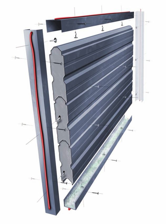
1   Introduction . . . . . . . . . . . . . . . . . . . . . . . . . . 02-05
                                                                                                                       .
  This manual has been developed using
                                                      Overview, Acoustic performance, Fire performance,
  recognised New Zealand standards together
                                                      100% reusable, Minimum waste, Project portfolio,
  with sound engineering principles
                                                      Companies using KOROK®, Industrial and retail
  substantiated through BRANZ laboratory
                                                      applications, Apartments and commercial inter-
  testing and reports.
                                                      tenancy applications, Lift shafts, ducts and stairs,
  This manual in no way supersedes the                Steel buildings and sheds, Client feedback.
  requirements of any Statutory Authority or
  New Zealand Standard but is rather a guide
  to the performance of KOROK® under
                                                  2   Panel Properties. . . . . . . . . . . . . . . . . . . . . . . . 06-07
  certain loading conditions.
  The manual provides builders, engineers,            KOROK® panels, Loading combinations, General
  designers and architects with a user friendly       design notes, References, Standards,
  format for installing and designing                 Manufacturers documents, KOROK® panel
  KOROK® for non load bearing applications.           properties, Vertical span walls, Horizontal span
                                                      walls, Thermal resistance.

  In brief, KOROK® has:
                                                  3   Connections, Span Tables and Graphs . . . . . . . 08-09
    • Fire rated systems ranging from 60
      minutes to 240 minutes.                         Maximum spacings, Shear strength per
    • Acoustic systems ranging from                   fastener, Maximum wall height, Boundary
                                                      members and openings, Installation notes.
      STC 40 to STC 80.
    • Panel dimensions of 250mm high
      by 78mm thick (nominal) in lengths
      up to 9.3 metres.                           4    KOROK® Fire Rated Systems. . . . . . . . . . . .
    • Panels that weigh (nominally)                   10-13
      10.2kg per lineal metre.
                                                      FS1 - 60 minute fi re rated system
    • Panels available in galvanised or
      colour steel.                                   FS2 - 120 minute fi re rated system
                                                      FS3 - 180 minute fi re rated system
                                                      FS4 - 240 minute fi re rated system
  Typical Applications are:
  Q
      ;H;6;@93@64AG@63DKI3>>E8ADE:76E     5   KOROK® Noise Control Systems . . . . . . . . . .14-17
     factories and warehouses.
                                                      NCS1 - STC40 Noise Control System
  Q ;@7?3I3>>E
                                                      NCS2 - STC58 Duct and Shaft Wall System
  Q "@F7D F7@3@5KI3>>E8AD3B3DF?7@FE
     hotels and retirement complexes.                 NCS3 - STC59 Apartment Inter-tenancy Noise Control
  Q %;8FE:38F3@66G5FI3>>E                        System NCS4 - STC76 Theatre Wall Noise Control
  Q 'A;E73DD;7DE                                   System

                                                  6   Installation Information . . . . . . . . . . . . . . . . . .18-28
                                                      General overview, C Track and Angle sections, Cutting
                                                      of KOROK® panels, Horizontal installation, Last panel,
                                                      Corners, Vertical installation, Last panel, Doorways and
                                                      windows, Penetrations, Plumbing and electrical
                                                      services, Shelf loads, Fixing accessories, External wall
                                                      installation.

                                                      Compliance with the New Zealand Building Code
                                                      (NZBC), Quality control, Design guidelines, Limitations,
                                                      Transport, Handling and storage, Strippable fi lm,
       Appraisal No.559 [2018]                        Cleaning, On site handling, Installation, Maintenance,
                                                      Material safety data sheet, Specifi cation, Warranty,
                                                      Disclaimer, Do not substitute any component, Liability,
                                                      Is this publication current?
                                                                                                                         1
www.korok.com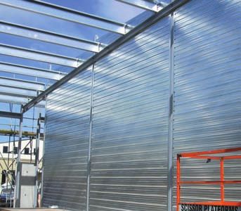
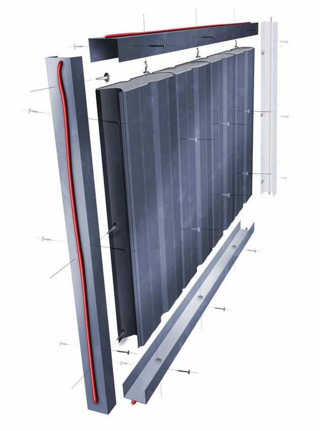
1           Introduction

        Superior fire and acoustic performance with clip-together simplicity

                    BRANZ appraised.
                    Roll formed galvanised steel or colour steel outer shell.
                    Lightweight with aerated concrete core.
                    Fire ratings up to –/240/240.
                    Noise ratings up to STC80.
                    Panels interlock with clip-together simplicity for rapid
                    installation.
                    Can be dismantled and reassembled to accommodate
                    changing requirements.
                    Can be installed horizontally or vertically.

When noise and fi re regulations demand a high performance, no             Fire performance
risk solution, KOROK® will meet the most stringent building code
                                                                                         KOROK® delivers proven two-way fi re resistance
requirements for internal non load bearing walls simply and cost
                                                                                over a long period of time.
effectively.
                                                                          KOROK has been tested and appraised by the Building
                                                                                     ®

Exceptionally strong yet lightweight, the patented interlocking           Research Association of New Zealand (BRANZ).
panels can be easily erected by a small crew, making KOROK®
much faster to install than conventional wall systems.
Construction using KOROK® also allows a building to be made
weather resistant much earlier in the construction cycle allowing
internal work and fi nishing to be started sooner.                         100% reusable, minimum waste
                                                                                         KOROK® is manufactured in New Zealand and
                                                                                         offers unique benefi ts in terms of sustainability and
Acoustic performance
                                                                          environmental performance:
         KOROK'S inherent mass and interlocking design gives              Q 03>>E53@47D7GE764KE;?B>K6;E?3@F>;@9F:7B3@7>E3@6
         it outstanding noise reduction properties making                      reinstalling them in another location.
it highly suitable in buildings where acoustic performance is             Q - :7D3I?3F7D;3>5A?BA@7@FEEF77>3@65A@5D7F73D7
critical, such as cinemas, lecture theatres, apartments, record-               recyclable.
ing studios and industrial/commercial inter-tenancy situations.           Q )3@7>E3D75GEFA??3@G835FGD76FAE;L7?;@;?;E;@9I3EF73F
The unique interlocking design eliminates the risk of sound                    the factory and on the construction site.
“leaks” between panels, and makes installation much faster
and more simple than traditional systems.

2
                                                                                                                         www.korok.com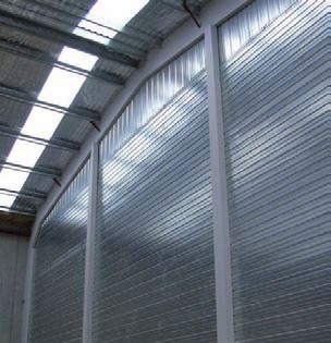
Project portfolio
                Auckland University Business School
                Berkeley Cinemas, Botany Downs
                Farmers Car Park, Christchurch
                Grenada Business Park, Wellington
                Henderson Film Studios, Auckland
                Hoyts Cinemas, Sylvia Park
                Lumina Apartments, Auckland
                NRM Tower, Auckland
                NZ Post Mail Centres (Auckland, Hamilton, Christchurch)
                Precinct Apartments, Auckland
                Scene Three Apartments, Auckland
                Southgate Retail Development, Auckland

                Companies using KOROK®
                Arrow International
                Aspec Construction
                Brookfield Multiplex
                Building Solutions
                Clearwater Construction
                Dominion Constructors
                Ebert Construction
                Fletcher Construction
                Hawkins Construction
                Haydn & Rollett Construction
                Leighs Construction
                Macrennie Construction
                Mainzeal Construction
                Manson Developments
                Naylor Love
                Watts & Hughs Construction

                For more detailed information and case
                studies, go to www.korok.com

                                                                          3
www.korok.com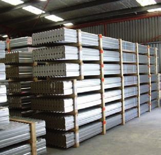
1            Introduction

Industrial and retail applications                                  KOROK® is also an increasingly popular choice for
    In factories, warehouses and bulk retail environments,          factories, workshops and other commercial developments
KOROK® provides strong, solid separation walls that are             where there are multiple tenants and noise is an issue.
secure and fi re compliant with high noise insulating
properties.
In buildings where the interior layout may need to be
reconfigured for future needs, KOROK® is especially
versatile in that it can be easily dismantled and relocated with
no loss of acoustic or fi re performance.
Standard KOROK® has a highly reflective surface and when
left unlined, can help create a brighter, safer working
environment. Alternatively, KOROK® can be supplied in a
range of colour steel paint finishes.

                                                                    Lift shafts, ducts and stairs
                                                                        For lift shafts, duct walls and stair spline walls,
                                                                    KOROK® offers significantadvantagesovert raditional
                                                                    construction.
                                                                    Because it can be installed from one side only, there is no
                                                                    requirement to construct scaffolding inside the shaft, greatly
                                                                    reducing construction time and costs.
                                                                    Unlike traditional systems, KOROK® can be installed before
                                                                    the structure is watertight and also helps prevent water from
                                                                    entering the building through open shafts.

Inter-tenancy applications
         With traditional inter-tenancy wall systems, it is often
         difficult to achieve reliable on-site performance due to
    the complex nature of the system’s installation requirements.
The clip-together simplicity of KOROK® greatly reduces
installation complexity and minimizes the risk of sound
“leaks” or discrepancies in on site acoustic performance.
With a baseline performance of STC59 and a fi re rating of
FRR –/240/120, KOROK® inter-tenancy systems for multi-
unit residential projects exceed all Building Code
requirements for both fi re and noise control.

4
                                                                                                                     www.korok.com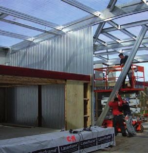
Steel buildings and sheds
      KOROK® is especially efficient and economical when           Client feedback
used for fi re-rated separation and boundary walls in steel
buildings, sheds and similar structures.                          > IGNITE ARCHITECTS:

Installation can generally be managed by a two-man team            Berkeley Cinemas
and no cranes are required on site.                                “KOROK® is far superior to normal construction
                                                                   for a theatre. It took out the possibility of their
Also, the floor slab does not have to be specially engineered
to accommodate the additional weight associated with               being a fl aw by removing a lot of the human error
traditional tilt slab or other similar construction techniques,    factor. It cut out between six and eight weeks worth
leading to significant cost savings.                                of construction time.”
                                                                                               – Jeremy Craig, Architect

                                                                  > FLETCHER CONSTRUCTION:
                                                                    Auckland University Business School
                                                                   “We got two months advantage on the building
                                                                   programme by going to KOROK®. It’s been a test
                                                                   case for Fletcher Building as we look towards
                                                                   introducing KOROK® into our other building
                                                                   projects.”
                                                                                          – Andrew Rolfe, Site Manager

                                                                  > SPANTECH BUILDINGS:
                                                                    Taupo Motorpark
                                                                   “We were looking for a cost-effective alternative to
                                                                   precast panels. KOROK® is much quicker and
                                                                   shortened the project by two to three weeks on an
                                                                   eight week project. It was easy to do and the
                                                                   acoustic rating is brilliant.”
                                                                                                          – Marc Osborne

                                                                  > MAINZEAL CONSTRUCTION:
                                                                    Scene 3 Apartments
                                                                   “The acoustic qualities and fi re qualities were
                                                                   quite a selling point and were well over code
                                                                   requirements. KOROK® construction saved us a
                                                                   lot of time, hassle and risk. The system is so robust
                                                                   and reliable.”
                                                                                      – John Williams, Project Manager
   KOROK® can be manufactured with a colour steel paint finish.

                                                                                                                           5
www.korok.com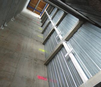
2 Panel Properties
KOROK® panels Standards
KOROK panels are rollformed from zinc coated steel strips.
®
NZS 2589.1:1997
The steel from which the shells are manufactured conforms to Gypsum Linings in residential and light commercial construction.
AS1397:2001.
AS 3566:1988
Steel shells have a base metal thickness of 0.4mm B.M.T. with
Screws – Self Drilling for the Building and Construction Industry
a Z275 zinc coating. These panels have an aerated concrete
core and weigh nominally 10.2kg per lineal metre. NZS 4203:1992
Code of practice for General Structural Design and Design
Loading combinations Loadings for Buildings.
All loading combinations are in accordance with NZ4203:1992
AS/NZS 1170.0:2002
and AS/NZS 1170.0:2002.
Structural design actions. Part 0: General Principles
General design notes NZS 7202
The designs specifi ed in this manual have been carried out in Part 1 Specification for gap filling adhesives.
accordance with NZS4203 and laboratory testing carried out
by BRANZ Limited. Manufacturers documents
The tables and charts are prepared for the use of KOROK in
®
Manufacturers and Suppliers Documents, which refer to work
wall applications i.e. fl oor systems cannot be modelled from in this section are:
the safe load tables in this manual.
Q GF7J ® Insulation Data Sheets
Interpolation of the tables is acceptable. Q " ® Site Guide
Q " ® Fire Rated Systems
References Q )7@7FD3F;A@E3@65>AEGD7E;@ " ® Fire Rated Systems
Q " ® Noise Control Systems
The following references including standards and codes of
Q !;>F; ® New Zealand Technical Manual
practice govern the manufacture of components, use and
design and installation of KOROK® systems. Q );@= ® Batts ® Data Sheets
Q )AI7DE 3EF7@7DE,B75;N53F;A@
7E;9@&3@G3>
Q +A@6A ®,F77>,FG6-D35=E"@EF3>>3F;A@&3@G3>
Q ., ®
DKI3>>,F77>,FG6-D35=,KEF7?
KOROK® Panel
288mm
250mm
78mm
6
www.korok.com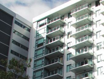
KOROK® panel properties Base                                      KOROK® C Track
Metal Thickness 0.4mm B.M.T. Mass                                 1.15 B.M.T
kg per lineal metre 10.2 nominal Mass
kg/m2 40.8 nominal
EI      60 kNm2B7DB3@7>?;@AD3J;E
EI      387kNm2B7DB3@7>?376975DGE:8AD57B7DG@;F>7@9F:
                                                                  KOROK® Angle
 =' ?.%,=' ?,%,
                                                                  1.15 B.M.T
&3J;?G?:AD;LA@F3>D735F;A@ B3@7>
 ='.%, =',%,

Thermal resistance
                                                                  60mm

R Value 0.43m2 .K/W
./3>G7 0 ? 2 .K
                                                                          60mm

                                                                  Fire Rated Sealant     Grout
     Legend
     .%,/3>G7E:AI@;E8AD.>F;?3F7%;?;F,F3F7>A36;@9
     SLS: Value shown is for Servicability Limit State loading.

                                                                  ;J;@9E

                                                                                                 7
www.korok.com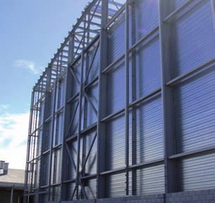
3             Connections, Span Tables and Graphs

Maximum spacings of fasteners for horizontal installation                         Maximum spacings of fasteners for vertical installation

                                           10 x 16 screw fi xings both                                                      10 x 16 screw fi xings both
                                           sides. 1500mm centres max                                                       sides @ 400mm centres.
                                                                                                                           1500mm centres max
                                           C Track fi xings @ 400mm
                                           centres max. Hilti X-EDNI                                                       C Track fi xings @ 400mm
                                           nails to steelwork                                                              centres max. Hilti X-EDNI
                                                                                                                           nails to steelwork
                                           10 x 30 screw fi xings both
                                           sides at each panel joint                                                       10 x 16 screw fi xings both
                                                                                                                           sides of each panel
                                           10 x 16 screw fi xings @
                                           600mm centres both sides                                                        C Track fi xings @ 400mm
                                                                                                                           centres max. M6.5 x 32
                                           C Track fi xings @ 400mm                                                         mushroom head spikes to
                                           centres max. M6.5 x 32                                                          concrete
                                           mushroom head spikes to
                                           concrete

Shear strength per fastener for the following connections
                                                                                                    Design Strength (kN)        Design Strength (kN)
           Connection          Load Direction                             Type
                                                                                                            ULS                         SLS
    Panel to panel             In-plane         10x16 galvanised Steeltite wafer head screws                1.01                        0.83
    Panel sides to C Track     In-plane         10x16 galvanised Steeltite wafer head screws                0.95                        0.78
    Panel ends to C Track      Out-of-plane     10x16 galvanised Steeltite wafer head screws                0.91                        0.74
    Panel sides to C Track     In-plane         10x16 galvanised Steeltite wafer head screws                0.69                        0.22
    Panel ends to C Track      Out-of-plane     10x16 galvanised Steeltite wafer head screws                2.21                        0.77
    C Track to concrete        In-plane         6.5x32 Rawl Mushroom spikes                                 7.84                        2.27
    C Track to concrete        Out-of-plane     6.5x32 Rawl Mushroom spikes                                 7.84                        2.27
    C Track to steel support   In-plane         Hilti® X DN1 16 MX nail                                     4.32                        2.31
    C Track to steel support   Out-of-plane     Hilti® X DN1 16 MX nail                                     4.32                        2.31

NOTE: The design capacities for the fi xings are generally significantly less than
the manufacturers design capacities because of deformation of the fi xing holes.
We have used the lesser of the two values.

8
                                                                                                                                   www.korok.com
Maximum wall height Fig 1. Maximum pressure that can be resisted by horizontal span
9
Use of Tables 8 ULS Design
SLS Design L/150
1. Determine the loads on the KOROK in accordance with
®
7 SLS Design L/200
Differential pressure (kPa)
NZS 4203 1992 or AS/NZS 1170.0 as applicable. 6
SLS Design L/250
SLS Design L/300
2. Use Table 1 and/or Figure 1 to ensure that walls spanning 5
horizontally can carry the loads previously calculated. Use 4
Table 2 and/or Figure 2 to ensure that walls spanning
3
vertically can carry the loads previously calculated.
2
Interpolation of points in the tables is allowed.
1
3. The Tables and Graphs have been generated for a range of
deflection limits i.e. Span/150 Span/200 Span/250 Span/ 300 0
0 1 2 3 4 5 6 7 8
in both the vertical and horizontal panel configurations. Span (m)
4. The walls must be checked for both ultimate limit state
loading (ULS) and serviceability limit state (SLS) loading. Table 1.
SLS SLS SLS SLS
5. Vertical Wall Tables and Graphs have been generated to a Span ULS
Design Design Design Design
(m) Design
maximum of 8m height. L/150 L/200 L/250 L/300
6. Horizontal Wall Tables and Graphs have been generated 2 10.05 9 7.7 6.7
2.5 7.3 6.02 4.94 4.2 3.64
using a 14m high wall. This is the maximum wall height. 3 5.04 3.7 3 2.5 2.17
3.5 3.7 2.42 1.95 1.63 1.39
4 2.82 1.67 1.34 1.1 0.94
4.5 1.94 1.19 0.94 0.78 0.66
5 1.37 0.88 0.69 0.56 0.47
6 0.72 0.51 0.39 0.32 0.26
Boundary members and openings 7 0.38 0.31 0.23 0.19 0.15
The KOROK® walls must be supported on all edges 8 0.17 0.17 0.14 0.11 0.09
and around the perimeter of all openings. The connection
between the walls and the boundary members and the Fig 2. Maximum pressure that can be resisted by vertical span
boundary members themselves must be specifically designed
9
to carry the loads from the KOROK® walls. ULS Design
8
SLS Design L/150
Boundary member loads must not be transferred to the 7 SLS Design L/200
KOROK® panels.
Differential pressure (kPa)
SLS Design L/250
6
SLS Design L/300
The fastener strengths shown in this section may be used 5
to design the connections. Maximum spacing of fasteners is
4
shown on page 8. Refer to Section 6 for installation information.
3
2
Installation note
1
All C Track to Structure, C Track to KOROK® and KOROK® to
0
KOROK® connections shall be in accordance with details 0 1 2 3 4 5 6 7 8
Span (m)
specifi ed in this manual unless specifi ed otherwise by the
Project Engineer.
Table 2.
SLS SLS SLS SLS
Span ULS
Design Design Design Design
(m) Design
L/150 L/200 L/250 L/300
2 10.05 10.05 9.05 7.75 6.77
2.5 7.3 6.05 4.95 4.2 3.64
3 5.04 3.7 3 2.53 2.18
3.5 3.7 2.42 1.96 1.64 1.4
4 2.82 1.68 1.34 1.12 0.95
4.5 2.23 1.21 0.96 0.79 0.67
5 1.79 0.9 0.71 0.58 0.49
6 1.22 0.54 0.42 0.34 0.28
7 0.89 0.34 0.26 0.21 0.17
8 0.66 0.23 0.17 0.14 0.11
9
www.korok.com4 KOROK® Fire Rated Systems
KOROK® fire rated system FS1
78mm wide
System FS1 comprises of 78mm KOROK® panel, with no
linings attached. Standard KOROK® C Track is used
around the perimeter of the wall.
Specification Number FS1
Loadbearing Capability NLB
Fire Resistance Rating – / 240 / 60
Lining Requirements Nil
Sound Transmission Class 40
System Weight Approx 41kg/m2
For installation details refer to section 6.
Due to its unique composition, KOROK® provides exceptional
fire resistance over a long period of time.
However, to achieve the stated fire resistance ratings,
it is critically important to adhere strictly to the design,
installation and construction details in this manual otherwise
the fi re resistance rating may be degraded.
KOROK® fi re rated wall systems have been tested and
appraised by the Building Research Association of New
Zealand (BRANZ). In some cases, a fi re resistance rating has
been based on opinion from the same organisations.
Where specifi c noise control performance is required,
KOROK® can provide a number of proven, acoustic-rated wall
systems (see section 5), or can assist in developing a fully
customised solution.
IMPORTANT: In order to satisfy the requirements of New
Zealand Building Code (clause 4) relating to “structural
stability during fi re”, designers must ensure that KOROK®
elements are supported by primary elements that have at
least the same fi re rating as the KOROK® system that
is used. Exceptionally strong yet lightweight, the interlocking panels can
be easily erected by a small crew, making KOROK® much faster
to install than conventional wall systems.
10
www.korok.comKOROK® fire rated system FS2
78mm wide
System FS2 comprises of 78mm KOROK ® panel, with no
linings attached. Standard KOROK® C Track is used around
the perimeter of the wall with KOROK® Fire Flashing fi xed to
both sides of the top KOROK® C Track.
Specification Number FS2
Loadbearing Capability NLB
Fire Resistance Rating – / 240 / 120
Lining Requirements Nil
Sound Transmission Class 40
System Weight Approx 41kg/m2
For installation details refer to section 6.
Due to its unique composition, KOROK® provides exceptional
fireresistanceoveralongperiodoftime.
However, to achieve the stated fire resistance ratings,
it is critically important to adhere strictly to the design,
installation and construction details in this manual otherwise
the fi re resistance rating may be degraded.
KOROK® fi re rated wall systems have been tested and
appraised by the Building Research Association of New
Zealand (BRANZ). In some cases, a fi re resistance rating has
been based on opinion from the same organisations.
Where specifi c noise control performance is required,
KOROK® can provide a number of proven, acoustic-rated wall
systems (see section 5), or can assist in developing a fully
customised solution.
IMPORTANT: In order to satisfy the requirements of New
Zealand Building Code (clause 4) relating to “structural
stability during fi re”, designers must ensure that KOROK®
elements are supported by primary elements that have at
least the same fi re rating as the KOROK® system that
is used. KOROK® can be installed horizontally or vertically and can be
disassembled, relocated or reconfigured to suit changing space
requirements.
11
www.korok.com4 KOROK® Fire Rated Systems
KOROK® fire rated system FS3
104mm wide
System FS3 comprises of standard 78mm KOROK® panel,
with a layer of 13mm GIB Fyreline® plasterboard each side.
Specification Number FS3
Loadbearing Capability NLB
Fire Resistance Rating – / 240 / 180
Lining Requirements 1 x 13mm GIB Fyreline® each side
Sound Transmission Class 42
System Weight Approx 62.6kg/m2
For installation details refer to section 6.
Lining
1 layer of 13mm GIB Fyreline ® plasterboard each side of the
wall.
13mm GIB Fyreline ® Full height sheets shall be used where possible.
Sheets shall be touch fitted.
Offset joints between sheets by 600mm on opposite sides of
the wall.
All sheet joints must be formed over the outermost face of the
KOROK® panels. Linings are fi xed hard to fl oor.
Due to its unique composition, KOROK® provides exceptional Fastening the lining
fi re resistance over a long period of time.
Fasteners
However, to achieve the stated fire resistance ratings,
25mm x 6g GIB ® Grabber™ Scavenger head Drywall self tap-
it is critically important to adhere strictly to the design, ping screws
installation and construction details in this manual otherwise
the fi re resistance rating may be degraded. Fastener centres
KOROK® fi re rated wall systems have been tested and 300mm centres vertically every 600mm horizontally.
appraised by the Building Research Association of New No fi xing to top and bottom KOROK® C Track.
Zealand (BRANZ). In some cases, a fi re resistance rating has
Adhesive fi xing cannot replace mechanical fasteners in
been based on opinion from the same organisations.
KOROK® Fire Rated Systems.
Where specifi c noise control performance is required,
KOROK® can provide a number of proven, acoustic-rated wall Jointing
systems (see section 5), or can assist in developing a fully All screw heads stopped and all sheet joints tape reinforced
customised solution. and stopped in accordance with the publication entitled “GIB ®
IMPORTANT: In order to satisfy the requirements of New
Site Guide”.
Zealand Building Code (clause 4) relating to “structural
stability during fi re”, designers must ensure that KOROK®
elements are supported by primary elements that have at
least the same fi re rating as the KOROK® system that
is used.
12
www.korok.comKOROK® fire rated system FS4
206mm wide
System FS4 comprises of 2 standard 78mm KOROK® panels
with a 50mm cavity.
Specification Number FS4
Loadbearing Capability NLB
Fire Resistance Rating – / 240 / 240
Lining Requirements Nil
Sound Transmission Class 55
System Weight Approx 82kg/m2
For installation details refer to section 6.
Due to its unique composition, KOROK® provides exceptional
fi re resistance over a long period of time.
However, to achieve the stated fire resistance ratings,
it is critically important to adhere strictly to the design,
installation and construction details in this manual otherwise
the fi re resistance rating may be degraded.
KOROK® fi re rated wall systems have been tested and
appraised by the Building Research Association of New
Zealand (BRANZ). In some cases, a fi re resistance rating has
been based on opinion from the same organisations.
Where specifi c noise control performance is required,
KOROK® can provide a number of proven, acoustic-rated wall
systems (see section 5), or can assist in developing a fully
customised solution.
IMPORTANT: In order to satisfy the requirements of New
Zealand Building Code (clause 4) relating to “structural
stability during fi re”, designers must ensure that KOROK®
elements are supported by primary elements that have at
least the same fi re rating as the KOROK® system that
is used. KOROK® panels are custom manufactured to order in lengths
up to 9.3 metres. This system of manufacture minimises waste
both at the factory and on the construction site.
13
www.korok.com5 KOROK® Noise Control Systems
KOROK® noise control system NCS1
78mm wide
System NCS1 comprises of 78mm KOROK®, with no linings
attached. Standard KOROK® C Track is used around the
perimeter of the wall.
Specification Number NCS1
Loadbearing Capability NLB
Fire Resistance Rating – / 240 / 60
Lining Requirements Nil
Sound Transmission Class 36
System Weight Approx 41kg/m2
For installation details refer to section 6.
KOROK® provides a full range of Noise Control Systems with
STC ratings from STC 40 to STC 80.
All KOROK® Noise Control Systems have a minimum Fire
Resistance Rating (FRR) of – /240/ 60.
The Noise Control Systems detailed in this manual cover
common situations where sound control is required. Where a
specifi c performance is required (e.g. duct walls), KOROK® will
assist you to develop a customised noise control system.
KOROK® Noise Control Systems have been tested at the
Acoustic Testing Service, University of Auckland, The Acoustic
Laboratory, Royal Melbourne Institute of Technology or have
been derived from tested systems and based on acoustical
opinion.
Spantech Buildings found KOROK® to be a cost effective
alternative to pre-cast concrete panels for the inter-tenancy
walls in their Taupo Motorpark development.
14
www.korok.comKOROK® noise control system NCS2
(duct & shaft walls) 175 mm wide
System NCS2 comprises a standard 78mm KOROK® panel,
20mm cavity, 64mm steel stud, R1.8 (75mm) Pink® Fibreglass
Batts® and a layer of 13mm GIB Noiseline® .
78mm KOROK®
Specification Number NCS2
R1.8 (75mm) Pink® Loadbearing Capability NLB
Fibreglass Batts® Fire Resistance Rating – / 240 / 120
Lining Requirements 1 x 13mm GIB Noiseline®
64mm steel stud
Sound Transmission Class 58
13mm GIB Noiseline ®
Rw (C;Ctr) 57 (-2 ; -8) dB
System Weight Approx 59kg/m2
20mm cavity
For installation details refer to section 6.
Framing Fastening the lining
Steel stud dimensions to be 64 x 34 x 0.55mm nominal with Fasteners
6mm return. 25mm x 6g GIB ® Grabber™ Scavenger Head Drywall Self
Steel channel dimensions to be 64 x 30 x 0.55mm nominal. Tapping screws.
Channel runners are fi xed to the floor and ceiling in true Fastener centres
alignment. 300mm centres up each stud.
Stud spacing at 600mm centres maximum. Place studs to No fasteners to top and bottom channel sections.
allow a 15mm expansion gap at the top of the frame.
Place fasteners no closer than 12mm to the sheet edge.
The studs are held in place by the “grip” of the channel
runners. No other fi xing is to be used.
Acoustic sealant
A bead of KOROK® Fire Rated Joint Filler ® is required
Sound control infill
around the perimeter of the lining.
R1.8 (75mm) Pink ® fibreglass Batts ® installed between the
studs on the inside of the steel frame.
Jointing
All fastener heads stopped and all sheet joints tape
Lining
reinforced and stopped in accordance with the publication
1 layer of 13mm GIB Noiseline ® fi xed vertically to framing.
entitled “GIB ® Site Guide”.
Full height sheets shall be used where possible. Where sheet
end butt joints are unavoidable, they must be formed over nogs
with the same cross sectional dimensions as the studs.
Sheet joints are touch fi tted. Sheet joints must occur on
framing. The lining on both sides of the frame shall be fi xed
hard to the floor.
15
www.korok.com5 KOROK® Noise Control Systems
KOROK® noise control system NCS3
(apartment inter-tenancy) 188mm wide
System NCS3 comprises a standard 78mm KOROK® panel,
20mm cavity, 64mm steel stud, R1.8 (75mm) Pink® Fibreglass
78mm Batts® and a layer of 13mm GIB Noiseline® on one side, with a
KOROK® layer of 13mm GIB® Standard plasterboard on the other side.
R1.8 (75mm)
Pink ® Fibreglass Specification Number NCS3
Batts ® Loadbearing Capability NLB
64mm steel stud Fire Resistance Rating – / 240 / 120
Lining Requirements 1 x 13mm GIB Noiseline®
13mm GIB ®
Standard 1 x 13mm GIB® Standard
plasterboard
plasterboard
13mm GIB Noiseline ® Sound Transmission Class 59
20mm cavity
Rw (C;Ctr) 58 (-2 ; -8) dB
System Weight Approx 68kg/m2
For installation details refer to section 6.
Fastener centres
300mm centres up each stud.
Framing
No fasteners to top and bottom channel sections.
Steel stud dimensions to be 64 x 34 x 0.55mm nominal with
Place fasteners no closer than 12mm to the sheet edge.
6mm return.
Steel channel dimensions to be 64 x 30 x 0.55mm nominal.
Channel runners are fi xed to the floor and ceiling in true
Acoustic sealant
alignment. A bead of fire resistant sealant is required around the
Stud spacing at 600mm centres maximum. Place studs to allow perimeter of the lining.
a 15mm expansion gap at the top of the frame. The studs are
held in place by the “grip” of the channel runners. No other Jointing
fi xing is to be used. All fastener heads stopped and all sheet joints tape
reinforced and stopped in accordance with the publication
Sound control infill entitled “GIB ® Site Guide”.
R1.8 (75mm) Pink ® fibreglass Batts ® installed between the R
studs on the inside of the steel frame. Frequency One-third
f octave
Hz dB
Lining 50 18.8
Side 1: 1 layer of 13mm GIB ® Standard Plasterboard. 63 25.5
80 27.6
Side 2: 1 layer of 13mm GIB Noiseline ® fi xed vertically to framing. 100 34.2
125 36.8
Full height sheets shall be used where possible. Where sheet end 160 41.1
200 44.3
butt joints are unavoidable, they must be formed over nogs with 250 47.8
the same cross sectional dimensions as the studs. 315 51
400 54
Sheet joints are touch fi tted. Sheet joints must occur on framing. 500 57.5
630 60.5
The lining on both sides of the frame shall be fi xed hard to the 800 63.4
floor. 1000 66.1
1250 69.2
1600 71.1
Fastening the lining 2000 70.2
2500 68.3
Fasteners 3150 69.2
4000 73.7
25mm x 6g GIB ® Grabber™ Scavenger Head Drywall Self 5000 76.8
Tapping screws. Note: Bold values are used to calculate STC and Rw
16
www.korok.comKOROK® noise control system NCS4
(theatre wall) 600mm wide
System NCS4 comprises a 600kg/m3 KOROK® panel with a
layer of 90mm x 42kg/m3 insulation attached to one face. There
78mm KOROK®
is a 444mm air gap then a second 600kg/m3 KOROK® panel.
600kg/m 3
90mm 42kg/m 3
Specification Number NCS4
insulation
Loadbearing Capability NLB
78mm KOROK®
Fire Resistance Rating – / 240 / 240
600kg/m 3
Lining Requirements Nil
Sound Transmission Class 76
Rw (C;Ctr) 75 (-2; -9) dB
System Weight Approx 135.8kg/m2
For installation details refer to section 6.
This is one example of a high performance KOROK®
Sound Rw
Noise control system typically used in movie theatres, Centre
Transmission Loss : Reference Curve
lecture theatres, film studios etc. Generally, KOROK® will Frequency Hz
R dB dB
work together with the project acoustic consultant to 50 30 -
develop a customised solution depending on the specifi c 63 30 -
needs of the project. 80 46 -
100 48 -
A variety of configurations are available depending on the 125 55 60
160 58 63
construction of the building, the level of noise reduction 200 65 66
required and the overall width of the wall design. 250 68 69
315 71 72
400 71 75
500 73 76
630 73 77
800 77 78
1000 82 79
1250 86 80
1600 86 80
2000 88 80
2500 92 80
3150 92 80
4000 91 80
5000 90 -
KOROK® was used for the acoustic rated walls of New Zealand’s
largest film studio and sound stage at Henderson in Auckland.
17
www.korok.com6 Installation Information: General Overview
Horizontal Installation
C Tracks or Angle sections
are fi xed to structural
elements (steelwork) at
400mm centres with Hilti
X-EDNI nails
When fi xing C-track or
Angle sections to concrete,
use M6.6 x 32 mushroom
head spikes at 400mm
centres
Panels are fi xed together
with 10 x 16 screws on both
sides at 1500mm centres
A 25mm – 30mm bed of
grout is poured into the
bottom C-track just prior to
installing the first panel
The C-track or Angle section must
have a 15mm bead of fire resistant
sealant between the track and the
structure it is being fi xed to
Corner joints should be
sealed with fire resistant sealant
18
www.korok.comVertical Installation
C-tracks or Angle sections
are fi xed to structural elements
(steelwork) at 400mm centres
with Hilti X-EDNI nails
When fi xing C-track or
Angle sections to concrete,
use M6.6 x 32 mushroom head
spikes at 400mm centres
The C-track or Angle section
must have a 15mm bead
of fire resistant sealant
between the track and the
structure it is being fi xed to
Panels are fi xed together with
10 x 16 screws on both sides at
1500mm centres
Corner joints should be
sealed with fire resistant sealant
19
www.korok.com6 Installation Information
Depending on requirements, KOROK® can be installed Horizontal Wall, bottom
horizontally or vertically. The fi rst step is to fi x C Track around
the perimeter of the wall. In some situations, Angle sections
are used instead of C Track for ease of installation.
C Track sections come in a standard profile with a 60mm
nominal flange. When C Track is fixed to a concrete floor, it
must be isolated from the slab by using fire rated sealant, to
smooth out any irregularities in the surface of the concrete.
C Track and Angle sections are normally 3600mm long and
should be fixed at not more than 400mm centres (unless
specifically designed).
Fixings should be placed within 100mm from the end and
should be specifically designed for loadings.
For fire and acoustic rated walls, the C Track or Angle section
must have a bead of fi re resistant sealant between it and the
structure it is being fixed to.
Horizontal Wall, top, C Track
Cutting of KOROK® panels
KOROK® panels can be cut to length with the use of a Sabre
saw or Evacuated grinder to minimise dust.
Where KOROK® panels are trimmed to width, the cut section
of the panel is fitted with C Track and is always the last panel
abutting the wall, column or soffit. The panel is t hen sealed
and fixed in position.
C Track
Horizontal Wall, top, using angle sections
Angle
20
www.korok.comVertical Wall, bottom, C Track Vertical Wall, bottom, using angle sections
Vertical Wall, top, C Track Vertical Wall, top, using angle sections
Vertical Wall with fire flashing, top Horizontal Wall with fire flashing, top
For system FS2, a fire flashing is required at the top on both sides of the wall
21
www.korok.com6 Installation Information
Horizontal installation Figure 1
Horizontal Installation of the KOROK panels requires C Track to
®
be fi xed to structural walls, columns, portals etc.
To ensure tightness of fixture, a 15mm bead of fire resistant
sealant is run around the perimeter before the C Track or Angle
sections are laid and fixed.
Grout is poured into the fl oor C Track just prior to the installation
of the KOROK® panels. This forms a bearing surface for the
female end of the panel and is also a fi re and acoustic rated seal.
The cementitious grout should be non shrink high performance
(Hilti® CM651-48). Fill the C Track to a depth of 25-30mm. Any
overflow when the panel is placed in the C Track must be wiped
off immediately (Figure 2).
Ensure that the first panel is level after fitting into the C Track
and grout. Screw fix panel to C Track (Figures 2 & 3).
Subsequent panels are placed in a tilt and snap action (Figure 4).
Last panel Figure 2
To get the last horizontal panel in, the C Track is cut on one
side approximately 400mm from the top of the wall (Figure 5).
The tab is folded back to allow entry of the last panel.
Fire resistant sealant is applied. The angle is then fixed to
the soffit and panel (Figures 6 & 7).
Corners
Where internal or external corners are required, panels
should be finished by fixing C Track to the vertical face.
C Track should also be fixed to the side of the finished wall
channel. Fire resistant sealant must be used between the
C Tracks. Fixing between C Tracks should be at 300mm
centres (Figure 8).
Figure 3
22
www.korok.comFigure 7
Figure 4
Figure 5 Figure 8
Figure 6 Figure 9
15mm sealant bead
between C Track/Angles
and supporting platform
Grout filled base
20mm deflection head
23
www.korok.com6 Installation Information
Vertical installation Figure 1
Vertical installation of the KOROK panels requires
®
C Track to be fixed to walls, columns and soffits etc.
To ensure tightness of fixture, a 15mm bead of fire resistant
sealant is run around the perimeter before the C Tracks or
Angle sections are laid and fixed (Figure 1).
The first panel is placed inside the C Track (slightly tilting
back) and is slid into the vertical position (Figure 2). The first
panel is levelled and then fixed into position. Panels push into
place respectively until the wall is nearly completed (Figure 3).
Last panel
Stop short of the end vertical KOROK® C Track by
approximately 1 metre and cut out a 600mm angle section from
the top and bottom C Track. Plan ahead and make an
allowance for a 50mm overlap onto the panels installed prior to
the last remaining two panels (Figures 4 & 5).
Figure 2
Make your end cut ensuring that a distance of 500mm
remains for the last two panels to be squeezed into position
(Figure 6). Once in postion, simply replace the angle and fix to
panels. Screw the C Track and Angle sections to the panels in
the normal fashion.
Figure 3
24
www.korok.comFigure 4 Figure 7
15mm sealant bead
between C Track/Angles
and supporting platform
Figure 5
Figure 6
25
www.korok.com6 Installation Information
Doorways and windows Figure 1
C Track is cut to the trim size for doors, windows and large
penetrations. As the wall is assembled the C Track is fitted and
sealed and fixed as per the standard details (Figure 1).
An engineer must ensure that wind face load and panel self
weight loads can be transferred at wall openings.
Penetrations
Where penetrations into KOROK® are required, the use of a
grinder, Sabre saw or hole saw to remove the steel shell is
ideal. The aerated concrete is easily removed.
Any gaps in, or services that penetrate through fire rated
construction are to be fire rated using certified proprietary
systems such as fire collars, fire wraps, intumescent systems
etc. The systems are to be installed as required by the
certifi cation and manufacturer of the product.
KOROK® should be earthed where electrical equipment or
unsheathed cables may come into contact with the metal work.
Plumbing and electrical services
Copper and brass piping should be isolated from direct
contact with the steel shell. Similar care should be taken
when contact with dissimilar metals is possible.
Shelf loads
KOROK® can be used to carry shelf loads. The capacity of
KOROK® to carry shelf loading is dependant upon variables
such as shelf design, shelf fastening methods, wall height and
shelf location.
Fixing accessories
Where practical, services and accessories should be fi xed
through the male / female shell connections, where the steel
shell has greatest thickness (1.2mm B.M.T.).
Where loads are higher e.g. 50 x 50 timber framing for an
internal gutter, fixings should extend through the panel.
External wall installation
KOROK® is designed for internal non loadbearing walls. For
external walls, we recommend that KOROK ® should be clad
with an external weather proof system e.g. a profile metal
cladding. KOROK® (NZ) Ltd can provide site specifi c details.
26
www.korok.comNew Zealand Building Code (NZBC) compliance Store KOROK® panels on site fl at or in their pallets.
Under normal conditions of dry internal use, KOROK® systems Storage should provide a firm dry base, protected from the
have a serviceable life in excess of 50 years and satisfy the weather, accidental damage and moisture.
requirements of NZBC Clause B2 – Durability. The panels should be stored on bearers not more than 2000mm
KOROK® Fire Rated Systems can be used to provide passive fi apart.
re protection in accordance with the requirements of NZBC Stack heights are limited to 10 pallets.
Clause C3 – Spread of Fire.
The KOROK® panels must be stored under clean, dry and
In order to satisfy the requirements of NZBC Clause C4 – ventilated conditions.
Structural Stability during Fire, designers must ensure that
Adequate cover should be provided and water must not be
fire rated elements are supported by elements having at least
allowed to lie on the panel surfaces, which will cause staining
the same Fire Resistance Rating (FRR). Collapse of elements
and degradation of the surface coatings.
having a lesser FRR shall not cause the consequential collapse
of elements required to have a higher FRR. If bundles become wet the panels should without delay be
separated, wiped with a clean cloth and stacked so that the
Quality control circulation of air will complete the drying process.
The performance ratings of the published systems have been
obtained by independent testing and opinions sourced from Strippable fi lm
organisations with accredited quality assurance. It is of prime KOROK® panels will generally be coated with a plastic
importance to pay strict attention to the details of design, film to provide protection during handling and transportation.
construction and workmanship, otherwise the performance This film has a very short life when exposed to exterior
could be significantly degraded. conditions and must be removed immediately after installation.
It must not be left lying in the sun or at the site for more than
Design guidelines a few hours. Failure to remove the film will lead to difficulties
The recommended maximum span for KOROK® Fire Rated later with its removal.
Systems is 4000mm. Greater spans are subject to specifi c
engineering design. Cleaning
At the completion of the job and at the finish of each days work,
Limitations it is essential that the completed area be thoroughly cleaned of
Adhesive fi xing cannot replace mechanical fasteners in all swarf, rivet stems, nails, drillings and screws, etc, normally
KOROK® Fire Rated Systems. associated with the installation of metal panels.
Do not install KOROK® above the span and height limits stated Hot swarf should not be allowed to contact pre-painted sheet
in this booklet. material. Any grinding, welding or drilling carried out above
the wall level should be done with the panels appropriately
Transport, handling, and storage covered to avoid swarf contact.
Generally, lengths of KOROK® are delivered to site by Failure to do so will result in unsightly staining of the surface
long trailers and articulated trucks and access to and on as the metal particles rust or oxidise.
building sites must be adequate to accommodate these types
of vehicles. On site handling
Off loading and site storage or craneage onto site is the Handle units carefully prior to their installation. Avoid knocks,
responsibility of the client and suitable arrangements should bumps and scratches, which may lead to maintenance issues
be made prior to delivery. later. Keep KOROK® dry prior to installation.
KOROK® products are packed and protected against damage
Installation
during delivery but care must be exercised during unloading.
Specifi c design advice should be sought where KOROK® is to
Lengths must be adequately supported during unloading and be subject to point loads or other distributed loading other than
where packs are broken and panels lifted by hand, care must wind.
be taken not to slide or drag the panel and scrape the finished
Ensure connection between KOROK® panels are properly
surfaces of the product.
made.
Where it is necessary for KOROK® Panels to be stored on site
they should be placed away from the building operations, if Ensure connections of KOROK® panels to the structure are
possible, in the order in which they will be fixed. adequate.
27
www.korok.com6 Installation Information
Maintenance Do not substitute any component
All cladding products are subject to the cumulative effects of KOROK® fi re and noise rated systems are not generic.
weather, dust and other deposits. Maintenance regimes are to Where specifi ed in this manual, branded components must
be in accordance with maintenance recommendations for New be used when specifying and installing KOROK® systems.
Zealand Steel Products used for roofing and wall cladding. Substituting any component of any system shown in this
manual may compromise the performance of the system.
Material Safety Data Sheet
A Material Safety Data Sheet (MSDS) is available on Liability
request from KOROK® Building Systems NZ Ltd or from our KOROK® New Zealand accepts no liability if any KOROK®
website: www.korok.com Fire Rated System or Noise Rated System is not designed
and installed in strict accordance with instructions contained
Specifi cation in this publication.
KOROK® have prepared a technical specifi cation suitable for
inclusion in contract documents by Architects, Engineers or Is this publication current?
Builders. This may be freely copied (in full) or reproduced (in This publication may be superseded by a new publication.
full) and is available by contacting KOROK® Building KOROK® Building Systems NZ Ltd accepts no liability for
Systems NZ Ltd or from our website: www.korok.com reliance upon publications that have been superseded.
If you are unsure whether this is the current publication,
Warranty please call 07 849 7062 to check.
KOROK® Building Systems NZ Ltd supplies the KOROK®
wall system and warrants it to be free from defects in material
and workmanship. KOROK® Building Systems NZ Ltd will at
its own option replace and/or repair any product found to be
defective, provided it has been stored, installed and maintained
strictly in accordance with the requirements and
recommendations of KOROK® technical literature. This
warranty is in addition to any statutory rights to the customer.
KOROK® Building Systems NZ Ltd cannot be held
responsible for deterioration to galvanised products caused by
poor handling or storage practices after the product has arrived
at the customers site.
All KOROK® building products are designed to satisfy New
Zealand conditions.
Disclaimer
KOROK® Building Systems NZ Ltd reserves the right, at any
time, at its own discretion and without notice, to discontinue or
change the features, designs, materials, colours and other
specifi cations of its products and to either permanently or
temporarily withdraw any such products from sale without
incurring any liability.
This booklet is published as a general guide only and must not
be used in preference to detailed technical advice from an
appropriately qualifi ed person where application differs from
those described herein.
To the best of KOROK Building Systems NZ Ltd knowledge,
all information is correct at the time of printing.
Whilst every effort has been made to ensure the material
contained within this document is accurate and correct,
no responsibility or liability, in part or whole by the authors,
editors or publishers of this manual will be accepted for misuse, KOROK® can provide an effective sound barrier in any situation
misreading or deviation from the recommended installation where noise is a problem.
details.
28
www.korok.comStamp of approval from the Post Office Blockbuster hit at the Movies
Because it’s so quick and easy to install, KOROK® With noise ratings up to STC 80 plus, and fire ratings
helped New Zealand Post meet tight deadlines up to –/240/240, KOROK® played a leading role in the
when building their mail sorting centres in construction of Hoyts Cinemas in Sylvia Park and
Auckland, Hamilton and Christchurch. Berkeley Cinemas in Botany Downs.
Top performer at Taupo Motorpark Honoured at Auckland University
Spantech Buildings chose KOROK® for the After carefully studying all the options, Fletcher
inter-tenancy walls of their Taupo Motorpark development Construction chose KOROK® for the Auckland Business
because it was faster than any other option. School lecture theatres, lift shafts and stairwells.
The fastest way to the top floor The key to apartment privacy at Scene 3
KOROK® is easily the simplest way to build lift Because their inter-tenancy walls are made of
shafts, ducts and stair spline walls in any project KOROK®, Scene 3 apartment owners never lose a
where speed of construction really counts. night’s sleep over the goings on next door.KOROK
22 Norris Ave PO Box
20182 Te Rapa, Hamilton
0800 773 777
www.korok.comYou can also read