Installation Guide For DC Electric Thruster Models SE250, SE300 - EN - Sleipner
←
→
Page content transcription
If your browser does not render page correctly, please read the page content below

Installation Guide
                        For DC Electric Thruster Models
                        SE250, SE300

SLEIPNER AS                                       DOCUMENT ID: 5244
P.O. Box 519                                         REVISION: 12
                                                                       IM

N-1612 Fredrikstad                                        DATE: 2021
Norway
www.sleipnergroup.com                               LANGUAGE: EN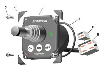
EN                                                                                     Contents
Bow Installation Instructions                                                                             Products
Bow Installation Considerations and Precautions..................... 3
Thruster Measurements ............................................................ 4                      SE300/300TC - SE300 Tunnel thruster, 48V
Thruster Specifications............................................................... 5                  SE250/300TC - SE250 Tunnel thruster, 24V
Technical Specifications ............................................................ 5
Positioning of the tunnel / thruster............................................. 6
Tunnel Length.............................................................................. 7
Tunnel installation in sail boats................................................... 8
Water Deflection.......................................................................... 9
Tunnel ends.............................................................................. 10
Tunnel installation............................................................. 11 - 12
Stern tunnel installation........................................................... 13

Thruster Installation Instructions
Thruster Installation Considerations and Precautions............ 14
Gear Leg & Motor Bracket Installation..................................... 15
Propeller Installation................................................................ 16
Motor Installation..................................................................... 17
Thruster Electrical Installation................................................ 18
Electrical Specifications .......................................................... 19
Control Panel Cable Installation ............................................. 20
Visual Wiring Diagram .............................................................. 21
Technical Wiring Diagram ................................................. 22 - 24
Control Panel Installation ........................................................ 25

Pre-delivery Checklist..................................................... 26

Service and Support ....................................................... 27
Product Spare Parts and Additional Resources ................ 27
Warranty statement ....................................................... 27

       DECLARATION OF CONFORMITY                                                                MC_0020

                        Sleipner Motor AS
                        P.O. Box 519, Arne Svendsensgt. 6-8
                        N-1612 Fredrikstad, Norway

                        Declare that this product with accompanying standard control systems complies with the
                        essential health and safety requirements according to:

                        DIRECTIVE 2013/53/EU
                        DIRECTIVE 2014/30/EU
                        DIRECTIVE 2014/35/EU

      2                                                                              SE250 & SE300                    5244      - 12            2021
It is the installers responsibility
When installing Sleipner equipment follow the outlined regulations/ classification rules (electrical/ mechanical) according to
international or special national regulations. Instructions in this guide cannot be guaranteed to comply with global electric/
mechanic regulations/ classification rules.
Follow all health and safety laws in accordance with their local outlined regulations/ classification rules.
Before installation, it is important that the installer reads this guide to ensure necessary acquaintance with the product.
The recommendations made in this manual are guidelines ONLY, and Sleipner Motor AS (Sleipner) strongly recommend that before
installation, advice is obtained from a naval architect familiar with the particular vessel and regulations/ classifications.
This manual is intended to support educated/ experienced staff and is therefore not sufficient in all details for professional
installation. (NB: These instructions are only general instruction. If you are not skilled to do this work, please contact professional
installers for assistance.)
All electrical work must be done by a licensed professional.
Faulty installation of Sleipner products will render all warranty given by Sleipner Motor AS void. MC_0038
EN Bow Installation Considerations and Precautions MC_0031
• The thruster must NOT be installed in compartments that require ignition proof electric equipment. If necessary, make a separate compartment.
(NB: Ignition Protected systems are tested to be installed in areas with possible explosive gases in accordance with ISO 8846)
• The electro motor will generate some carbon dust so any storage compartments must be separated from the thruster to prevent nearby items
becoming dusty/ dirty. (NB: IP version motors generate dust but are enclosed.)
• When installing the thruster electro motor in small compartments, ensure the compartment is well ventilated to allow for cooling of the electro
motor.
• If the height of the room you are installing the thruster is limited, the thruster can be installed horizontally or at any angle in-between.
- If the electro motor is positioned more than 30 degrees off vertical, it must be supported separately.
- Beware of keeping installation within advised measurements. No part of the propeller or gear house must be outside the tunnel.
• Do not install the thruster in a position where you need to cut a stiffener/ stringer/ support that may jeopardise the hull integrity without checking
with the boat builder this can be done safely.
• The electro motor, components and cables must be mounted so they remain dry at all times.
• We advise painting the gear house and propellers with anti-fouling. (NB: Do not paint the anodes, sealing, rubber fittings or propeller shafts)
• Do not finish the inside of the tunnel with a layer of gel-coat/ topcoat or similar. There is only room for a thin coat of primer and two layers of anti-
fouling between the tunnel and the props.
• Don’t install the electro motor close to easily flammable objects or equipment as it will reach over 100°C before the temperature switch is activated.
• Do not store items close to the thruster motor. Any loose items near the thruster motor is a potential fire hazard and can cause undesired short-
circuiting.
EN Thruster Installation Considerations and Precautions MC_0257
Before installation, it is important that the installer reads this guide to ensure necessary acquaintance with this product.
• The electro motor must be handled with care. Do not lift it by internal cable connections, main terminals or placed down on the drive shaft.
• The thruster power supply circuit must include the recommended sized fuse and a battery isolation switch.
• Never run the thruster out of water.
• It is important to follow the guidelines in this manual. Failure can result in severe damage to the thruster.
SE250 & SE300 5244 - 12 2021 3L W
H
WD
ID
Propeller position will vary
with each thruster model
T
TL
Twin Propeller
The gear leg/ propeller(s) must
never extend out of the tunnel
Tunnel centre line
MG_0075
EN Thruster Measurements MC_0126
Measurement *250 *300
Measurement description 24v 48v
code mm inch mm inch
ID Internal tunnel diameter 300 11,81 300 11,81
H Motor Height 490 19,29 457 17,99
W Width 337 13,27 350 13,78
L Length 274 10,79 274 10,79
WD Water Depth 300 11,81 300 11,81
TL Minimum tunnel length 273 10,75 273 10,75
TL (recommended) Recommended tunnel length 333 13,11 333 13,11
T (min) Minimum tunnel wall thickness 10 0,39 10 0,39
T (max) Maximum tunnel wall thickness 12 0,47 12 0,47
*Valid for SE & SEP
4 SE250 & SE300 5244 - 12 2021EN Thruster Specifications MC_0140
Description * 250 * 300
Available DC System (v) 24v 24v & 48v
Thrust 12v or 24v (kg * lbs) 300 kg * 661 lbs 350 kg * 749 lbs
Thrust 10.5v or 21v (kg * lbs) 250 kg * 551 lbs 300 kg * 661 lbs
Typical Boat Size (m * ft) 18m - 25m * 60ft - 84ft 22m - 30m * 72ft - 100ft
Propulsion System Twin Counter Rotating Twin Counter Rotating
Power (kw * Hp) 11.4kw * 15.5hp 15kw * 20hp
Weight (kg * lbs) 70kg * 154lbs 73kg * 160lbs
*Valid for SE / SE IP & SEP / SEP IP
EN Technical Specifications MC_0052
Motor: Custom made reversible DC-motor.
Gear house: Seawater resistant bronze. Ball-bearing at propeller shaft and a combination of ball bearing and slide bearing at drive shaft.
(Pre-filled and sealed for life)
Motor bracket: Seawater resistant aluminium, galvanically insulated from the motor..
Tunnel: Cross spun with rowing G.R.P tunnel
Steel & aluminium tunnels available at request.
Propeller: 5-blade skewback “Q-prop” propeller, fibreglass reinforced composite.
Batteries: Minimum recommended battery capacity (cold crank capacity by DIN/SAE standard)
Contact a battery supplier for more information.
Max. use: 2 - 3 min. duty cycle at 20°C
Safety features: - Electronic time-lapse device protects against sudden change of drive direction.
- The electric thermal cut-off switch in electro motor protects against overheating (auto-reset when electro motor cools down).
- Flexible coupling between electro-motor and drive shaft protects electro motor and gear system if propeller jams.
- Original Sleipner panels shut off automatically 6 minutes after last use. This interval can be adjusted in 5 min steps up to 60
minutes or turned off completely.
- Original Sleipner panels use child-safe double ON buttons.
- An integrated microprocessor monitors solenoids, reduce wear and risk of solenoid lock-in.
- Auto-stop of the thruster occurs when an undesirable solenoid lock-in occurs or when continuous operation cut-off timer
exceeds 3 minutes.
SE250 & SE300 5244 - 12 2021 51
Pivot
A
point
B
important
Lowered rotation power performance
Stronger rotation power performance
2 Water line
WD
Ø
min 1/4Ø
(Recommended)
min 1/4Ø
(Recommended)
MG_0001
EN Positioning of the tunnel / thruster MC_0003
Aim to install the thruster as far forward as possible (1)
Due to the leverage effect around the boats’ pivot point. The distance difference from the boat pivots’ point to the thruster will determine the amount
of real rotation power for the boat.
Aim to install the thruster as deep as possible under the waterline (2)
Deeper installations prevent air from being sucked into the tunnel from the surface, resulting in reduced thrust performance and increase noise levels
during operation. Deeper installations increase water pressure for maximum efficiency from the thruster.
The centre of the tunnel should be a minimum of 1 x the tunnel diameter below the waterline. The installer must make evaluations based on thruster
performance, boat type and operating conditions. As a general recommendation, the position of the tunnel should not be a minimum of 1/4 of the
diameter of the tunnel from the boat keel. (NB: This can be overlooked depending on the installation methods defined in this manual.)
6 SE250 & SE300 5244 - 12 20211
3
Do not allow the variable length of the tunnel walls to vary in length
excessively.
EG. the top tunnel wall is x 4 longer than the bottom wall. Water flow must have
space to "straighten"
itself for best
2 Cavitation performance.
4 STANDARD USE 5 FLAT BOTTOM HULL 6 HIGH-SPEED OPERATION
Water
Forces
Increase tunnel length to
The gear leg/ propeller(s) must prevent a circular water vacuum Increase tunnel length to protect
never extend out of the tunnel cavity between the propeller and the propeller from water forces
the hull of the boat. when high-speed cruising. MG_0048
EN Tunnel Length MC_0003
Optimal tunnel length
Achieving the correct tunnel length depends on many factors from the hull type, operation and environmental conditions.
Tunnels should avoid being longer than 4 x the tunnel diameter as this will reduce thruster performance. (NB: Installing long length tunnels can flex/
bend over time and may require additional support. Consult with a naval architect.)
1. Do not allow the variable length of the tunnel walls to vary in length excessively.
EG. the top tunnel wall is x 4 longer than the bottom wall.
2. If the tunnel is too long, the friction inside will reduce the water speed and thereby the thrust.
3. If the tunnel is too short (typically only in the bottom section of the tunnel) cavitation problems can occur as water flow will not be able to
“straighten” itself before reaching the propeller. This cavitation will reduce performance and increase noise during operation.
Thruster within the tunnel
It is important the propellers and the lower unit/ gear leg must be entirely inside the thruster tunnel. Propellers that protrude from the tunnel will not
perform as intended.
4. Standard Use
Tunnel length must be long enough to ensure the propellers are not extruding the tunnel.
5. Flat Bottom Hull
Tunnel lengths must be longer than the standard measurement outlined within the manual to ensure a circular vacuum is not created between the
thruster and the bottom of the boat.
6. High-Speed Boats
Tunnel lengths must be increased to protect the propeller from damage when crashing against the water surface during high-speed cruising. (NB:
This can include the length of a spoiler)
SE250 & SE300 5244 - 12 2021 7
1
Min
Pos. A Pos. B
MG_0004
EN Tunnel installation in sailboats MC_0003
Some sail boats have a flat bottom and shallow draft in the bow section. This can make installing the thruster as far forward from the boats main pivot
point difficult. (Fig. 1).
However, it is possible to install a tunnel thruster in most sail boats, even when the hull does not directly support the fitting of a tunnel.
Instead fit the tunnel halfway into the underneath section of the existing hull. Strengthen it with a deflector/ spoiler directing the water flow around
the tunnel. This will allow installation of the thruster in the proper position on the boat, maintaining the reliability and space advantages of the tunnel
thruster.
This installation is being used by some of the world’s largest sail boat builders and has proven to give little to no speed loss during normal cruising.
This can also be an installation method for flat bottomed barges to avoid extremely long tunnels and large oval tunnel openings in the hull.
8 SE250 & SE300 5244 - 12 20211 2 3
4
High water force
while underway
High water force
while underway
from wave contact
MG_0003
EN Water Deflection MC_0003
1. A possible problem in sail boats or fast powerboats is that a non-rounded surface can generate drag from the back face of the tunnel, as it creates
a
“flat” area facing the flow of water (1).
This problem can be solved in two different ways, depending on what is possible or easier to perform.
2. The best solution which generally reduces the most drag is to make a recess in the hull at the back of the tunnel. As the back face is removed
water can flow freely past the tunnel entry. The depth and shape of this recess will depend on the boat and the angle facing up/ down aft of the
tunnel insert. Normally it is angled slightly down because of the water flow on this area (2).
3. Making a deflector/ spoiler in front and underneath the tunnel can also reduce damage to the thruster and drag. The deflector/ spoiler will push
the water flow out from the hull so water can pass by the back face of the tunnel. The shape and size of this deflector/ spoiler will depend on the
hull shape. The easiest way of making the deflector/ spoiler is to retain a part of the lower forward area of the tunnel while installing the tube. Use
this area as support to mould a soft curve/spoiler shape from the hull. (3).
4. The thruster propeller can spin (passively) producing noise while sailing or cruising as water is forced through the tunnel. Water-flow directed
through the tunnel at high speeds, during turning or as the boat bumps waves while underway can also damage the thruster (4).
(NB: As a rule, you should not see the back face of the tunnel when standing directly in front of the boat looking aft.)
SE250 & SE300 5244 - 12 2021 91 2
R = 0,1 x D (10%)
Cavitation
D
Angled tunnel ends for
steel/ aluminium hulls
3
MG_0002
EN Tunnel Ends MC_0003
Rounded tunnel ends will maximise thrust and minimise noise and cavitation.
For best performance round the tunnel connection to the hull-side as much as possible. The minimum rounding has a radius of 10% of the diameter of
the tunnel.
Significant advantages of a rounded tunnel over a sharp tunnel to hull connections are:
1. A rounded tunnel end will prevent the creation of turbulence/ cavitation created from a sharp tunnel end when water passes by the tunnel.
- The turbulence/ cavitation will block the outer area of the tunnel and thereby reduces the effective tunnel diameter and thrust.
- Turbulence/ cavitation on the propeller will lessen the thrusters performance and create excess noise.
2. For steel/ aluminium hulls angled tunnel ends also offer similar performance as a rounded connection.
3. A rounded tunnel end makes the thruster draw water from along the hull-side, creating a vacuum that will suck the boat sideways and thereby give
additional thrust.
- With a sharp tunnel end, the thruster will be unable to take water from along the hull-side, and you will not gain the desired vacuum and
additional thrust. This “free” extra thrust in optimal installations be 30 - 40% of the total thrust.
(NB: A Side-power thruster propeller does not produce cavitation at working speed. Therefore, any cavitation and cavitation noise in the tunnel will
be caused during improper tunnel installation.)
10 SE250 & SE300 5244 - 12 20211 2
D
R
3 5
4
8 x layers of fiberglass
6 and resin
8 x layers of fiberglass
and resin
MG_0005
EN Tunnel Installation MC_0003
IMPORTANT
We recommend that a professional does the fibreglass, steel or aluminium fitting of the tunnel. These instructions are only general
instructions and do not explain in any way the details of fibreglass work. Problems caused by faulty installation of the tunnel, are the
installers full responsibility.
1. Find the position in the boat considering the information earlier in this manual and the applicable measurements for the thruster model you are
installing. Mark the centre of the tunnel on both sides of the hull. Drill a hole horizontally at these marks.
2. Mark the circle for the tunnel opening (outside diameter of the tunnel) and cut the hole.
3. Grind off the gel coat to the “real fibreglass” area 12cm around the hole on both inside and outside the hull to cast the tunnel to the hull (Fig. 3).
4. Insert the tunnel and mark its shape to fit the hull. (NB: if you are installing with a deflector/ spoiler, leave a part of the tunnel in the front and
underside of the tunnel that will cover the back face.)
5. Cut the tunnel ends to the desired shape and lightly sand its surface. Clean the area with acetone or similar where you are going to apply
fibreglass. (NB: Do not cast or add fibreglass to the area were the thruster will be placed.)
6. Cast the tunnel to the inside of the hull, use at least eight layers of 300g fibreglass and resin, preferably alternating mat and rowing types of
fibreglass. To round the tunnel ends to a 10% radius make further layers inside to preserve the desired hull thickness.
(NB: Ensure gaps between the tunnel and the hull are completely filled with resin/ fibreglass. In areas where you can not access to make
layers of resin/ fibreglass, a resin/ fibreglass mixture must be used in that area.)
SE250 & SE300 5244 - 12 2021 11Hull Hull
Layers of Layers of
1 fiberglass 3 fiberglass
and resin and resin
Tunnel
Hull Additional Layers of
fiberglass and resin
2 Welding
Tunnel
*Steel/ *Fiberglass
Aluminium Hull
Hull
4 Hull
D
x
0, R = D x 0,1
1-
0,
Layers of 15 D
fiberglass R = D x 0,1
and resin 5
0,1
0,1-
x
D
Tunnel
Additional Layers of
fiberglass and resin
MG_0006
EN Tunnel Installation MC_0003
With tunnel installed and cast.
1. Round the edges with a radius of 10% of the tunnel diameter.
2. For steel/ aluminium hulls make a slope with a length of 10-15% of the tunnel diameter.
(NB: If this is not possible, round the tunnel end as much as possible.)
3. Additionally cast two layers on the outside of the tunnel/ hull in a 10cm area
4. Follow the same method if making the deflector/ spoiler.
You must apply gel coat to areas you have grounded/ moulded to make waterproof. These areas allow water access to the hull which is typically not
waterproof without these applications outside. (NB: All original Side-Power tunnels are fully waterproof when delivered except in the areas where
you have cut and bonded it to the hull.)
IMPORTANT
Avoid all casting where the motor-bracket is to be placed, as this will cause misfit and possible failure to the gear house.
12 SE250 & SE300 5244 - 12 2021EN Stern Tunnel Installation MC_0003
Stern thruster installation has extra considerations and precautions and thruster installation procedures.
See the attached manual supplied in the stern thruster kit
Stern Thruster
Installation Guide
SE250 & SE300 5244 - 12 2021 13It is the installers responsibility
When installing Sleipner equipment follow the outlined regulations/ classification rules (electrical/ mechanical) according to
international or special national regulations. Instructions in this guide cannot be guaranteed to comply with global electric/
mechanic regulations/ classification rules.
Follow all health and safety laws in accordance with their local outlined regulations/ classification rules.
Before installation, it is important that the installer reads this guide to ensure necessary acquaintance with the product.
The recommendations made in this manual are guidelines ONLY, and Sleipner Motor AS (Sleipner) strongly recommend that before
installation, advice is obtained from a naval architect familiar with the particular vessel and regulations/ classifications.
This manual is intended to support educated/ experienced staff and is therefore not sufficient in all details for professional
installation. (NB: These instructions are only general instruction. If you are not skilled to do this work, please contact professional
installers for assistance.)
All electrical work must be done by a licensed professional.
Faulty installation of Sleipner products will render all warranty given by Sleipner Motor AS void. MC_0038
EN Bow Installation Considerations and Precautions MC_0031
• The thruster must NOT be installed in compartments that require ignition proof electric equipment. If necessary, make a separate compartment.
(NB: Ignition Protected systems are tested to be installed in areas with possible explosive gases in accordance with ISO 8846)
• The electro motor will generate some carbon dust so any storage compartments must be separated from the thruster to prevent nearby items
becoming dusty/ dirty. (NB: IP version motors generate dust but are enclosed.)
• When installing the thruster electro motor in small compartments, ensure the compartment is well ventilated to allow for cooling of the electro
motor.
• If the height of the room you are installing the thruster is limited, the thruster can be installed horizontally or at any angle in-between.
- If the electro motor is positioned more than 30 degrees off vertical, it must be supported separately.
- Beware of keeping installation within advised measurements. No part of the propeller or gear house must be outside the tunnel.
• Do not install the thruster in a position where you need to cut a stiffener/ stringer/ support that may jeopardise the hull integrity without checking
with the boat builder this can be done safely.
• The electro motor, components and cables must be mounted so they remain dry at all times.
• We advise painting the gear house and propellers with anti-fouling. (NB: Do not paint the anodes, sealing, rubber fittings or propeller shafts)
• Do not finish the inside of the tunnel with a layer of gel-coat/ topcoat or similar. There is only room for a thin coat of primer and two layers of anti-
fouling between the tunnel and the props.
• Don’t install the electro motor close to easily flammable objects or equipment as it will reach over 100°C before the temperature switch is activated.
• Do not store items close to the thruster motor. Any loose items near the thruster motor is a potential fire hazard and can cause undesired short-
circuiting.
EN Thruster Installation Considerations and Precautions MC_0257
Before installation, it is important that the installer reads this guide to ensure necessary acquaintance with this product.
• The electro motor must be handled with care. Do not lift it by internal cable connections, main terminals or placed down on the drive shaft.
• The thruster power supply circuit must include the recommended sized fuse and a battery isolation switch.
• Never run the thruster out of water.
• It is important to follow the guidelines in this manual. Failure can result in severe damage to the thruster.
14 SE250 & SE300 5244 - 12 20211 PORT STARBOARD
2-4 SE*P 250
Boats Measurement
BOW
Boats ØC SE*P 300
centre line Description
centre line P S
mm inch
Bow Tunnel ØA 52 2.05
centre line
B 48 1.89
Tunnel
centre line ØC 12 0.43
B *P- Propositional
ØA
BOW
5 BOW
Stern
PORT STARBOARD
Gasket
Ensure propeller
turns without
obstruction
Apply MS Polymer
sealant or equal to
6-7 both sides of the
gasket
8
IMPORTANT
Do not apply sealant to
Motor bracket the holes.
FASTEN
33 Nm
24 lb/ft
BOW
BOW
MG_0057
EN Gear Leg & Motor Bracket Installation MC_0001
! Please refer to the graphic for special considerations relating to your model !
1. Mark the tunnel centreline and the boat’s centreline. (NB: Install the gear leg and propeller as shown above for the thrust direction to correspond
with the control panel. Position gear leg with the P-mark facing port and the S-mark facing starboard.)
2. Use the gasket or template (recommended) to mark the hole centres and double-check the measurements. The centre hole MUST be placed
using the boat centreline as shown above. (NB: All holes must be in-line with the tunnels’ centreline for correct installation, clearance between
the propeller and the tunnel is minimal.)
3. Smooth the surface of the tunnel. A rough surface will cause possible failure/movement of the gear leg. The motor bracket must rest steadily on
the tunnel.
4. Drill the main centre hole followed by the two screw-holes.
5. Place the gear leg (without the propeller) with the gasket on inside the tunnel. Place the propeller on the gear leg to ensure it is centred and
rotates freely with the same clearance from each blade to the tunnel wall. Place top motor bracket to measure the drive shaft has come through
the motor bracket at the correct height. Remove the gear leg and propeller for final installation.
6. Apply appropriate sealant to both sides of the gasket and place on the gear leg. Place the gear leg in the tunnel (without the propeller).
7. Install the top motor bracket and gear leg gently together. Use appropriate sealant to ensure that no leakages occur. (NB: See your sealant data
sheet for the correct application process.)
8. Fasten the gear leg and the motor bracket with the bolts provided. Fasten to torque as shown above.
SE250 & SE300 5244 - 12 2021 15Drive Pin
Propeller
Washer
Lock Nut
Anti-fouling
Anode
Apply Loctite 243 or similar
Anode Holding
Screw
MG_0033
EN Propeller Installation MC_0264
! Please refer to the graphic for special considerations relating to your model !
1. Centre the drive pin and Insert the propeller onto the shaft spine. Rotate the propeller until the drive pin aligns with the internal slot in the
propeller.
IMPORTANT
For twin counter-rotating gear legs, propellers are marked with P (Port) and S (starboard) and must be installed appropriately.
2. Insert the washer to the end of the shaft spline. Tighten with the propeller lock-nut.
3. Insert the anode to the end of the propeller and tighten the anode holding screw. Apply a thread glue (Loctite 243 or similar) to ensure that the
anode holding screw does not unscrew itself from during the rotation of the propeller.
4. Apply anti-fouling to the gear leg and propeller. Do not apply anti-fouling to any rubber elements of the gear leg or anodes.
16 SE250 & SE300 5244 - 12 20211
IMPORTANT
Ensure the holding key
and coupling are
aligned when fitted
Holding Key
> 30°
2
Motor
Cap
3
FASTEN
(33 Nm)
(24 lb/ft)
IMPORTANT
Do not position support
on the motor cap.
Motor support
MG_0058
EN Motor Installation MC_0019
! Please refer to the graphic for special considerations relating to your model !
1. Install the motor onto the motor bracket ensuring the couplings are engaged together correctly (top and bottom). (NB: The motor can be placed
in all directions on the motor bracket. However, ensure the cable terminals are accessible for electrical installation later.)
2. If you are installing the motor at an angle of more than 30 degrees off vertical, the motor will require separate/ additional support. (NB: Do not
position supports on the motors top cap.)
3. Fasten the bolts holding the motor to the motor bracket with the above torque.
4. Check the drive shafts are engaged by rotating the propeller. (NB: Rotating the propellers can be hard due to the gear reduction and the motor,
however the propeller must be able to rotate via hand power.)
IMPORTANT
The thruster motor assembly must be protected using suitable covering to avoid dust/debris ingress from fabrication/maintenance/shipbuilding
operations. On completion of operations, the cover must be removed before operating the thruster.
SE250 & SE300 5244 - 12 2021 17+ Fuse
Main
switch
+
Battery Thruster
12V or Motor
24V
- - Multi-lug configuration
Ensure lug faces are
back to back.
IMPORTANT
Do NOT use washers between lugs, this
causes overheating and fire. Spring
washers must be placed in the outer
position before tightening the nut.
Lugs (M8) Nut
Tighten to *max
13 Nm (9.59 lb/ft)
(M10) Nut
Hold in place Tighten to *max
for securing 23 Nm (16.96 lb/ft) Nut Nut
the end nut.
Lugs Spring
washer
Spring
washer MG_0019
EN Thruster Electrical Installation MC_0143
! Please refer to the graphic for special considerations relating to your model !
1. Information of electrical table. see next page
- All power cable lengths represent the total length of the combined (+) and (-) cables.
- Battery capacity is stated as minimum cold crank capacity, (CCA).
- Use slow blow rated fuses to hold stated Amp-Draw for min. 5 minutes.
- Consider the AMP hours (Ah) for your specific duty cycle.
2. Use appropriate sized cables and batteries with high cranking capacity to feed the thruster. The actual voltage at the motor while running the
thruster decides the motors output RPM and thrust. Use larger cables and stronger batteries for better results.
- See electrical specifications for advised minimum cables and batteries (CCA).
3. Install the main switch as close to the battery as possible and ensure the main positive lead can take loads without noticeable voltage drop.
- Ensure the main switch (battery isolator) can be turned off independently and manually when not on board or in emergencies.
- Ensure it is easily accessible and update instructions that this should be turned off like the boat’s other main switches.
It is advised to install a fuse in the positive lead for protection against short-circuiting.
- Ensure a slow type and appropriately sized to take the amperage draw for at least 5 minutes.
(NB: For Ignition Protected installations remember to use ignition protected fuses and switches if fitted in areas that require this feature.
Ensure to follow your national regulations)
5. Cable lugs must have adequate electrical and mechanical isolation and fitted with cable lug covers.
6. Fasten cables to the required torque.
WARNING
Check the following with the main switch is set to off :
After all electrical connections have been completed check with an ohm meter that there is no electrical connection between
1. electro-motor flange and the positive terminal on the motor
2. electro-motor flange and the battery negative terminal on the motor
If unsure contact skilled personnel.
18 SE250 & SE300 5244 - 12 2021*Valid for DC motors EN
NominalOption: Automatic main switch. Connects the battery to
the thruster. Operated from the control panel(s).
Requires 5-lead control cables.
Thruster
Motor
Ext. cable Y cable Ext. cable
4- or 5-lead 4- or 5-lead 4- or 5-lead
MG_0024
EN Control Panel Cable Installation MC_0041
! Please refer to the graphic for special considerations relating to your model !
• All Sleipner control panels can be used in any combination.
• All control panels can be installed using:
• Y-connectors - for standard on/off
• T-connectors - for S-link proportional power system.
(NB: If two or more control panels are operated at the same time in opposite directions, the electronic control box will stop the thruster until
it receives a single signal or thrust in one direction.)
• Sleipner on/off equipment it is entirely “plug & play” and require no additional configuration setup.
See the Control panel manual for more information.
20 SE250 & SE300 5244 - 12 2021EN Visual Wiring Diagram
With Automatic Main Switch: SE250
Wiring Diagram
BOW
6 1278-xxM 5-LEAD
CONTROL CABLE
6 1278-xxM 5-LEAD
CONTROL CABLE
STERN
6 1265 5-LEAD
Y-CONNECTOR
- 6 1265 5-LEAD -
Y-CONNECTOR
STERN
5A fuse + + 5A fuse
STERN BOW
Switch Switch
6 1278-xxM 5-LEAD 6 1278-xxM 5-LEAD
CONTROL CABLE CONTROL CABLE
6 1277-xxM 4-LEAD 10A fuse 6 1277-xxM 4-LEAD
CONTROL CABLE CONTROL CABLE
Common negative
To define appropriate (-) cable
and fuse size contact a skilled
electrician
IMPORTANT
Check the following with the main switch in the off position
After all electrical connections have been completed check with an ohm meter that there is
no electrical connection between electro motor body and positive terminal on the motor and
between the electro motor body and the negative (A1) terminal on the motor. If you feel
unsure about how to perform this check, contact skilled personnel for guidance
Common negative MUST be wired when using control panel 8940 and 8909C if separate
battery banks are installed. (Bow and Stern thrusters combined)
With Manual Main Switch:
BOW
6 1277-xxM 4-LEAD
CONTRO L CABLE
6 1277-xxM 4-LEAD
CONTRO L CABLE
STERN
6 1274 4-LEAD
Y-CONNEC TOR
- xA fuse
6 1274 4-LEAD xA fuse -
Y-CONNEC TOR
STERN
STERN BOW
+ +
6 1277-xxM 4-LEAD 6 1277-xxM 4-LEAD
CONTRO L CABLE CONTRO L CABLE
10A fuse
Common negative
To define appropriate (-) cable
and fuse size contact a skilled
electrician
MG_0031
SE250 & SE300 5244 - 12 2021 21SIDE-POWER ‘on-off’ EN
control panel
22
(Direction) (ON)
Timer
(STB)
(PORT)
red
thruster
B+ solenoid
red
blue
grey
black
yellow
D1
D2 red
1 2 3 4
grey
Battery blue
main switch red
A2 white
AMP
connector
Main fuse
1 2 3 4
red
blue
grey
black
9 8
SE250 & SE300
8 5 1A (PTC)
thruster 7 9
+ 6 2
motor c brown 5 4
Battery
Technical Wiring Diagram
4 7
12/ 24 V 3 1
2 3
black 1 6
Control box
6 1232i
9-way socket
5244
A1 (simplified)
(B-)
- 12
SE250
2021
Wiring Diagram
MG_0032EN Technical Wiring Diagram
*48V SE300
Wiring Diagram
* Size of power cables
between batteries, box and
thruster is depending on
distance. Minimum is 50mm 2
Use minimum the main cable
sizes for main stretch as
adviced in the list in the A
manual 1
Red Re
*
d
d
Re Blu
e
y Black
Ger
Control lead Grey
to box
* *
+ * *
+ +
Engine alternator
Battery bank 1
Battery bank 2
and or other
charge device 24V - -
24V
24V
+ +
-
- -
PS ! Battery bank 2 can not be
connected to anything else.
Must be exactly as shown here.
MG_0059
SE250 & SE300 5244 - 12 2021 23EN Technical Wiring Diagram
*48V SE300
Series/Parallel box 20124B
with Controller box 202448 built-in
Wiring Diagram
6w/1
10A
a Re2
C2 Di3 Re1
red
6w/3
6w/6 violet
white
Di1 Di2 1 4
1 C1 C1
2 3
2 black
3 Re1 b
K1
Main Fuse
Soft-start
Battery
black
Timer 0,5-6s
grey
red
switch
6w/5
24V Bat Bank 2
blue
red
Di8
C2
brown
6w/4 brown
3 2
C2
4 1
Re2
black
6w/2
K2 K1 grey
red
blue
Control box 6 123X Main Fuse
+
4
3 To control
white Battery
2 panel
A2 2k7 1 switch
D2 D1
C brown
To diesel engine
black 24V
Bat Bank 1 start er/alternat or.
A1 (Diesel engine
Thrust er SP 285/ start battery)
SE 300
MG_0425
24 SE250 & SE300 5244 - 12 2021Example of control
panels
(4) COVERING CAPS
GASKET
CABLES
(4) SCREWS
(4) COVERING CAPS
COVERING CAP
GASKET
CABLES
(4) SCREWS GASKET
CABLES
(4) SCREWS
MG_0026
EN Control Panel Installation MC_0042
! Please refer to the graphic for special considerations relating to your model !
Find a suitable location for the control panel where it does not obstruct or is obstructed by other devices. Install the control panel on a flat surface
where it is easy to use.
1. Use the supplied cut-out template to mark the area to remove on your control dash.
2. Cut out the area per template for the control panel. (NB: If the front surface around your cut out is jagged or chipped, use a sealant
to assist the gasket.)
3. Place the gasket to the back face of the panel
4. Plug cables into the connectors at the rear of the control panel.
5. Insert the control panel in place and fasten screws.
6. Insert the control panels covering caps.
SE250 & SE300 5244 - 12 2021 25EN Pre-delivery Checklist MC_0033
�.......... The bolts holding the gear house and motor bracket together are tightened correctly.
�.......... The bolts holding the motor to its bracket are tightened correctly.
�.......... All electrical connections are clean, dry and tight, and the correct cable, fuse and main
switch size.
�.......... Check that there is no electrical connection between the electro motor body and positive
terminal on the motor, and between the electro motor body and the negative (A1) terminal
on the motor with an ohm meter.
�.......... Anti-fouling has been applied to the gear house and propeller but NOT anodes, sealing/
rubber fittings or propeller shafts.
�.......... Propeller is fastened correctly to the shaft.
�.......... Propeller turns freely in tunnel.
�.......... The anode and/ or holding screw is tightened well with thread glue.
�.......... Check the boat for potential water leakage around installation areas.
�.......... Correct drive direction as per control panel.
�.......... User Manual is supplied to the owner.
The thruster has been installed as per the instructions in this manual and all points in checklist above have been controlled.
Signed: .........................................................................................
Date: .............................................................................................
Thruster type: ................................................................................................................................................................................................
Serial number:...............................................................................................................................................................................................
Date of delivery:.............................................................................................................................................................................................
Correct drive direction as per control panel: ..................................................................................................................................................
The compartment for the thruster has been isolated from general bilge water and has no obvious or suspected risks for flooding:
......................................................................................................................................................................................................................
......................................................................................................................................................................................................................
......................................................................................................................................................................................................................
Other comments by installer: ........................................................................................................................................................................
.......................................................................................................................................................................................................................
.......................................................................................................................................................................................................................
26 SE250 & SE300 5244 - 12 2021EN Service and Support MC_0024
Find your local professional dealer from our certified
worldwide network for expert service and support.
visit our website www.sleipnergroup.com/support
EN Product Spare Parts and Additional Resources MC_0024
For additional supporting documentation, we advise you
to visit our website www.sleipnergroup.com and find your
Sleipner product.
EN Warranty statement MC_0024
1. Sleipner Motor AS (The “Warrantor”) warrants that the equipment (parts, materials and embedded software of products) manufactured by the
Warrantor is free from defects in workmanship and materials for the purpose for which the equipment is intended and under normal use and
service (the “Warranty”).
2. This Warranty is in effect for two years (Leisure Use) or one year (Commercial and other Non-leisure Use) from the date of purchase by the end
user (for demonstration vessels, the dealer is deemed as end user).
3. This Warranty is transferable and covers the equipment for the specified warranty period.
4. The warranty does not apply to defects or damages caused by faulty installation or hook-up, abuse or misuse of the equipment including exposure
to excessive heat, salt or fresh water spray, or water immersion except for equipment specifically designed as waterproof.
5. In case the equipment seems to be defective, the warranty holder (the “Claimant”) must do the following to make a claim:
(a) Contact the dealer or service centre where the equipment was purchased and make the claim. Alternatively, the Claimant can make the
claim to a dealer or service centre found at www.sleipnergroup.com. The Claimant must present a detailed written statement of the nature
and circumstances of the defect, to the best of the Claimant’s knowledge, including product identification and serial nbr., the date and place of
purchase and the name and address of the installer. Proof of purchase date should be included with the claim, to verify that the warranty period
has not expired;
(b) Make the equipment available for troubleshooting and repair, with direct and workable access, including dismantling of furnishings or similar,
if any, either at the premises of the Warrantor or an authorised service representative approved by the Warrantor. Equipment can only be returned
to the Warrantor or an authorised service representative for repair following a pre-approval by the Warrantor’s Help Desk and if so, with the Return
Authorisation Number visible postage/shipping prepaid and at the expense of the Claimant.
6. Examination and handling of the warranty claim:
(a) If upon the Warrantor’s or authorised service Representative’s examination, the defect is determined to result from defective material or
workmanship in the warranty period, the equipment will be repaired or replaced at the Warrantor’s option without charge, and returned to the
Purchaser at the Warrantor’s expense. If, on the other hand, the claim is determined to result from circumstances such as described in section 4
above or a result of wear and tear exceeding that for which the equipment is intended (e.g. commercial use of equipment intended for leisure use),
the costs for the troubleshooting and repair shall be borne by the Claimant;
(b) No refund of the purchase price will be granted to the Claimant, unless the Warrantor is unable to remedy the defect after having a reasonable
number of opportunities to do so. In the event that attempts to remedy the defect have failed, the Claimant may claim a refund of the purchase
price, provided that the Claimant submits a statement in writing from a professional boating equipment supplier that the installation instructions of
the Installation and Operation Manual have been complied with and that the defect remains.
7. Warranty service shall be performed only by the Warrantor, or an authorised service representative, and any attempt to remedy the defect by
anyone else shall render this warranty void.
8. No other warranty is given beyond those described above, implied or otherwise, including any implied warranty of merchantability, fitness for a
particular purpose other than the purpose for which the equipment is intended, and any other obligations on the part of the Warrantor or its
employees and representatives.
9. There shall be no responsibility or liability whatsoever on the part of the Warrantor or its employees and representatives based on this Warranty
for injury to any person or persons, or damage to property, loss of income or profit, or any other incidental, consequential or resulting damage
or cost claimed to have been incurred through the use or sale of the equipment, including any possible failure or malfunction of the equipment or
damages arising from collision with other vessels or objects.
10. This warranty gives you specific legal rights, and you may also have other rights which vary from country to country.
EN Patents MC_0024
At Sleipner we continually reinvest to develop and offer the latest technology in marine advancements. To see the many unique designs we have
patented visit our website www.sleipnergroup.com/patents
SE250 & SE300 5244 - 12 2021 27© Copyright Sleipner Motor AS, 2021 The information given in the document was correct at the time it was published. However, Sleipner Motor AS can not accept liability for any inaccuracies or omissions it may contain. Continuous product improvement may change the product specifications without notice. Therefore, Sleipner Motor AS can not accept liability for any possible differences between product and document. Register your product and learn more at www.sleipnergroup.com SLEIPNER AS P.O. Box 519 N-1612 Fredrikstad Norway www.sleipnergroup.com Made in Norway MC_0030
You can also read