Sequence Planner - Automated Planning and Control for ROS2-based Collaborative and Intelligent Automation Systems
←
→
Page content transcription
If your browser does not render page correctly, please read the page content below
Sequence Planner - Automated Planning and Control for ROS2-based
                                                        Collaborative and Intelligent Automation Systems
                                                       Martin Dahl1 , Endre Erös1 , Atieh Hanna2 , Kristofer Bengtsson1 , Petter Falkman1

                                            Abstract— Systems based on the Robot Operating               systems, as will be presented in this paper.
                                         System (ROS) are easy to extend with new on-line                   However, enabling integration and communication,
                                         algorithms and devices. However, there is relatively            while greatly beneficial, is just one part of the challenge.
                                         little support for coordinating a large number of
                                         heterogeneous sub-systems. In this paper we propose             The overall control architecture also needs to plan and
arXiv:1903.05850v1 [cs.RO] 14 Mar 2019

                                         an architecture to model and control collaborative              coordinate all actions of robots, humans and other de-
                                         and intelligent automation systems in a hierarchical            vices as well as keeping track of a large amount of state
                                         fashion.                                                        related to them. This has led to several frameworks for
                                            Index Terms— Control Architectures and Program-              composing and executing robot tasks (or algorithms), for
                                         ming; Factory Automation; Planning, Scheduling and
                                         Coordination                                                    example the framework ROSPlan [8] that uses PDDL-
                                                                                                         based models for automated task planning and dispatch-
                                                             I. Introduction                             ing, SkiROS [9] that simplifies the planning with the use
                                                                                                         of a skill-based ontology, eTaSL/eTC [10] that defines a
                                            Robotics in production is an increasingly complex            constraint-based task specification language for both dis-
                                         field. Off-line and manual programming of specific tasks        crete and continuous control tasks or CoSTAR [11] that
                                         are today replaced by online algorithms that dynamically        uses Behavior Trees for defining the tasks. However, these
                                         performs tasks based on the state of the environment [1],       frameworks are mainly focused on single robot or single
                                         [2]. The complexity will be pushed even further when col-       agent applications and lacks features to control large
                                         laborative robots [3] together with other intelligent and       scale, real world collaborative and intelligent industrial
                                         autonomous machines and human operators, will replace           automation systems. This paper therefore introduces the
                                         more traditional automation solutions. To benefit from          control architecture Sequence Planner (SP) that can
                                         these collaborative and intelligent automation systems,         handle these types of systems and that utilizes the power
                                         also the control systems need to be more intelligent,           of ROS2.
                                         reacting to and anticipating what the environment and              In Section II, a collaborative and intelligent systems
                                         each sub system will do. Combined with the traditional          use case is introduced, which is used as a running ex-
                                         challenges of automation software development, such as          ample throughout the paper. Section III describe the
                                         safety, reliability, and efficiency, a completely new type      discrete modeling formalism and notation used. Sec-
                                         of control system is required.                                  tion IV gives an overview of the proposed architecture,
                                            In order to ease integration and development of differ-      which is expanded upon in Sections V, VI, and VII. The
                                         ent types of online algorithms for sensing, planning, and       implementation of the architecture is discussed in VIII.
                                         control of the hardware, various platforms have emerged         Finally, Section IX contains some concluding remarks.
                                         as middle-ware solutions, one of which stands out is
                                         the Robot Operating System (ROS) [4]. ROS has been                   II. The collaborative and intelligent
                                         incredibly successful having over 16 million downloads                    automation systems use case
                                         in 2018 alone [5]. The next generation, ROS2 [6], is cur-         This paper concerns the development of a ROS2 based
                                         rently developed, where the communication architecture          automation system for an assembly station in a truck
                                         is based on the Data Distribution Service (DDS) [7] to          engine manufacturing facility. The challenge involves a
                                         enable large scale distributed control architectures. This      collaborative robot and a human operator performing
                                         improvement will pave the way for the use of ROS2-              assembly operations on a diesel engine in a collaborative
                                         based architectures in real-world industrial automation         or coactive fashion. In order to achieve this, a wide
                                                                                                         variety of hardware as well an extensive library of soft-
                                           *This work has been supported by UNIFICATION, Vinnova,
                                         Produktion 2030 and UNICORN, Vinnova, Effektiva och uppkop-     ware including intelligent algorithms has to be used. The
                                         plade transportsystem.                                          assembly system can be seen in Figure 1. The physical
                                           1 M.   Dahl, E. Erös, K. Bengtsson, and P. Falk-             setup consists of a collaborative robot from Universal
                                         man, Department of Electrical Engineering, Chalmers
                                         University of Technology, 412 96 Göteborg, Sweden.             Robots, an autonomous mobile platform (a Mir 100),
                                         (martin.dahl|endree|kristofer.bengtsson|petter.falkman)         two different specialized end-effectors, a smart nutrunner
                                         @chalmers.se                                                    that can be used by both the robot and the operator,
                                           2 A. Hanna, Group Trucks Operation, Research & Technology
                                         Development (R&TD), Gropegårdsgatan 2, 40508 Göteborg, Swe-   a docking station for the end-effectors, a lifting system
                                         den. atieh.hanna@volvo.com                                      for the nutrunner, a camera and RFID reader system
are predicates over a set of variables, which can be up-
                                                                 dated by the actions. EFA:s allow a reasonably compact
                                                                 representation that is straight forward to translate to
                                                                 problems for different solvers. One example of this is
                                                                 generating bounded model checking problems, used both
                                                                 for falsification and on-line planning in this paper, but
                                                                 also for applying formal verification [15] and performing
                                                                 cycle time optimization [16].

                                                                 A. Extended finite automata
                                                                    An extended finite automaton is a 6-tuple: E = hQ ×
                                                                 V, Σ, G, A, →, (q0 , v0 )i. The set Q × V is the extended
Fig. 1.   Collaborative robot assembly station controlled by a   finite set of states, where Q is a finite set of locations
network of ROS2 nodes. A video clip from the use case: https:    and V is the finite domain of definition of the variables,
//youtu.be/YLZzBfY7pbA
                                                                 Σ (the alphabet) is a nonempty finite set of events, G
                                                                 is a set of guard predicates over the variables, A is a
                                                                 collection of action functions, →⊆ Q × Σ × G × A × Q
and eight computers dedicated for different tasks. The
                                                                 is the state transition relation, and (q0 , v0 ) ∈ Q × V is
system is communicating over ROS2, with a number of
                                                                 the initial state. A transition in an EFA is enabled if and
nodes having their own dedicated ROS1 master behind
                                                                 only if its corresponding guard formula evaluates to true;
a bridge [12].
                                                                 when the transition is taken, a set of variables is updated
   The envisioned intelligent and collaborative systems
                                                                 by the action functions. In this work, a transition with
of the future will comprise of several robots, machines,
                                                                 a corresponding guard formula and action function is
smart tools, human-machine interfaces, cameras, safety
                                                                 denoted e : c/a, where e ∈ Σ, c ∈ G, and a ∈ A.
sensors, etc. From our experience with this use case,
distributed large-scale automation systems require a                        IV. Architectural overview
communication architecture that enable reliable messag-
                                                                    In this paper we describe an architecture for com-
ing, well-defined communication, good monitoring, and
                                                                 posing heterogeneous ROS2 nodes into a hierarchical
robust task planning and discrete control. ROS1 systems
                                                                 automation system, an overview of which can be seen
are hard to scale due to a communication layer that
                                                                 in Figure 2. The automation system is divided into four
wasn’t intended for large scale automation use-cases.
                                                                 layers. Layer 0, ROS2 Nodes and pipelines, concerns
However, with ROS2 instead basing its communication
                                                                 the individual device drivers and ROS2 nodes in the
on DDS, which has proven real world usage and per-
                                                                 system. As SP uses EFA which are based on transitions
formance [13], it seems likely that ROS2 can enable
                                                                 that update variables as the core modeling formalism,
implementation of large scale of industrial automation
                                                                 transformation pipelines are defined in layer 0 to map
use-cases.
                                                                 ROS2 messages coming from and going out to the nodes
   Systems like this combine the challenges of high level
                                                                 in the system to variables within SP. State in SP is
intelligent task and motion planning with the challenges
                                                                 divided into measured state - coming from the ROS2
of more traditional automation systems. The automation
                                                                 network, estimated state - inferred from previous actions
system needs to keep track of the state of all resources
                                                                 of the control system, and output state - to be sent out on
and products, as well as the environment. The control
                                                                 the ROS2 network. Layer 1, Abilities and specifications,
system also needs means of restarting production should
                                                                 concerns modeling the abilities of the different resources,
something go wrong. High level task plans are not suf-
                                                                 which are the low-level tasks that the resources can
ficient to deal with these complexities, we argue instead
                                                                 perform. Depending on the system state, abilities can be
that the problem needs to be tackled at the high (task
                                                                 started which trigger state changes of the output variables
planning) and low (I/O) level simultaneously. Thus the
                                                                 which is eventually transformed by the pipelines in layer
frameworks mentioned in Section I are not suitable for
                                                                 0 to ROS2 messages. Abilities are modeled in two steps:
use with our use case of the large scale collaborative and
                                                                 first individually, then the system specific interactions
intelligent automation systems.
                                                                 are modeled as global specifications. Specifications in
                                                                 layer 1 is generally safety oriented: ensuring that noth-
                   III. Preliminaries
                                                                 ing “bad” can happen. Layer 2, Production operations,
   In this section some background to modeling in Se-            defines the production operations [17] of the automation
quence Planner (SP) is briefly described. SP as a mod-           system. Production operations are generally defined on
eling tool uses a formal representation of an automation         a high abstraction level (e.g. “assemble part A and part
system based on extended finite automaton (EFA) [14],            B”). Production operations are dynamically matched to
a generalization of an automaton that includes guards            sequences of suitable abilities during run-time. Finally,
and actions associated with the transitions. The guards          layer 3, High level planning and optimization represents
a high level planning or optimization system that decides The fact that ROS uses typed messages means that
in which order to execute the production operations of the state of our low-level controller can be automatically
layer 2. Layer 3 is not further discussed in this work. inferred from the message types used by the involved
ROS2 nodes. For simpler devices it is straight-forward
to simply “wire” a topic into a set of measured state
Layer 3 – High level planning and optimization variables in SP. However, this may not always be the
case. To be able to support a wide variety of existing
Layer 2 – Production operations ROS2 nodes, we introduce a concept of applying pipelines
to transform the messages on the ROS2 network into SP
Production operations On line planning state variables.
Pipelines are typed and can be composed in a graph-
Layer 1 – Abilities and specifications
like manner to include merging and broadcasting to
different endpoints, which allows graphical visualization
of the different processing steps. The pipelines themselves
Specification for safe device interaction
are not part of the EFA model underpinning the control,
but as they are typed and their processing logic is
well isolated, it is straight forward to apply traditional
System abilities – discrete control of devices
testing methods (e.g. unit testing) to them to ensure their
Reads from Writes to correctness. This enables us to map complex device state
Measured state Estimated state Output state into (possibly reduced) control state, as well as having a
standardized way of for example aggregating, discretiz-
ing, renaming, etc. In SP, the pipelines are implemented
Layer 0 – ROS2 Nodes and pipelines using Akka Streams [19]. A common pattern is to add
a “ticking” effect to the end of a pipeline, which will
Pipelines have the effect of automatically generating new ROS2
messages based on the current SP state at some specified
ROS2 Messages interval.
Consider the node controlling the smart nutrunner,
node number one in Table I. To control the node, a
ROS2 Nodes ROS1/2 Bridges
resource with state variables corresponding to the mes-
Physical resources with low
sage structures in Listing 1 is defined in SP. Messages
ROS1 on the tool’s state topic are mapped into measured
level device drivers
state and the output state of SP is mapped to messages
published on the tool’s command topic. In this case,
Fig. 2. Layers in the proposed control architecture.
an automatic mapping of the messages to the SP state
variables can be generated, which works by generating a
V. Layer 0 - ROS2 Nodes and pipelines pipeline transformation that matches the field names of
the message type to SP variables of the correct type. To
Layer 0 consist of the already given device drivers ease notation in the coming sections, a shorter variable
such as motor controllers or individual sensors. However, name is introduced in the comments of Listing 1, where
they can also be of more high level nature, consider for measured state is denoted with a subscript “?” and
example a robot driver with a path planning algorithm. output state is denoted with a subscript “!”.
If the drivers are not already ROS2 nodes, they should
be wrapped in thin layers for interfacing between the # /smart_nutrunner/state
control system and the underlying device drivers. ROS2 bool tool_is_idle # => ti?
bool tool_is_running_forward # => tr?
nodes are as much as possible kept stateless to handle bool programmed_torque_reached # => ttr?
complicated state machines on the higher levels. Table I
shows an overview of the ROS2 nodes in the use case # /smart_nutrunner/command
bool set_tool_idle # => ti!
described in Section II. bool run_tool_forward # => tr!
ROS2 has a much improved transport layer compared
to ROS1, however, ROS1 is still far ahead of ROS2 when Listing 1: Messages to and from the smart tool.
it comes to the number of packages and active developers.
In order to embrace the strengths of both ROS1 and The state relating to the UR10 robot node (node 7 in
ROS2, i.e. to have an extensive set of developed robotics Table I) is more complex than for the smart nutrunner.
software (e.g. MoveIt! [18]) and a robust way to commu- By applying the pipelines shown in Fig. 3, the robots
nicate, ROS1 nodes are routinely bridged to the ROS2 position in space is discretized into an enumeration of
network. named poses. On the output side, pipelines add informa-No. Name ROS v. Computer OS Arch. Network Explanation
1 Tool ECU Bo+Me Rasp. Pi Ubuntu 18 ARM LAN1 Smart tool and lifting system control
2 RSP ECU Bo+Me Rasp. Pi Ubuntu 18 ARM LAN1 Pneumatic conn. control and tool state
3 Dock ECU Bo+Me Rasp. Pi Ubuntu 18 ARM LAN1 State of docked end-effectors
4 MiRCOM Bouncy LP Alpha Ubuntu 18 amd64 LAN2+VPN ROS2 (VPN) to/from REST (LAN2)
5 MiR Kinetic Intel NUC Ubuntu 16 amd64 LAN2 Out-of-the-box MiR100 ROS Suite
6 RFIDCAM Bouncy Desktop Win 10 amd64 LAN1 Published RFID and Camera data
7 UR10 Bo+Kin Desktop Ubuntu 16 amd64 LAN1 UR10 ROS Suite
8 DECS Bouncy Laptop Ubuntu 18 amd64 LAN1+VPN Sequence Planner
TABLE I
Overview of the nodes in the use case.
tion to the messages about whether the robot should plan events ab→i , ab→e , ab→f , maps the resource state into
its path, which planner it should use, and which type of the state of the ability, which allows the state of the
move it should perform, etc. Message ticking and rate ability to be synchronized with the measured state. Each
limiting steps are added as the last transformation steps synchronization transition has a dual transition with
in the respective pipelines to ensure a uniform update the negation of guard of the original transition as its
rate. Other properties which can be user-configured are guard and an action that resets instead of sets the state
merged later in the pipeline, allowing a way to manually variable.
override the messages generated by SP (for instance to In order to simulate an ability without its actual
lower the robot speed during testing). Note also that the device, something that is required in order to perform
state of the UR10 resource is collected from more than the low level planning described in Section VII, an
one topic. ability also need to define one or more starting (as!! ) and
executing (ae!! ) effects. The effects are transitions which
/planning_scene/state /ur10/state model how measured state variables behave during the
ROS2 Messages start and execution of an ability respectively.
UR 10 SP Resource
Measured state
position Variable Pose Rate
isMoving mapping discretization normalization
isPlanning
attachedInScene
Variable Message
Pose lookup
Output state mapping “ticking”
ref. position
attachInScene Properties from
other sources
/planning_scene/command /ur10/command
Fig. 3. Schematic illustrating the pipelines for the topics to and
from the UR10 node.
VI. Layer 1 - Abilities and Specifications
Layer 1 forms the glue between the state captured by
the transformation pipelines and the tasks the different
resources in the system is able to perform. These tasks
are defined in terms of the resource’s state and are mod-
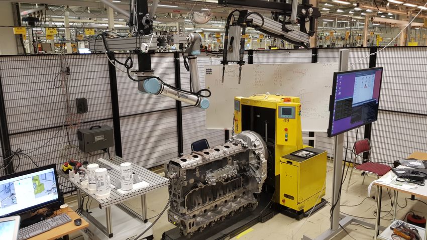
eled as abilities. Abilities are modeled per-resource and Fig. 4. The smart nutrunner fastening the cover plate. Here
interactions between them are defined by specifications. operated by the UR10.
A. Abilities Consider again the smart nutrunner. The smart nu-
An ability models a single task that a resource can trunner is used to bolt down a cover plate onto the
perform. To track the state of an ability during execu- engine, as is shown in Figure 4. An ability, runNut (arn ),
tion, three boolean state variables are defined: isEnabled that models the task of tightening a pair of bolts can
(denoted ai for an ability a), isExecuting (ae ), as well as be defined as follows. To be enabled, the tool should be
isFinished (af ). A set of transitions define how an ability in its isEnabled state which can be reached by taking
updates the system variables. ab↑ and ab↓ denotes the the transition ab→i : ¬tf? ∧ ti? /airn := true. When in
event corresponding to the transitions taken when start- this state, the start transition a↑rn : airn /tf! := true ∧
ing and finishing the ability, respectively. Transitions to ti! := f alse updates the output states required to start
update the state of the ability, with the corresponding the tool. Writing to these output state variables will,after passing through the pipeline transformation steps together with a set of global specifications can be used
outlined in layer 0, eventually produce a message to the to formulate a supervisor synthesis problem directly ap-
nutrunner topic on the ROS2 network. The transition plicable to the EFA model. Using the method described
ab→e : tf? ∧ ¬ti? ∧ ¬ttr? /aern := true synchronizes the in [20], the solution to this synthesis problem can be
executing state of the ability with the measured state, obtained as additional guards on the starting transition
setting aern := true if the tool is running forward and of the abilities. Examples of this modeling technique can
the pre-programmed torque has not yet been reached, as be found in [21], [22]. By keeping specifications as part of
well as setting aern := f alse when the this is not true. the model, there are fewer points of change which makes
The desired result of running the ability is to tighten for faster and less error-prone development compared to
a pair of bolts. As there are no sensors for keeping changing the guard expressions manually.
track of the bolts, the estimated state variable b̂ ∈ For this case, a safety specification is added: when the
(empty, placed, tightened) is introduced. When the abil- robot is guiding the smart nutrunner to tighten a pair
ity is executing and the programmed torque has been of bolts (see Figure 4), it is important that the runNut
reached the tool should stop running forward, and b̂ ability has started before moving down towards the cover
should be updated to ’tightened’. This is modeled in the plate, otherwise the tool will collide with the bolt. This
transition a↓rn : aern ∧ ttr? /ti! := true ∧ tf! := f alse ∧ b̂ = can be modeled as the forbidden state specification up ! =
tightened. bp ∧ b̂ = placed ∧ ¬aern , where bp is the robot pose at the
The effects of the ability are as!! rn : tf! ∧ ¬ti! /tf? := bolt location. It tells the system that it is forbidden for
true∧ti? := f alse, indicating that the tool is expected to the robot to be at position bp when an untightened pair
start running forward after starting the ability and ae!! rn : of bolts is in place and the runNut ability has not been
tf? ∧ ¬ti? /ttr? := true, indicating that during execution started.
of the ability, the programmed torque is expected to
eventually be reached. VII. Layer 2 - Production operations
For the UR10 a parameterized ability is defined: While layer 1 define all possibilities of what the system
moveToPosition, aum(p) which takes a goal position can safely do, layer 2 concerns making the system do
(up !) as an input. As the node runs both the robot something “good”. For this use case it is to bolt the
driver and the MoveIt! planning system, additional cover plate onto the engine. To achieve this, the high level
abilities are introduced: attachInPlanningScene and production operation TightenBoltPair will be defined
detachInPlanningScene, which sends the appropriate in this section.
messages to MoveIt! for setting up the motion planning In SP, production operations are modeled as goal
scene. states. The goal states are defined as predicates over the
Additionally a restart ability is introduced for the system state. For the operation TightenBoltPair, the
robot, moveToPrevious, which is enabled if the robot is goal state is b̂ = tightened, i.e. the estimated bolt state
not moving, its current position is an unknown position should end up being ’tightened’. It also makes sense for
and its previous position is a known position. Restart the operations to have a precondition which ensures that
abilities are only enabled during restart mode as de- the goal state is only activated when it makes sense. For
scribed in Section VIII-A. this operation the precondition is b̂ = placed.
Finally, the human operator is modeled. The opera- Modeling the production operations in this way does
tor’s role is to place bolts coming on the kitting AGV two things. First, it makes it possible to add and remove
onto the cover plate. The human operator informs the resources from the system more easily - as long as the
system that he or she is finished with the task by desired goals can be reached, the upper layers of the
acknowledging this on a smart watch. An ability for the control system does not need to be changed. Second, it
operator, placeBolt, is defined that updates b̂ to ’placed’ makes it easier to model on a high level, eliminating the
during its finish transition. need to care about specific sequences of abilities.
Computing a plan for reaching a goal is done by
B. Specification finding a counter example using bounded model checking
The abilities defined so far, combined with the un- (BMC) [23] on the EFA model of layer 1 (i.e. production
derlying transformation pipelines, can be used to run operations can never start each other). Modern SAT-
the system in an open loop fashion. As we have seen, based model checkers are very efficient in finding counter
the abilities are modeled on a per-resource basis, which examples, even for systems with hundreds of variables.
allow individual testing of their behavior. However, the BMC also has the useful property that counter examples
complexities of developing an automation system arise in have minimal length due to how the problem is un-
the interaction of the different resources. folded into SAT problems iteratively. Additionally, well-
In order to be able to work with individual devices, known and powerful specification languages like Linear
as well as isolating the complexities which arise from Temporal Logic (LTL) [24] can be used. Being able to
their different interactions SP relies heavily on modeling specify LTL properties means that operations can also
using global specifications. The abilities defined so far, contain local specification that should be active wheneverthe operation is executing. For example, reaching the never desirable to be forced to reset individual devices
state defined by the predicate φgood while avoiding the to get back to a known state.
state defined by the predicate φbad can be written as Given this, it is not unlikely that restart errors can
¬φbad U φgood . In the current implementation of SP, the be solved by re-planning. For example if the robot went
SAT based bounded model checking capabilities of the offline, it is probable that the planner can find a way for
nuXmv symbolic model checker [25] is used, but planning the operator to perform the tasks instead. If this fails, SP
engines based on PDDL [26] could be plugged in as well. can enter a restart mode, where the automatic execution
of operations is paused. In this mode, operations can be
VIII. Control implementation reset, where instead of planning to reach the goal state
The system is executed synchronously based on the of the operation, the aim is to reach a state in which
state of all connected resources. Operations execute when its precondition is satisfied. After a successful reset the
their preconditions are satisfied. The goals of each cur- operation can be started again. In this restart mode, it is
rently active operation are conjuncted to form a planning possible to activate a number of restart abilities during
n
V planning. A restart ability resets a subsystem back to
problem on the form ♦(oi g) for the goal states (oi g)
i=1 a known state from which execution can resume (see
of the currently active operations 1 to n, where ♦ is the moveToPrevious in Section VI-A). Lastly, it is up to an
LTL operator specifying that the predicate eventually operator to bring the estimated state of the system back
becomes true. The result of the planning problem gives a into sync with reality, either by changing the physical
start order of the system’s abilities. Abilities are allowed world (e.g. putting a missing part into place), or by
to execute if their preconditions are satisfied and they changing the system state to reflect the reality.
are the first in the current start order. When abilities
are started, they are popped from the start order and IX. Conclusion
the next one may start if its preconditions are fulfilled. This paper introduced Sequence Planner (SP) as an
This greedy behavior enables multiple abilities to start architecture to model and control ROS2 based collabo-
executing in parallel, in contrast to purely sequential rative and intelligent automation systems. The control
planning frameworks. architecture has been implemented on an industrial as-
Reactivity is crucial in human/robot collaboration – it sembly station. Practical experience during development
should be possible for plans to change on short notice. of the control system for the described use case suggest
By modeling reasonably small tasks for the operations that ROS2 does in fact enable larger scale industrial
in layer 2, planning can be fast enough to be performed automation systems to be built on top of it.
continuously. Plans can then be followed in a receding The layered architecture allows reasoning about pro-
horizon fashion, enabling quick reaction to changes in duction operations independently of which combination
the environment. of resources are used to perform them, but at the same
The execution system keeps track of all the transitions time the low level approach taken to planning and control
in the automation system, defined by the abilities and enables a structured approach for error handling on the
the specifications in layer 1. For example, when an level of individual subsystem state. Compared to more
ability is started, the action of its starting transition is high level planning frameworks, this can make recovery
executed, updating the state of the SP variables. This after errors possible in more scenarios.
state update triggers involved pipelines to assemble new SP is under continuous development here [28]. The
ROS2 messages based on the defined transformations hope is that it could become a tool used by a wider
steps (for example generated variable mappings) in layer audience within the ROS community.
0. At the end of the pipeline the new message is sent out References
on the ROS2 network for the different nodes to process.
[1] R. Alterovitz, S. Koenig, and M. Likhachev, “Robot planning
in the real world: Research challenges and opportunities,” AI
A. Restart situations Magazine, vol. 37, no. 2, pp. 76–84, Summer 2016.
During execution the system will invariably reach an [2] L. Perez, E. Rodriguez, N. Rodriguez, R. Usamentiaga,
and D. F. Garcia, “Robot guidance using machine vision
error, or restart, situation. Given that it is not feasible to techniques in industrial environments: A comparative review,”
measure all state of the system, it is likely that the esti- Sensors, vol. 16, no. 3, 2016. [Online]. Available: http:
mated state will cause out of sync errors (e.g. a tightened //www.mdpi.com/1424-8220/16/3/335
[3] A. Bauer, D. Wollherr, and M. Buss, “Human-robot
bolt will end up in its initial “empty” state after a control collaboration: A survey,” International Journal of Humanoid
system restart). To resynchronize the control system Robotics, vol. 05, no. 01, pp. 47–66, 2008. [Online]. Available:
online an operator needs support from the system, for https://doi.org/10.1142/S0219843608001303
[4] “ROS,” http://www.ros.org, 2019, [Online; accessed 25-Feb-
example, guiding the operator to a precalculated state 2019].
from where restart is safe [27]. SP employs a variety of [5] D. Lu, “The 2018 ROS Metrics Report,” https://discourse.
ways in which to get back into a known state. One of ros.org/t/the-2018-ros-metrics-report/6216/2, 2018, [Online;
accessed 25-Feb-2019].
the most important, however, is also the simplest one: [6] “ROS 2,” https://index.ros.org/doc/ros2/, 2019, [Online; ac-
keeping state machines out of the Level 0 nodes! It is cessed 25-Feb-2019].[7] G. Pardo-Castellote, “Omg data-distribution service: archi- [25] R. Cavada, A. Cimatti, M. Dorigatti, A. Griggio, A. Mariotti,
tectural overview,” in 23rd International Conference on Dis- A. Micheli, S. Mover, M. Roveri, and S. Tonetta, “The nuxmv
tributed Computing Systems Workshops, 2003. Proceedings., symbolic model checker,” in CAV, 2014, pp. 334–342.
May 2003, pp. 200–206. [26] M. Fox and D. Long, “Pddl2. 1: An extension to pddl for
[8] M. Cashmore, M. Fox, D. Long, D. Magazzeni, B. Ridder, expressing temporal planning domains,” Journal of artificial
A. Carreraa, N. Palomeras, N. Hurtós, and M. Carrerasa, intelligence research, vol. 20, pp. 61–124, 2003.
“Rosplan: Planning in the robot operating system,” in Pro- [27] P. Bergagård and M. Fabian, “Calculating restart states for
ceedings of the Twenty-Fifth International Conference on In- systems modeled by operations using supervisory control the-
ternational Conference on Automated Planning and Schedul- ory,” Machines, vol. 1, no. 3, pp. 116–141, 2013.
ing, ser. ICAPS’15. AAAI Press, 2015, pp. 333–341. [28] “Sequence Planner,” https://github.com/sequenceplanner,
[9] F. Rovida, M. Crosby, D. Holz, A. S. Polydoros, B. Großmann, 2019, [Online; accessed 1-Mar-2019].
R. P. A. Petrick, and V. Krüger, SkiROS—A Skill-Based
Robot Control Platform on Top of ROS. Cham: Springer
International Publishing, 2017, pp. 121–160.
[10] E. Aertbeliën and J. De Schutter, “etasl/etc: A constraint-
based task specification language and robot controller using
expression graphs,” in 2014 IEEE/RSJ International Confer-
ence on Intelligent Robots and Systems, Sep. 2014, pp. 1540–
1546.
[11] C. Paxton, A. Hundt, F. Jonathan, K. Guerin, and G. D.
Hager, “Costar: Instructing collaborative robots with behavior
trees and vision,” in 2017 IEEE International Conference on
Robotics and Automation (ICRA), May 2017, pp. 564–571.
[12] E. Endre, M. Dahl, H. Atieh, and K. Bengtsson, “A ros2 based
communication architecture for control in collaborative and
intelligent automationsystems,” in Submitted to the 29th In-
ternational Conference on Flexible Automation and Intelligent
Manufacturing (FAIM2019), June 2019.
[13] P. Bellavista, A. Corradi, L. Foschini, and A. Pernafini, “Data
distribution service (dds): A performance comparison of open-
splice and rti implementations,” in 2013 IEEE Symposium
on Computers and Communications (ISCC), July 2013, pp.
000 377–000 383.
[14] M. Sköldstam, K. Åkesson, and M. Fabian, “Modeling of
discrete event systems using finite automata with variables,”
in Decision and Control, 2007 46th IEEE Conference on.
IEEE, 2007, pp. 3387–3392.
[15] P. Bergagård and M. Fabian, “Deadlock avoidance for multi-
product manufacturing systems modeled as sequences of oper-
ations,” in 2012 IEEE International Conference on Automa-
tion Science and Engineering: Green Automation Toward a
Sustainable Society, CASE 2012, Seoul, 20-24 August 2012,
2012, pp. 515 – 520.
[16] N. Sundström, O. Wigström, P. Falkman, and B. Lennart-
son, “Optimization of operation sequences using constraint
programming,” IFAC Proceedings Volumes, vol. 45, no. 6, pp.
1580 – 1585, 2012.
[17] K. Bengtsson, B. Lennartson, and C. Yuan, “The origin of
operations: Interactions between the product and the manu-
facturing automation control system,” IFAC Proceedings Vol-
umes, vol. 42, no. 4, pp. 40–45, 2009.
[18] I. A. Sucan and S. Chitta, “MoveIt!” http://moveit.ros.org,
2018, [Online; accessed 26-Feb-2019].
[19] V. Klang, R. Kuhn, and J. Bonér, “Akka library.” http://akka.
io, 2018, [Online; accessed 26-Feb-2019].
[20] S. Miremadi, B. Lennartson, and K. Åkesson, “A BDD-based
approach for modeling plant and supervisor by extended finite
automata,” Control Syst. Technol. IEEE Trans., vol. 20, no. 6,
pp. 1421–1435, 2012.
[21] P. Bergagård, P. Falkman, and M. Fabian, “Modeling and
automatic calculation of restart states for an industrial wind-
screen mounting station,” IFAC-PapersOnLine, vol. 48, no. 3,
pp. 1030–1036, 2015.
[22] M. Dahl, K. Bengtsson, M. Fabian, and P. Falkman, “Auto-
matic modeling and simulation of robot program behavior in
integrated virtual preparation and commissioning,” Procedia
Manufacturing, vol. 11, pp. 284–291, 2017.
[23] A. Biere, A. Cimatti, E. Clarke, and Y. Zhu, “Symbolic model
checking without bdds,” in International conference on tools
and algorithms for the construction and analysis of systems.
Springer, 1999, pp. 193–207.
[24] A. Pnueli, “The temporal logic of programs,” in 18th Annual
Symposium on Foundations of Computer Science (sfcs 1977).
IEEE, 1977, pp. 46–57.You can also read