FTV (Free viewpoint TV) and Creation of Ray-Based Image Engineering
←
→
Page content transcription
If your browser does not render page correctly, please read the page content below
FTV (Free viewpoint TV) and Creation of Ray-Based Image Engineering                                                  1

     FTV (Free viewpoint TV) and Creation of
          Ray-Based Image Engineering
                                     Masayuki Tanimoto 1 , Non-member

ABSTRACT                                                          We proposed the concept of FTV and verified its
                                                               feasibility with the world’s first real-time experiment
   Free viewpoint TV (FTV) enables us to view a dis-
                                                               [11],[12], in which a real, moving object was viewed
tant 3D world by freely changing our viewpoints as if
                                                               using a virtual bird’s-eye camera whose position was
we were there. FTV will bring an epochal change
                                                               moved freely in a space and was controlled by a 3D
in the history of television since this function has
                                                               mouse.
not yet been achieved by conventional TV technol-
ogy. We proposed the concept of FTV and verified                  FTV opens a new frontier in the field of signal
its feasibility using the world’s first real-time system       processing since its process such as coding and image
including the complete chain of operation from image           generation is performed in the ray-space, a new do-
capture to display. The international standardization          main with higher dimensionality than possible with
of FTV technologies is now underway. FTV is a ray-             conventional TV. A new user interface is also needed
based system rather than a pixel-based system. We              for FTV to make full use of 3D information.
are creating ray-based image engineering through the
development of FTV.                                               As the ultimate 3D-TV, FTV needs higher perfor-
                                                               mance in all related devices, equipment and systems,
1. INTRODUCTION                                                as well as accelerated development of the electronics
                                                               industry. As the next-generation TV, it will find ap-
   Television realized the human dream of seeing a
                                                               plications in the fields of communication, entertain-
distant world in real time and has served as the most
                                                               ment, advertising, education, medicine, art, archives
important visual information technology to date.
                                                               and so on. As part of the social information infras-
Now, television can provide us scenes overcoming dis-
                                                               tructure, it can increase the security of public facili-
tance not only in space but also in time by intro-
                                                               ties, roads, vehicles, schools, factories, etc.
ducing storage devices into television. However, TV
shows us the same scene even if we change our view-               The FTV Committee has been organized to pro-
point in front of the display. This is quite different         mote the international standardization of FTV in the
from what we experience in the real world. With                Japan Electronics and Information Technology Indus-
TV, users can get only a single view of a 3D world.            tries Association (JEITA) under the support of the
The view is determined not by users but by a camera            Ministry of Economy, Trade and Industry (METI).
placed in the 3D world. Although many important                About 20 organizations participate in this activity,
technologies have been developed, this function of TV          including members of industry, carriers, broadcasters,
has never changed.                                             and content providers. We proposed FTV to MPEG
   We have developed a new type of television named            (Moving Picture Experts Group) [13] and have been
FTV (Free viewpoint TV) [1]-[6]. FTV is an innova-             making contributions to its development. It is consid-
tive visual media that enables us to view a 3D scene           ered the most challenging scenario in the 3DAV (3D
by freely changing our viewpoints as if we were there.         Audio Visual) work of MPEG, and the standardiza-
FTV will bring an epochal change in the history of             tion of MVC (Multi-view Video Coding) has started
visual media since such a function has not yet been            [14].
achieved by conventional media technology. FTV is
based on the ray-space method [7] - [10].                         MPEG and ITU-T (International Telecommunica-
   The most essential element of visual systems is not         tion Union Telecommunication Standardization Sec-
the pixel but the ray. FTV is not a conventional               tor) have started the standardization of the entire
pixel-based system but a ray-based system. We have             FTV [15] because the FTV system cannot be achieved
been developing ray capture, processing, and display           by multi-view video coding alone. This activity is
technologies for FTV [4].                                      supported by the SCOPE-I program of the Ministry
                                                               of Internal Affairs and Communications (MIC).
  Manuscript received on January 1, 2009 ; revised on August
1, 2009.                                                          In this paper, the principle, basic technologies and
  1 The author is with Graduate School of Engineer-
                                                               advanced ray technologies of FTV are presented. The
ing, Nagoya University Furo-cho, Chikusa-ku, Nagoya, 464-
8603, Japan, E-mail: tanimototentative3@yahoo.co.jp and        progress of international standardization of FTV is
tanimoto@nuee.nagoya-u.ac.jp                                   also described.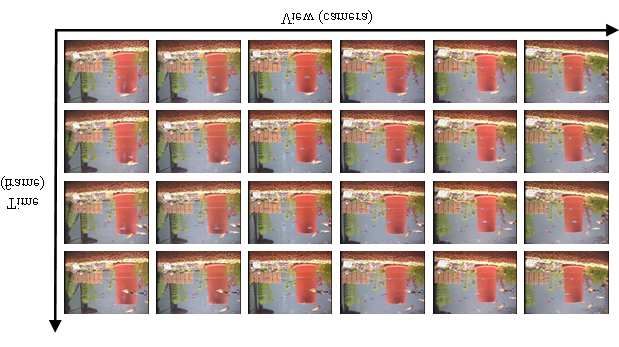
2       ECTI TRANSACTIONS ON ELECTRICAL ENG., ELECTRONICS, AND COMMUNICATIONS VOL.7, NO.2 August 2009

2. RAY-SPACE REPRESENTATION
   We developed FTV based on ray-space represen-
tation [8] - [11]. In ray-space representation, one ray
in the 3D real space is represented by one point in
the ray space. The ray space is a virtual space. How-
ever, it is directly connected to the real space. The
ray space is generated easily by collecting multi-view
images while giving consideration to the camera pa-
rameters.                                                         Fig.3: Camera Arrangements for FTV
   Let (x, y, z) be three space coordinates and θ, φ
be the parameters of direction. A ray going through
space can be uniquely parameterized by its location
(x, y, z) and its direction (θ, φ); in other words, a ray
can be mapped to a point in this 5D, ray-parameter
space. In this ray-parameter space, we introduce the
function f , whose value corresponds to the intensity
of a specified ray. Thus, all the intensity data of rays
can be expressed by

                f (x, y, z; θ, φ)
          −π ≤ θ < π, −π/2 ≤ φ < π/2                 (1)        Fig.4: Acquisition of orthogonal ray-space

                                                            intersection of the ray and the reference plane and
                                                            the ray’s direction as shown in Fig. 1. Another is
                                                            the spherical ray-space, where the reference plane is
                                                            set to be normal to the ray as shown in Fig. 2. The
                                                            orthogonal ray-space is used for FTV with a linear
                                                            camera arrangement, whereas the spherical ray-space
                                                            is used for FTV with a circular camera arrangement.
                                                            The linear camera arrangement is used for parallel
                                                            view and the circular camera arrangement is used for
                                                            convergent view as shown in Fig. 3.
     Fig.1: Definition of orthogonal ray-space                 Both the orthogonal ray-space and the spherical
                                                            ray-space are 4D and 5D, including time. If we place
                                                            cameras within a limited region, the obtained rays
                                                            are limited, and the ray-space constructed from these
                                                            rays is a subspace of the ray-space. For example, if
                                                            we place cameras in a line or in a circle, we have only
                                                            one part of the data of the whole ray-space. In such
                                                            cases, we define a smaller ray-space.

      Fig.2: Definition of spherical ray-space

    Although the 5D ray-space mentioned above in-
cludes all information viewed from any viewpoint, it              Fig.5: Example of orthogonal ray-space
is highly redundant due to the straight traveling paths
of the rays. Thus, when we treat rays that arrive at           For the linear camera arrangement, the ray-space
a reference plane, we can reduce the dimension of the       is constructed by placing many camera images up-
parameter space to 4D.                                      right and parallel, as shown in Fig. 4, forming the
    We use two types of ray-space for FTV. One is the       FTV signal in this case. The FTV signal consists of
orthogonal ray-space, where a ray is expressed by the       many camera images, and the horizontal cross-section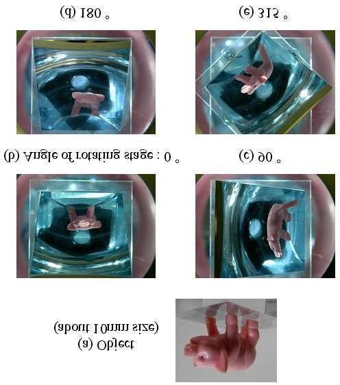
FTV (Free viewpoint TV) and Creation of Ray-Based Image Engineering                                                  3

                                                               Fig.9: Free viewpoint image generation at various
                                                               distances using hierarchical ray-space

          Fig.6: Generation of view images
                                                               3. FTV SYSTEM
                                                               3. 1 Configuration of FTV System
                                                                  Fig. 10 shows the configuration of the FTV sys-
                                                               tem. At the sender side, a 3D scene is captured
                                                               by multiple cameras. The captured images contain
                                                               the misalignment and luminance differences of the
                                                               cameras. They must be corrected to construct the
                                                               ray-space. The corrected images are compressed for
                                                               transmission and storage by the MVC (Multi-view
                                                               Video Coding) encoder.
                                                                  At the receiver side, reconstructed images are ob-
       Fig.7: Example of spherical ray-space                   tained by the MVC decoder. The ray-space is con-
                                                               structed by arranging the reconstructed images and
                                                               interpolating them. Free-viewpoint images are gener-
has a line structure as shown in Fig. 5. The line              ated by cutting the ray-space vertically and are dis-
structure of the ray-space is used for ray-space inter-        played on a 2D/3D display.
polation and compression. Vertical cross-sections of              The function of FTV was successfully demon-
the ray-space give view images at the corresponding            strated by generating photo-realistic, free-viewpoint
viewpoints as shown in Fig. 6.                                 images of the moving scene in real time. Each part of
   For the circular camera arrangement, the spherical          the process shown in Fig. 10 is explained in greater
ray-space is constructed from many camera images,              detail below.
and its horizontal cross-section has a sinusoidal struc-
ture as shown in Fig. 7. The sinusoidal structure of
the ray-space is also used for ray-space interpolation
and compression.
   The hierarchical ray-space [10] is defined for scal-
able expression of 3D scene. Fig. 8 shows the concept
of the hierarchical ray-space. Fig. 9 shows free view-
point image generation at various distances using the                 Fig.10: Configuration of FTV system
hierarchical ray-space.

                                                               3. 2 Capture
                                                                  We constructed a 1D-arc capturing system shown
                                                               in Fig. 11 for a real-time FTV system covering the
                                                               complete chain of operation from video capture to
                                                               display [16]. It consists of 16 cameras, 16 clients and
                                                               1 server. Each client has one camera and all clients
                                                               are connected to the server with Gigabit Ethernet.
                                                                  A “100-camera system” has been developed to cap-
                                                               ture larger space by Nagoya University (Intelligent
                                                               Media Integration COE and Tanimoto Laboratory)
                                                               [17]. The system consists of one host-server PC and
                                                               100 client PCs (called ’nodes’) that are equipped with
                                                               JAI PULNiX TM-1400CL cameras. The interface be-
      Fig.8: Concept of hierarchical ray-space                 tween camera and PC is Camera-Link. The host PC
                                                               generates a synchronization signal and distributes it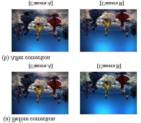
4 ECTI TRANSACTIONS ON ELECTRICAL ENG., ELECTRONICS, AND COMMUNICATIONS VOL.7, NO.2 August 2009
to all of the nodes. This system is capable of cap-
turing not only high-resolution video with 30 fps but
also analog signals of up to 96 kHz. The specification
of the 100-camera system is listed in table 1.
The camera setting is flexible as shown in Fig. 12.
MPEG test sequences “Rena” and “Akko & Kayo”
shown in Fig. 13 were taken by camera arrangements (a) “Rena” (b) “Akko & Kayo”
(a) and (c), respectively.
Fig.13: MPEG test sequences
An example of the geometric correction is shown
in Fig. 14 [19]. Here, the geometric distortion of a
2 dimensional camera array is corrected by the affine
transform. It is seen that the trajectory of correspon-
dence point becomes square by the geometric correc-
tion.
Fig.11: 1D-arc capturing system An example of color correction is shown in Fig. 15.
Table 1: Specification of 100-camera system
Image resolution 1392(H)x1040(V)
Frame rate 29.4118 [fps]
Color Bayer matrix
Synchronization Less than 1 [us]
Sampling rate of A/D 96 [kS/s] maximum
Maximum number of nodes No limit.
(128 max for one sync output)
Fig.14: An example of geometric correction
(a) linear arrangement
(b) circular arrangement
Fig.15: An example of color correction
(c) 2D-array arrangement
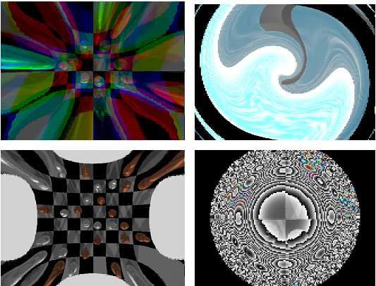
Fig.12: 100-camera system 3. 4 MVC Encoding and Decoding
An example of time and view variations of multi-
view images is shown in Fig. 16. They have high
3. 3 Correction
temporal and interview correlations. MVC (Multi-
The geometric correction [18], [19] and color cor- view Video Coding) reduces these correlations [14],
rection [20] of multi-camera images are performed by [21], [22]. The standardization of multi-camera im-
measuring the correspondence points of images. This age compression is progressing with MVC (Multi-
measurement is made once the cameras are set. view Video Coding) in MPEG. Details are described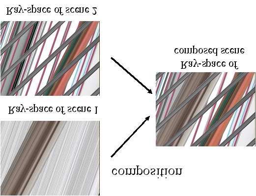
FTV (Free viewpoint TV) and Creation of Ray-Based Image Engineering                                                  5

in Section 5.                                                     Viewpoint control by head-tracking is shown here.
                                                               Many head-tracking systems have been proposed us-
                                                               ing magnetic sensors, various optical markers, in-
                                                               frared cameras, retroreflective light from retinas, etc.
                                                               Our head-tracking system uses only a conventional
                                                               2D camera and detects the position of a user’s head
                                                               by image processing. The user doesn’t need to attach
                                                               any markers or sensors.
                                                                  In the user interface using a 2D display, the lo-
                                                               cation of the user’s head is detected with the head-
                                                               tracking system and the corresponding view image is
                                                               generated. Then, it is displayed on the 2D display as
                                                               shown in Fig. 19.
Fig.16: Time and view variations of multi-view im-                Automultiscopic displays enable a user to see
ages                                                           stereoscopic images without special glasses. However,
                                                               there are two problems: a limited viewing zone and
                                                               discreteness of motion parallax. Because the width of
                                                               the viewing zone for each view approximates the in-
3. 5 View Generation                                           terpupillary distance, the view image does not change
   Ray-space is formed by placing the reconstructed            with the viewer’s movement within the zone. On the
images vertically and interpolating them. Free-                other hand, when the viewer moves over the zone, the
viewpoint images are generated by making a cross-              view image changes suddenly.
section of the ray-space.                                         In the user interface using the automultiscopic dis-
                                                               play, the function of providing motion parallax is ex-
   Examples of the generated free-viewpoint images
                                                               tended by using the head-tracking system. The im-
are shown in Fig. 17. Complicated natural scenes,
                                                               ages fed to the system change according to the move-
including sophisticated objects such as small moving
                                                               ment of the head position to provide small motion
fish, bubbles and reflections of light from aquarium
                                                               parallax, and the view channel for feeding the images
glass, are reproduced very well.
                                                               is switched for handling large motion. This means
                                                               that binocular parallax for the eyes is provided by
                                                               automultiscopic display, while motion parallax is pro-
                                                               vided by head tracking and changing the image adap-
                                                               tively as shown in Fig. 20.

Fig.17: An example of generated FTV images at
various times and viewpoints

   The quality of the generated view images depends
on the view interpolation. The ray-space interpola-
tion is achieved by detecting depth information pixel
by pixel from the multi-view video. We proposed sev-                         Fig.18: Display of FTV
eral interpolation schemes of the ray-space [23]-[28].
   The free-viewpoint images were generated by a PC
cluster in [16]. Now, they can be generated by a single        4. CREATION OF RAY-BASED IMAGE
PC, and FTV on a PC can be accomplished in real                   ENGINEERING
time [27].
                                                               4. 1 Evolution of Image Systems
                                                                  Fig. 21 shows the evolution of image systems. In
3. 6 2D/3D Display
                                                               the past, image systems such as photography, film
   FTV needs a new user interface to display free-             and TV were individual systems. At present, they are
viewpoint images. Two types of display, 3D display             digitized and can be treated on the same platform as
and 2D/3D display with a viewpoint controller, are             pixel-based systems. These pixel-based systems are
used for FTV as shown in Fig. 18.                              developing toward using more pixels. This trend is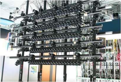
6         ECTI TRANSACTIONS ON ELECTRICAL ENG., ELECTRONICS, AND COMMUNICATIONS VOL.7, NO.2 August 2009

                                                        used instead of multiple cameras. The important fea-
                                                        ture of this configuration is that the spatial density of
                                                        a multi-camera setup is converted to a time-density
                                                        axis, i.e. the frame rate of the camera. This means
                                                        that we can increase the density of the camera inter-
                                                        val equivalently by increasing the frame rate of the
                                                        camera. The scanning optical system is composed of
                                                        a double-hyperbolic mirror shell and a galvanomet-
                                                        ric mirror. The mirror shell produces a real image of
                                                        an object that is placed at the bottom of the shell.
         Fig.19: 2D display with eye tracking           The galvanometric mirror in the real image reflects
                                                        the image in the camera-axis direction. The reflected
                                                        image observed from the camera varies according to
                                                        the angle of the galvanometric mirror. This means
                                                        that the camera can capture the object from various
                                                        viewing directions that are determined by the angle
                                                        of the galvanometric mirror. To capture the time-
                                                        varying reflected images, we use a high-speed camera
                                                        with an electronic shutter that is synchronized with
    (a)without head tracking   (b)with head tracking    the angle of the galvanometric mirror. We capture
                                                        more than 100 view images within the reciprocation
Fig.20: 3D display with and without head tracking       time of the galvanometric mirror. The collection of
                                                        the view images is then mapped to the ray-space.
exemplified by Super High-Definition TV [29]. Al-           However, this system can capture the spherical
though Super HDTV has about 100 times the pixels        ray-space with the viewing zone of only 55 degrees.
of SDTV, there is still only one view.                      Then, we have developed a 360-degree ray captur-
   In the future, the demand for more pixels will be    ing system as shown in Fig. 23 [31], [32]. This sys-
saturated, and more views will be needed. This will     tem uses two parabolic mirrors. Incident rays that
result in the evolution from a pixel-based system to    are parallel to the axis of a parabolic mirror gather
a ray-based system. We have been developing FTV         at the focus of the parabolic mirror. Hence, rays that
according to this scenario. Roughly speaking, we can    come out of an object placed at the focus of the lower
achieve SD-FTV by using the technologies of HDTV        parabolic mirror gather at the focus of the upper
or Super HDTV and balancing the number of pixels        parabolic mirror. Then, the real image of the object
and views.                                              is generated at the focus of the upper parabolic mirror
                                                        and a rotating aslope mirror scans rays at the focus of
                                                        the upper parabolic mirror. Finally, the image from
                                                        the aslope mirror is captured by a high-speed cam-
                                                        era. By using this system, we can capture all-around
                                                        convergent views of an object as shown in Fig. 24.

          Fig.21: Evolution of image systems

                                                             Fig.22: Mirror-scan ray capturing system
4. 2 Ray Capture and Display
   We are developing ray-reproducing FTV to create         Fig. 25 shows SeeLINDER [33], a 360-degree, ray-
ray-based image engineering. Ray-reproducing FTV        producing display that allows multiple viewers to see
consists of ray capture, ray processing and ray dis-    3D FTV images. Structure of the SeeLinder is shown
play.                                                   in Fig. 26. It consists of a cylindrical parallax barrier
   We developed a ray capturing system [30] shown       and one-dimensional light-source arrays. Semicon-
in Fig. 22. It acquires a dense ray-space without in-   ductor light sources such as LEDs are aligned verti-
terpolation in real time. In this capturing system, a   cally for the one-dimensional light-source arrays. The
high-speed camera and a scanning optical system are     cylindrical parallax barrier rotates quickly, and the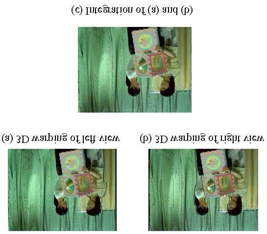
FTV (Free viewpoint TV) and Creation of Ray-Based Image Engineering                                                  7

                                                               position. Therefore, we perceive the objects just as if
                                                               they were floating in the cylinder.
                                                                  We are going to connect these two systems directly
                                                               in real time.

Fig.23:    360-degree mirror-scan ray capturing sys-
tem                                                            Fig.25:     The SeeLINDER, a 360 degree, ray-
                                                               reproducing display

                                                                       Fig.26: Structure of the SeeLinder

                                                                  Fig. 27 shows the progress made in 3D captur-
                                                               ing and display systems. In this figure, the ability of
                                                               3D capturing and display is expressed as a factor of
                                                               the pixel-view product, defined as (number of pixels)
Fig.24: Object and captured images of 360-degree               ×(number of views). In Fig. 27, (1) denotes the fac-
ray capturing system                                           tor of the 100-camera system mentioned earlier. We
                                                               have also been developing new types of ray-capturing
                                                               and display systems. Their factors are indicated by
light-source arrays rotate slowly in the opposite di-          (2) and (3); (2) is a mirror-scan ray-capturing sys-
rection. If the aperture width of the parallax barrier         tem [30] and (3)is the 360-degree, ray-reproducing
is sufficiently small, the light going through the aper-       SeeLINDER display [33].
ture becomes a thin flux, and its direction is scanned            In Fig. 27, the progress of space-multiplexing dis-
by the movement of the parallax barrier and the light-         plays follows Moore’s Law because it is achieved by
source arrays. By synchronously changing the in-               miniaturization. The factor of the time-multiplexing
tensity of the light sources with the scanning, pix-           display is larger than that of the space-multiplexing
els whose luminance differs for each viewing direction         display. The difference is a result of time-multiplexing
can be displayed. We can see the 3D image naturally,           technology. The progress of capturing does not follow
and the images have the strong depth cues of natural           Moore’s Law because it depends on camera resolution
binocular disparity. When we move around the dis-              and the number of cameras used. Furthermore, the
play, the image changes corresponding to our viewing           pixel-view product has increased very rapidly year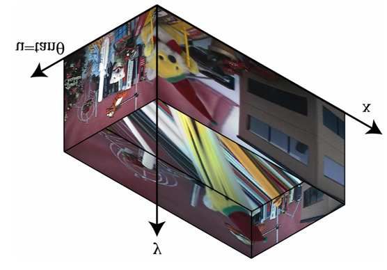
8       ECTI TRANSACTIONS ON ELECTRICAL ENG., ELECTRONICS, AND COMMUNICATIONS VOL.7, NO.2 August 2009

after year in both capture and display. This develop-
ment strongly supports our scenario.

                                                          Fig.28: Typical example of orthogonal ray-space and
                                                          a horizontal cross-section

Fig.27: Progress in increasing pixel-view product for
3D capturing and display

4. 3 Ray Processing
   Typical example of orthogonal ray-space with a                (a)Before filtering   (b)After filtering
horizontal cross-section is shown in Fig. 28. The hor-
izontal cross-section has a line structure. The slope     Fig.29: An example of ray-space processing: object
of the line corresponds to the depth of object.           elimination by non-linear filtering.
   The ray-space is a platform of ray processing. Vari-
ous kinds of signal processing can be done in the ray-
space. Vertical cross-sections of the ray-space give
real view images at the corresponding viewpoints.
Manipulation, division and composition of 3D scenes
are also performed by ray-space processing.
   Fig. 29 shows an example of the ray-space process-
ing. Bars in the scene of Fig. 29 (a) are eliminated
in Fig. 29 (b) by applying non-linear filtering to the
ray-space [34]. Composition of 2 scenes shown in Fig.
30 is performed by ray-space processing as shown in
Fig. 31 [35].
   Images with optical effects are generated by cut-
ting the ray-space with a curved plane as shown in
Fig. 32. The shape of the curved plane is determined
                                                          Fig.30: Scene composition by ray-space processing
due to an optical effect to be realized. Artistic im-
ages shown in Fig. 33 are generated by cutting the
ray-space with more general planes [36], [37].

5. INTERNATIONAL STANDARDIZATION
   Figure 34 shows standardization activities of
3DAV/MVC/FTV in MPEG. MPEG established
AHG on 3DAV (3D Audio Visual) and started 3DAV
activities in December 2001. We proposed FTV to
MPEG in July 2002 [13]. In the first stage, many
3D topics were discussed. In particular, the following
four topics were studied intensively as EEs (Explo-
ration Experiments).
   EE1: omnidirectional video
   EE2: free viewpoint                                    Fig.31: Ray-space processing for scene composition
            -FTV (Ray-Space)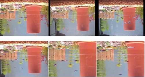
FTV (Free viewpoint TV) and Creation of Ray-Based Image Engineering                                                  9

                                                               established AHG on FTV [15] for the standardization
                                                               of FTV in April 2007 and issued “Preliminary FTV
                                                               Model and Requirements” [45].
                                                                  In October 2007, the scope of MPEG-FTV was ex-
                                                               tended to cover MVC and SSV (Stereoscopic Video)
                                                               and a document “Applications and Requirements on
                                                               FTV” [46] was issued. This document combines
                                                               the applications and requirements of FTV, SSV and
                                                               MVC to keep the consistency of the larger scope of
                                                               FTV project.
                                                                  As shown in Fig. 35, FTV system can be con-
Fig.32: Cutting ray-space with curved planes for               structed in various ways, depending on the location
image generation with optical effects                          of depth search and interpolation. FTV data formats
                                                               for the 3 cases are shown in Fig. 36. MPEG selected
                                                               Case B where depth search is performed at sender
                                                               side and interpolation is performed at receiver side.
                                                               Depth can be estimated from multi-view video or can
                                                               be measured [47]. This configuration is suitable for
                                                               the download/package and broadcast services since
                                                               processing at sender side is heavy and processing at
                                                               receiver side is light.
                                                                  Figure 37 shows the FTV reference model [45]
                                                               and standardization items. Transmission data format
                                                               and protocol are discussed at ITU-T (International
                                                               Telecommunication Union Telecommunication Stan-
                                                               dardization Sector). At the sender side of the FTV
                                                               reference model, multi-view images are captured by
Fig.33: Examples of artistic images generated by               multiple cameras. The captured images contain the
cutting the ray-space with more general planes                 misalignment and color differences of the cameras.
                                                               They are corrected and the depth of each camera
                                                               image is obtained. The corrected multi-view images
           -FVV (model based)                                  and multi-view depth are compressed for transmission
   EE3: stereoscopic video                                     and storage by the encoder. At the receiver side, the
   EE4: 3D-TV with depth disparity information                 multi-view images and multi-view depth are recon-
   EE2 was established due to our proposal of FTV.             structed by the decoder. Free-viewpoint images are
The discussion was focused on FTV and its coding               generated by interpolating the reconstructed images
part (MVC, Multi-view Video Coding) in January                 using multi-view depth information and displayed on
2004 because FTV got strong support from indus-                a 2D/3D display.
try in response to the “Call for Comments on 3DAV”                An example of intermediate view generation by in-
[38].                                                          terpolating multi-view images using multi-view depth
   Succeeding in “Call for Evidence on Multi-view              is shown in Fig. 38 [48]. Compared to the view syn-
Video Coding” [39] led the start of standardization of         thesis by using one view and one depth, the number
MVC in January 2005. ”Call for Proposals on Multi-             of pixels which are not filled is greatly reduced. Es-
view Video Coding” [40] was issued in July 2005. The           pecially, the occluded area is successfully interpolated
background of MVC is described in [14]. The propos-            by the reliable pixel data.
als were evaluated in January 2006 [41]. The MVC                  Please follow the link to subscribe MPEG-FTV.
activity moved to the Joint Video Team (JVT) of                https://mailman.rwth-aachen.de/mailman/listinfo
MPEG and ITU for further standardization processes             /mpeg-ftv
in July 2006. The standardization of MVC will be fi-
nalized in July 2008 as shown in Table 2. The new
standard of MVC is based on H.264/MPEG4-AVC                           Table 2: Schedule of MVC Standardization
and will be MPEG-4 Part 10, Amd. 4.                                    2006/10 WD(Working Draft)
   The FTV cannot be constructed by coding part                        2007/07 CD(Committee Draft)
alone. We proposed to standardize the entire FTV                       2008/01 FCD(Final Committee Draft)
under the support of SCOPE-I of the Ministry of In-                    2008/07 FDIS (Final Draft International
ternal Affairs and Communications (MIC) [42] and                                Standards
presented the requirements for FTV [43]. The FTV
standardization is supported by industry [44]. MPEG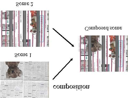
10     ECTI TRANSACTIONS ON ELECTRICAL ENG., ELECTRONICS, AND COMMUNICATIONS VOL.7, NO.2 August 2009

Fig.34: Examples of artistic images generated by
cutting the ray-space with more general planes

                                                    Fig.38: An example of view generation by FTV ref-
                                                    erence model

                                                    6. CONCLUSIONS
                                                        We have developed FTV that enables users to view
                                                    a 3D scene by freely changing the viewpoints. FTV
                                                    is the most advanced visual system and will bring an
                                                    epochal change in the history of television.
                                                        The most essential element of visual systems is ray.
                                                    FTV is not a conventional pixel-based system but a
                                                    ray-based system. FTV needs advanced technologies
Fig.35: 3 cases of FTV configuration based on the   of ray capture, processing and display. We are cre-
positions of depth search and interpolation         ating ray-based image engineering through the devel-
                                                    opment of FTV.
                                                        The international standardization of FTV is now
                                                    underway at MPEG and ITU-T. The introduction of
                                                    FTV is not far because the interactive view genera-
                                                    tion of FTV has already been realized in real time
                                                    on a single PC. Therefore, we can enjoy FTV on PCs
                                                    if the new standard of FTV is available and FTV
                                                    contents are delivered over internet or with packaged
                                                    media.

                                                    7. ACKNOWLEDGEMENT
                                                       We would like to thank JEITA and FTV Com-
     Fig.36: Candidates for FTV data format         mittee members for their support to FTV standard-
                                                    ization activity. This research is partially supported
                                                    by the Ministry of Education, Science, Sports and
                                                    Culture, Grant-in-Aid for Scientific Research (A)
                                                    18206044, and the Ministry of Economy, Trade and
                                                    Industry and the Ministry of Internal Affairs and
                                                    Communications, Strategic Information and Com-
                                                    munications R&D Promotion Programme (SCOPE)
                                                    041306003.

                                                    References
                                                    [1]   M. Tanimoto, “Free Viewpoint Television,” The
                                                          Journal of Three Dimensional Images, vol.15,
Fig.37:   FTV reference model and standardization
                                                          no.3, pp.17-22, September 2001 (in Japanese).
items
                                                    [2]   M. Tanimoto, “Overview of Free Viewpoint Tele-
FTV (Free viewpoint TV) and Creation of Ray-Based Image Engineering 11
vision,” Signal Processing: Image Communica- Conference on Multimedia & Expo (ICME), pp.
tion, vol. 21, no.6, pp.454-461, July 2006 437-440, July 2006.
[3] M. Tanimoto, “Free Viewpoint Television - [18] K. Matsumoto, T. Yendo, T. Fujii and M. Tan-
FTV,” Picture Coding Symposium 2004, Special imoto, “Multiple-Image Rectification for FTV,”
Session 5, December 2004. Proc. of 3D Image Conference 2006, P-19, pp.
[4] Masayuki Tanimoto, “FTV (Free Viewpoint 171-174, July 2006.
Television) Creating Ray-Based Image Engineer- [19] N. Fukushima, T. Yendo, T. Fujii and M. Tan-
ing,” Proc. of ICIP2005, pp. II-25-II-28, Septem- imoto, “A Novel Rectification Method for Two-
ber 2005. Dimensional Camera Array by Parallelizing Lo-
[5] M. Tanimoto, “Free Viewpoint Television,” OSA cus of Feature Points,” Proc. of IWAIT2008, B5-
Topical Meeting on Digital Holography and Three 1, January 2008.
Dimensional Imaging, DWD2, June 2007(In- [20] K. Yamamoto,T. Yendo, T. Fujii and M. Tan-
vited Paper). imoto, “Colour Correction for Multiple-camera
[6] A. Kubota, A. Smolic, M. Magnor, M. Tanimoto, System by using Correspondences,” The journal
T. Chen, and C. Zhang, “Multiview Imaging of the institute of Image Information and Televi-
and 3DTV,” IEEE Signal Processing Magazine, sion Engineers, vol. 61,no. 2, pp.213-222 ,Febru-
Vol.24, No.6, pp.10-21, November 2007. ary 2007
[7] T. Fujii, “A Basic Study on Integrated 3-D Vi- [21] Y. He, J. Ostermann, M. Tanimoto and A.
sual Communication,” Ph.D dissertation in en- Smolic; “Introduction to the Special Section on
gineering, The University of Tokyo, 1994 (in Multiview Video Coding,” IEEE Transactions
Japanese). on Circuits and Systems for Video Technology,
Vol.17, No.11, pp.1433-1435(November 2007).
[8] T. Fujii, T. Kimoto and M. Tanimoto, “Ray
Space Coding for 3D Visual Communication,” [22] K. Yamamoto, M. Kitahara, T. Yendo, T. Fu-
Picture Coding Symposium 1996, pp. 447-451, jii, M. Tanimoto, S. Shimizu, K. Kamikura,
March 1996. and Y. Yashima; “Multiview Video Coding Us-
ing View Interpolation and Color Correction,”
[9] M. Tanimoto, A. Nakanishi, T. Fujii and T. Ki-
IEEE Transactions on Circuits and Systems
moto, “The Hierarchical Ray-Space for Scalable
for Video Technology, Vol.17, No.11, pp.1436-
3-D Image Coding,” Picture Coding Symposium
1449(November 2007).
2001, pp. 81-84, April 2001.
[23] A. Nakanishi, T. Fujii, T. Kimoto and M.
[10] T. Fujii and M. Tanimoto, “Free-viewpoint Tele-
Tanimoto, “Ray-Space Data Interpolation by
vision based on the Ray-Space representation,”
Adaptive Filtering using Locus of Correspond-
Proc. SPIE ITCom 2002, pp. 175-189, August
ing Points on Epipolar Plane Image,” The Jour-
2002.
nal of the Institute of Image Information and
[11] M. Sekitoh, K. Toyota, T. Fujii, T. Kimoto and Television Engineers (ITE), vol. 56, no. 8, pp.
M. Tanimoto, “Virtual Bird’s-Eye View System 1321-1327, August 2002.
based on Real Image,” EVA 2000 Gifu, 8, pp.8-
[24] M. Droese, T. Fujii and M. Tanimoto, “Ray-
1∼8-7, October 2000.
Space Interpolation based on Filtering in Dis-
[12] M. Sekitoh, T. Fujii, T. Kimoto and M. Tan- parity Domain,” Proc. 3D Conference 2004, pp.
imoto, “Bird’s Eye View System for ITS,” 213-216, Tokyo, Japan, June 2004.
IEEE, Intelligent Vehicle Symposium, pp. 119- [25] M. Droese, T. Fujii and M. Tanimoto, “Ray-
123, 2001. Space Interpolation Constraining Smooth Dis-
[13] M. Tanimoto and T. Fujii, “FTV Free View- parities Based On Loopy Belief Propagation,”
point Television”, ISO/IEC JTC1/SC29/WG11, Proc. of IWSSIP 2004, pp. 247-250, Poznan,
M8595, July 2002. Poland, Sept. 2004.
[14] “Introduction to Multi-view Video Coding”, [26] N. Fukushima, T. Yendo, T. Fujii and M. Tan-
ISO/IEC JTC 1/SC 29/WG11, N7328, July imoto, “Real-time arbitrary view interpolation
2005. and rendering system using Ray-Space,” Proc.
[15] “AHG on FTV (Free Viewpoint Television)”, SPIE Three-Dimensional TV, Video, and Dis-
ISO/IEC JTC1/SC29/WG11 N8947, April 2007. play IV, Vol. 6016, pp. 250-261, Nov. 2005.
[16] P. Na Bangchang, T. Fujii and M. Tanimoto, [27] N. Fukushima, T. Yendo, T. Fujii and M.
“Experimental System of Free Viewpoint TeleVi- Tanimoto, “An Effective Partial Interpolation
sion,” Proc. IST/SPIE Symposium on Electronic Method for Ray-Space,” Proc. of 3D Image Con-
Imaging, Vol. 5006-66, pp. 554-563, Jan. 2003. ference 2006, pp. 85-88, July 2006.
[17] T. Fujii, K. Mori, K. Takeda, K. Mase, M. Tan- [28] N. Fukushima, T. Yendo, T. Fujii and M. Tan-
imoto and Y. Suenaga, “Multipoint Measuring imoto, “Free Viewpoint Image Generation Us-
System for Video and Sound: 100-camera and ing Multi-Pass Dynamic Programming,” Proc.
microphone system”, IEEE 2006 International SPIE Stereoscopic Displays and Virtual Reality12 ECTI TRANSACTIONS ON ELECTRICAL ENG., ELECTRONICS, AND COMMUNICATIONS VOL.7, NO.2 August 2009
Systems XIV, Vol.6490, pp. 460-470, Feb. 2007. [44] “Liaison Statement from the 3D Consortium
[29] M. Sugawara, M. Kanazawa, K. Mitani, H. to SC29/WG11 on FTV Standardization,”
Shimamoto, T. Yamashita and F. Okano, ISO/IEC JTC1/SC29/WG11, M 14533, April
“Ultrahigh-Definition Video System with 4000 2007.
Scanning Lines,” SMPTE Motion Imaging, 112, [45] “Preliminary FTV Model and Requirements,”
pp. 339-346, October/November 2003. ISO/IEC JTC1/SC29/WG11, N9168, July 2007.
[30] T. Fujii and M. Tanimoto, “Real-Time Ray- [46] “Applications and Requirements on FTV,”
Space Acquisition System”, SPIE Electronic ISO/IEC JTC1/SC29/WG11, N9466, October
Imaging, vol. 5291, pp. 179-187, Jan. 2004. 2007.
[31] K. Manoh, T. Yendo, T. Fujii, and M. Tan- [47] M. Kawakita, K. Iizuka, H. Nakamura, I.
imoto, “Ray-Space Acquisition System of All- Mizuno, T. Kurita, T. Aida, Y. Yamanouchi,
Around Convergent Views using a Rotation Mir- H. Mitsumine, T. Fukaya, H. Kikuchi, and F.
ror”, Proc. of SPIE, Vol. 6778, pp.67780C-1-8, Sato, “High-definition real-time depth-mapping
September 2007. TV camera: HDTV Axi-Vision Camera,” Optics
[32] T. Fujii, T. Yendo and M. Tanimoto; “Ray- Express, Vol. 12, Issue 12, pp. 2781-2794, June
Space Transmission System with Real-Time 2004.
Acquisition and Display”, Proc. of IEEE [48] M. Tanimoto, T. Fujii and K. Suzuki, “Experi-
Lasers and Electro-optics Society Annual Meet- ment of view synthesis using multi-view depth,”
ing 2007,pp.78-79, October 2007. ISO/IEC JTC1/SC29/WG11, M14889, October
[33] T. Endo, Y. Kajiki, T. Honda and M. Sato, 2007.
“Cylindrical 3-D Video Display Observable from
All Directions,” Proc. of Pacific Graphics 2000,
pp. 300-306, October 2000.
Masayuki Tanimoto received the
[34] R. Takano, T. Yendo, T. Fujii and M. Tani- B.E., M.E., and Dr.E. degrees in elec-
moto, “Scene Separation in Ray-Space,” Proc. tronic engineering from the University of
of IMPS2005, pp.31-32, November 2005 Tokyo, Tokyo, Japan, in 1970, 1972, and
1976, respectively. His doctoral work
[35] R. Takano, T. Yendo, T. Fujii and Masayuki was on GaAs devices. From 1974 to
Tanimoto, “Scene Separation and Synthesis Pro- 1975, he was with the Institut fur Hal-
cessing in Ray-Space,” Proc. of IWAIT2007, P6- bleitertechnik, TH Aachen, Germany.
He joined Nagoya University, Nagoya,
23, pp.878-883, January 2007. Japan, in 1976 and started research on
[36] N. Chimura, T. Yendo, T. Fujii and M. Tan- visual communication and communica-
tion systems. Since 1991, he has been a Professor at Graduate
imoto, “New Visual Arts by Processing Ray- School of Engineering, Nagoya University. His current research
Space,” Proc. of Electronic Imaging & the Visual interests include image coding, image processing, 3-D images,
Arts (EVA) 2007 Florence, pp.170–175, March FTV and ITS.
Dr. Tanimoto was the Vice President of ITE, the Chair-
2007. person of Technical Group on Communication Systems of IE-
[37] N. Chimura, T. Yendo, T. Fujii and M. Tani- ICE, the Chairperson of the Steering Committee of Picture
moto, “Image Generation with Special Effects by Coding Symposium of Japan, IEICE Councilor, ITE Coun-
cilor and Tokai Section Chair of IEICE. He was a member of
Deforming Ray-Space,” Proc. of NICOGRAPH, Editorial Board of Image Communication of EURASIP and
S1-4, November 2007. is a member of the International Steering Committee of the
Picture Coding Symposium. He received the Ichimura Award,
[38] “Call for Comments on 3DAV,” ISO/IEC the TELECOM System Technology Award from The Telecom-
JTC1/SC29/WG11 N6051, Oct. 2003. munications Advancement Foundation, the Niwa-Takayanagi
[39] “Call for Evidence on Multi-view Video Coding,” Paper Award from ITE, Outstanding Papers Interactive Ses-
sions Award in IEEE Intelligent Vehicle Symposium, Excellent
ISO/IEC JTC1/SC29/WG11 N6720, Oct. 2004. Paper Award in 3-D Image Conference, IEICE Fellow Award,
[40] “Call for Proposals on Multi-view Video Cod- IEICE Achievement Award, ITE Fellow Award, and the Com-
ing,” ISO/IEC JTC1/SC29/WG11 N7327, July mendation for Science and Technology by the Minister of Ed-
ucation, Culture, Sports, Science, and Technology.
2005.
[41] “Subjective test results for the CfP on
Multi-view Video Coding,” ISO/IEC
JTC1/SC29/WG11 N7779, January 2006.
[42] M. Tanimoto, T Fujii, S. Sakazawa and
H. Kimata,“Proposal on Standardization
of Free Viewpoint TV (FTV),” ISO/IEC
JTC1/SC29/WG11, M13612 (JVT-T140), July
2006.
[43] M. Tanimoto, T. Fujii, H. Kimata and
S. Sakazawa, “Proposal on Requirements for
FTV,” ISO/IEC JTC1/SC29/WG11, M14417,
April 2007.You can also read