GAS COOKTOP COS-GRT304 COS-GRT366 COS-GRT486G - Installation & User Manual
←
→
Page content transcription
If your browser does not render page correctly, please read the page content below
GAS COOKTOP
COS-GRT304
COS-GRT366
COS-GRT486G

       Installation & User Manual
       IMPORTANT SAFETY INSTRUCTIONS: Carefully
       read the following important information
       regarding installation safety and maintenance.
       Keep these instructions for future reference.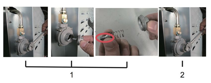
THANK YOU FOR YOUR PURCHASE

Thank you for your purchase! We know that you have many brands and products
to choose from and we are honored to know that you have decided to take one of
our products into your home and hope that you enjoy it.

COSMO appliances are designed according to the strictest safety and performance
standards for the North American market. We follow the most advanced
manufacturing philosophy. Each appliance leaves the factory after thorough quality
inspection and testing. Our distributors and our service partners are ready to answer
any questions you may have regarding how to install, use and care for your products.
We hope that this manual will help you learn to use the product in the safest and
most effective manner.

If you have any questions or concerns, please contact the dealer from whom you
purchased it, or contact our Customer Support Team at 1-888-784-3108, or visit
cosmoappliances.com.

Please read the important safety instructions before using the appliance for your
own safety, and to reduce the risk of hazards such as injury, fire and electrical shock.

Please keep this manual for future use.

Once again, thank you!

                                                                                           2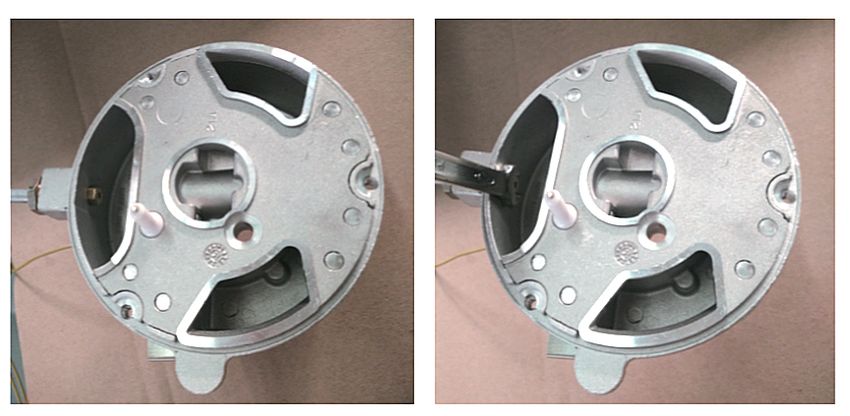
TABLE OF CONTENTS

    SAFETY & WARNINGS .......................................................... 4-5
    INSTALLATION INSTRUCTIONS ...........................................6-19
       Gas Connections ........................................................................6-7
       Installation / Clearances ..........................................................8-9
       Electrical Requirements ................................................................9
       Wiring Diagram ............................................................................10
       Cooktop Installation .....................................................................11
       Cutout Dimensions ........................................................................11
       Attaching the Cooktop ................................................................12
       Connecting Gas to Cooktop .................................................12-14
       Back Panel Rubber Pads .............................................................15
       Adjustable Leg Installation (48 in. Model) ...............................16
       Gas Conversion ........................................................................17-18
       Regulate Burner Flame Intensity ...............................................19
    PRODUCT DIAGRAMS .......................................................20-22
       COS-GRT304 ................................................................................20
       COS-GRT366 ..................................................................................21
       COS-GRT486G ..............................................................................22
    OPERATING INSTRUCTIONS .............................................23-25
       Guidelines for using Cooktop Burners .....................................23
       Surface Burner Ignition ...............................................................24
       Using the Griddle (48 in. Model) ...............................................24
       Tips for Using Pots & Pans ..........................................................25
       Burners & Recommended Pan/Pot Size ...................................25
       Wok Cooking .................................................................................25
    CARE & MAINTENANCE .....................................................26-27
       Cleaning the Cooktop .................................................................26
       Cleaning the Stainless Steel .......................................................26
       Cleaning the Burner Caps ..........................................................26
       Service & Maintenance ...............................................................26
       Greasing the Valves .....................................................................27
    TROUBLESHOOTING ..........................................................28-29
    WARRANTY & SERVICE .....................................................30-31

3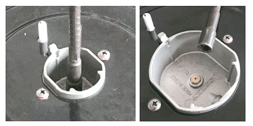
SAFETY & WARNINGS

• Read this entire installation manual            WARNING!: If the information in this
carefully prior to installation and save it   manual is not followed exactly as
for the local inspector’s reference. Keep     instructed, a fire or explosion may
this installation manual for future           result, causing property damage,
reference.                                    personal injury, or death.
• This installation must be completed by
a qualified appliance installer, service          IMPORTANT!
company, or gas supplier.                     • Installation and service must be
• Features and specifications are subject     performed by a qualified installer,
to change at any time without notice. If      service agency, or gas supplier.
you      have     any    questions,   visit   • Warranty service must be performed
cosmoappliances.com or call Cosmo             by a Cosmo Appliances authorized
Customer Service at: 1-888-784-3108.          service partner.
• The appliance must be installed in          • Do not store or use gasoline or other
accordance with National Electrical           flammable vapors and liquids in the
Codes, as well as all state, municipal        vicinity of this or any other appliance.
and local codes. The correct voltage,         • A ventilation hood is recommended
frequency, and amperage must be               for use with the Cosmo Gas Cooktop.
supplied to the appliance from a
                                              • In Massachusetts: Installations and
dedicated, grounded circuit breaker or
                                              repairs must be performed by a
time-delay fuse.
                                              qualified or licensed contractor,
• This Cosmo Gas Cooktop is                   plumber or gasfitter qualified or
manufactured for use with natural gas         licensed by the state, province, or
or liquid propane gas (LP) with an            region where this appliance is being
optional conversion kit, sold separately.     installed. Only use gas shut-off valves
                                              approved for use within the state,
To ensure the safe use of Cosmo               province, or region where this
appliances, please take note of the           appliance is being installed. A flexible
following    types   of     highlighted       gas connector, when used, must not
information throughout this guide:            exceed 3 feet (0.9 meters).

   •    IMPORTANT states important               WARNING!
   information    that    needs   your        WHAT TO DO IF YOU SMELL GAS:
   attention.                                 • DO NOT try to light any appliance.
   •    CAUTION indicates a situation         • DO NOT touch any electrical switch.
   where minor injury or product
                                              • DO NOT use any phone in your
   damage may occur if instructions
                                              building.
   are not followed.
                                              • Call your gas supplier immediately
   •    WARNING states a hazard that
                                              from a neighbor’s phone. Follow the
   may cause serious injury or death if
                                              instructions from the gas supplier for
   precautions are not followed.
                                              your own safety.
                                              • Call your local fire department if you
                                              cannot reach your gas supplier.

                                                                                         4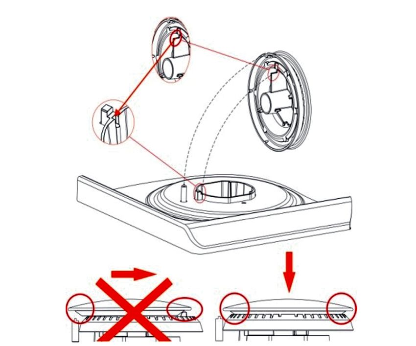
SAFETY & WARNINGS

        WARNING!                                • DO NOT TOUCH SURFACE BURNERS
    • Children should not play with             OR AREAS NEAR BURNERS. Surface
    packaging material. Dispose of the          burners may be hot after use, even
    carton and plastic bags after the range     though the flame is not visible or
    top is unpacked. Cartons covered with       contact the surface directly. Areas near
    rugs, bedspreads, or plastic sheets can     surface burners may become hot
    become air-tight chambers.                  enough to cause burns during and after
    • Remove all staples from the carton.       use.
    Staples can cause severe cuts and           • Do not let clothing or other flammable
    destroy finishes if they come in contact    materials contact with areas near
    with other appliances or furniture.         surface burners until they have had
    • Be safety conscious. The preparation      sufficient time to cool down.
    of food on a range top requires             • NEVER use this appliance as a space
    temperatures that could cause severe        heater to heat or warm the room.
    burns.                                      Doing so may result in carbon
    • Proposition 65: The California Safe       monoxide poisoning.
    Drinking Water and Toxic Enforcement
    Act of 1986 (Proposition 65) requires the   INSTALLATION & SAFETY
    Governor of California to publish a list    • Cosmo Gas Cooktop must be properly
    of substances known to the State of         installed and grounded by a qualified
    California     to   cause     cancer   or   technician in accordance with the
    reproductive harm.                          National Fuel Gas Code ANSI Z223.1-
    • Burning of gas can result in exposing a   latest edition, and the National
    low level of listed substances, including   Electrical Code ANSI/NFPA No.70-latest
    formaldehyde, benzene, soot, and            edition.
    carbon monoxide. This is caused             • Ask your dealer to recommend a
    primarily by the incomplete combustion      qualified technician and an authorized
    of natural gas or LP gas. Properly          repair service. Have the technician
    adjusted      burners    will    minimize   familiarize you with the locations of the
    incomplete combustion. Opening a            manual gas shut-off valve and gas
    window or using a ventilating range         meter in the event it is necessary to shut
    hood / fan can minimize exposure to         off the gas supply to the range top
    these substances.                           during an emergency.
    • DO NOT store any flammable                • DO NOT REPAIR OR REPLACE any
    materials near surface burners. The         part     of   the    appliance      unless
    type of materials includes paper,           specifically recommended by the
    plastic, and flammable liquids.             owner’s manual or customer service
    • DO NOT store explosives, such as          department. Repair service should be
    aerosol cans, on or near the range top      done      by    a      Cosmo-authorized
    • Failure to follow this owner’s manual     technician/service partner only. This
    could lead to serious injury or damage      will reduce the risk of personal injury
    to the product.                             and damage to the product.

5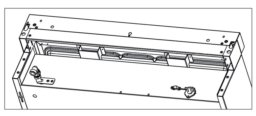
INSTALLATION INSTRUCTIONS

Be sure the cooktop is properly installed and grounded by a qualified technician. It is the
responsibility of the technician to make certain that your cooktop is properly installed.
Situations caused by the improper installation are not covered under the warranty. Any
expenses incurred due to such situations will not be paid by the manufacturer of the
cooktop. Leak testing of the appliance shall be conducted according to the manufacturer’s
instructions, or according to local building codes and gas regulations in your area.

GAS CONNECTIONS (All Units)

NOTICE TO MASSACHUSETTS APPLIANCE DEALERS: Be sure this document is included in all
gas cooktop appliances sold to consumers in the State of Massachusetts. Massachusetts
law requires the following:
   • Appliances must be installed by a licensed plumber or gas fitter.
   • Appliances must be connected with a three (3) foot (36” maximum length) flexible gas
   connector
   • A “T” handle type manual gas valve in the gas supply line to the appliance

Have the dealer where you purchase your new cooktop install it or have them recommend
a qualified installer. Installation must conform to local codes. In the absence of local codes,
the installation must conform with the National Fuel Gas Code, ANSI Z223.1-Latest Edition
in the U.S.A. or the CAN/CGA B149.1 or .2 Installation Codes in Canada.

The cooktop should be connected to the supply line with a 1/2 inch black iron pipe or a
certified flexible-type stove connector. To prevent gas leaks, put an approved sealing
compound that is resistant to liquefied petroleum gases on all threaded connections.

    IMPORTANT!: Do not apply pressure directly to the cooktop manifold pipe when
tightening supply connections. The manifold pipe should be held securely at the pressure
regulator to prevent twisting. Hold the pressure regulator with a wrench during the
tightening of the connection, or the manifold pipe may be twisted and split and cause a
dangerous leak.

The installation of cooktops designed for manufactured (mobile) home installation must
conform with the Manufactured Construction and Safety, Title 24 CFR, Part 3280, [formerly
the Federal standard for Mobile Home Construction and Safety, Title 24, HUD (Part 280)] in
the U.S.A. or C.S.A. Standard CAN/CGA Z240.4.2 in Canada or, when such standards are
not applicable, with local codes.
                                                               (Continued on next page)

                                                                                            6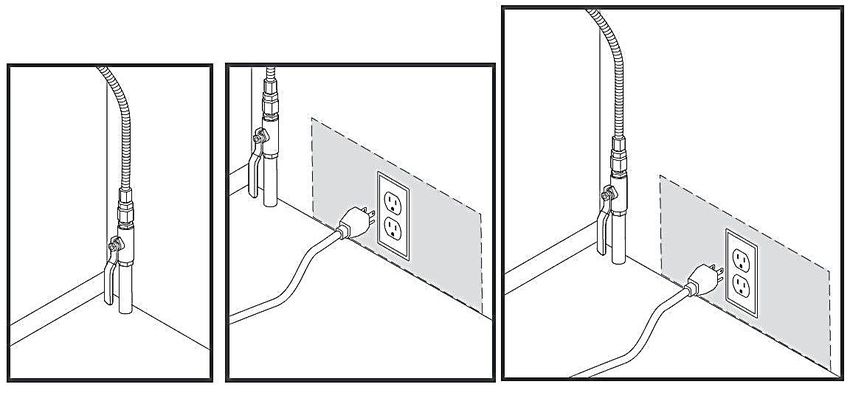
INSTALLATION INSTRUCTIONS

GAS CONNECTIONS (All Units) (Continued)
The installation of cooktops designed for recreational vehicle installation must
conform with state or other codes or, in the absence of such codes, with the
standard for recreational vehicles. ANSI A119.2.2–1982 in the U.S.A. or CAN/CGA
Z240.4.2 in Canada.

The installation of appliances designed for recreational park trailers must conform with
state or other codes or, in the absence of such codes, with the standard for recreational
park trailers, ANSI A119.5.

NOTE: Check all piping connections in the unit for leaks. Never use an open flame to check
for gas leaks. Use a soap solution, 75% water, 25% dishwashing soap. It is possible for
connections made at the factory to leak, due to vibration encountered in transportation.
Make certain you have checked them all, and repair any connections that leak.

The appliance and its individual shut-off valve must be disconnected from the gas supply
piping system during any pressure testing of that system at test pressures in excess of 1/2
PSIG. The appliance must be isolated from the gas supply piping system by closing its
individual manual shut-off valve during any pressure testing of the gas supply piping
system at test pressures equal to or less than 1/2 PSIG.

GAS LINE SHUT-OFF VALVE
• To reduce the possibility of gas leaks, apply Teflon tape or a thread compound approved
for use with LP or Natural gases to all threaded connections.
• Install a manual gas line shut-off valve in the gas line in an easily accessed location
outside the range in the gas piping external to the appliance for the purpose of turning on
or shutting off gas to the appliance.
• Install male 1/2’’(30 or 36-inch cooktop) or 3/4” (48-inch cooktop) flare union adapter to 1/
2” or 3/4’’ NPT internal thread elbow at the inlet of the regulator. Use a wrench on the
regulator fitting to avoid damage.
• Install male 1/2” or 3/4” flare union adapter to the NPT internal thread of the manual
shut-off valve, taking care to secure the shut-off valve to keep it from turning.
• Check for leaks using a leak detector or soapy water, 75% water, 25% dishwashing soap.

                                                                   (Continued on next page)

 7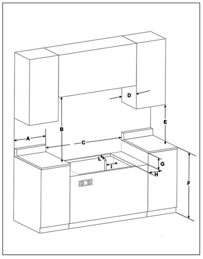
INSTALLATION INSTRUCTIONS

INSTALLATION / CLEARANCES
All units must be installed in accordance with the minimum rear and side wall clearances
and clearances extended vertically above the cooktop which are stated on the serial plate
(the serial plate is located on the back of the unit.)

Make sure that the wall coverings, countertops, and cabinets around the cooktop can
withstand temperatures of up to 200˚F / 93˚C generated by the cooktop. It is the
responsibility of the installer to make certain that the cooktop is properly adjusted at the
time of installation. Situations caused by improper adjustments or improper installation are
not covered under the warranty. Any expenses incurred due to such situations will not be
paid by the manufacturer of the appliance.

Installation without a range hood
• NOTE: All measurements are based on 24” (61 cm) deep cabinet
• This cooktop may be installed directly adjacent to existing 36” (91.4 cm) high base
cabinets.
• The cooktop CANNOT be installed directly adjacent to sidewalls, tall cabinets, tall
appliances, or other side vertical surfaces above 36” (91.4 cm) high. There must be a
minimum of 6” (15.2 cm) side clearance from the cooktop to such combustible surfaces
above the 36” (91.4 cm) counter height.
• Within the 6” (15.2 cm) side clearance to combustible vertical surfaces above 36” (91.4 cm),
the maximum wall cabinet depth must be 13” (33.0 cm) and wall cabinets within this 6” (15.2
cm) side clearance must be 18” (45.7 cm) above the 36” (91.4 cm) high countertop.
• Wall cabinets above the cooktop must be a minimum of 42” (106.7 cm) above the cooktop
cooking surface for the full width of the cooktop. This minimum height requirement does
not apply if a range hood is installed over the cooking surface.

   CAUTION!: Items of interest to children should not be placed in cabinets above the
cooktop. Children climbing on the cooktop to reach items could be seriously injured.

Installation with a range hood
• NOTE: Minimum clearance for the back wall is 0” with backsplash (backguard) or high
shelf.
• If a range hood is installed above the cooktop, maintain a 30” (76.2 cm) minimum
clearance between the cooktop and the bottom of the range hood.
• The range hood must exhaust outside.
• For best smoke elimination, the minimum clearance of the range hood should be installed
30” to 36” above the cooktop surface. Recommended CFM should be 600 CFM for the 30”
cooktop.
• Do not install with a downdraft ventilation system.
                                                               (Continued on next page)

                                                                                           8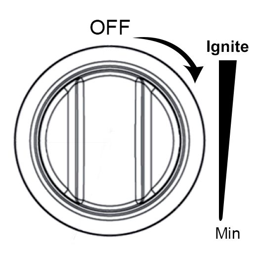
INSTALLATION INSTRUCTIONS

INSTALLATION / CLEARANCES (Continued)
Installation in an island
• NOTE: There must be a minimum of 6” (15.2 cm) clearance from the rear of the cooktop to
a combustible wall. Clearances from non-combustible materials are not part of the ANSI
Z21.1 scope and are not certified by CSA. Clearances to non-combustible materials must
be approved by the authority having jurisdiction.
• This cooktop may be installed directly adjacent to existing 36” (91.4 cm) high base
cabinets.
• The cooktop CANNOT be installed directly adjacent to sidewalls, tall cabinets, tall
appliances, or other side vertical surfaces above 36” (91.4 cm) high. There must be a
minimum of 6” (15.2 cm) side clearance from the cooktop to such combustible surfaces
above the 36” (91.4 cm) counter height.
• Within the 6” (15.2 cm) side clearance to combustible vertical surfaces above 36” (91.4
cm), the maximum wall cabinet depth must be 13” (33.0 cm) and wall cabinets within this
6” (15.2 cm) side clearance must be 18” (45.7 cm) above the 36” (91.4 cm) high countertop.
• Wall cabinets above the cooktop must be a minimum of 42” (106.7 cm) above the
cooktop cooking surface for the full width of the cooktop. This minimum height
requirement does not apply if a cooktop hood is installed over the cooking surface.

ELECTRICAL REQUIREMENTS
• Cosmo Gas Cooktop requires 110 volts, 50/60 Hz electrical supply to operate the ignition
system.
• The power cord is a 3-prong grounding plug. The plug must be plugged into a mating
outlet.
• Make sure there is a power outlet within the reach of the range top’s power supply cable
(within 36"/30cm from the right side of the range top). The outlet should be accessible
with the range top installed.
• Cooktop must be properly grounded for safe operation.
• DO NOT ground the cooktop to any of gas line/gas pipe.

9
INSTALLATION INSTRUCTIONS

ELECTRICAL REQUIREMENTS (continued)
Wiring Diagrams
   1.) Cable terminal
   2.) Ignition switch
   3.) Spark generator
   4.) Ignition spark L. Black N. White T. Green (earth)

                                                           10
INSTALLATION INSTRUCTIONS
COOKTOP INSTALLATION
• Installation and service must be performed by a qualified installer, service agency or the
gas supplier.
• Remove the cooktop from its package and set aside all burners, burner caps and cooking
grates.
• Gently slide in the range top half into the cut-out, make sure your gas connection and
electrical power plug are properly installed.
• Once this is done you’re now ready to slide the cooktop all the way back to the wall.
• Install all burners and burner caps
• Install all grates.
CUTOUT DIMENSIONS
A.) 6 in. / 152mm (min.)
B.) 30 in. min. -36 in. (max.)
C+.) 30 in. / 36 in. / 48 in. (Cutout)
C-.) 29.8 / 35.8 / 47.8 (Cooktop Size)
C+ D.) 13 in. / 330mm (max.)
E.) 18 in. / 457mm
F.) 36 in. / 914mm
G.) 6.5 in. / 165mm
H.) 1 in. / 25mm (min.)
I.) 0.56 in. / 18mm
L.) 2 in. / 51mm (min.)
11INSTALLATION INSTRUCTIONS
ATTACHING THE COOKTOP
To prevent liquids from leaking accidentally into the underlying storage space,
the appliance is equipped with a special gasket. To apply this gasket:
1.) Lay out the protective sealing strips along the edges of the opening in the countertop
and carefully overlap the strip end.
2.) Insert the cooktop into the countertop opening.
3.) With a screwdriver, assemble brackets to the cooktop bottom with the screws
(See below diagram).
4.) Slide the hooks into position and secure them with the screws.
5.) Trim the part of the sealing strips which extend beyond the hotplate base.
CONNECTING GAS TO COOKTOP
Before installing the cooktop consider the location of the gas supply and routing the gas
line.
• This cooktop is designed to operate at a pressure of 4” of the water column on natural
gas or 10” of the water column on propane gas (LPG).
• This cooktop can be converted for use with Liquid Propane gas (LPG). When using this
cooktop with LPG gas, the conversion must be made by a qualified installer before
attempting to operate the cooktop with that gas. LP kit can be purchased from an
authorized Cosmo dealer or contact Cosmo Customer Service for further assistance.
Continued on next page
12INSTALLATION INSTRUCTIONS
CONNECTING TO GAS COOKTOP (continued)
• For correct operation, the pressure of natural gas supplied to the regulator should be
between 4” and 5” of the water column. For LP gas, the pressure supplied must be between
10” and 12” of the water column.
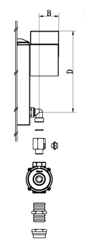
• For NG: The gas supply is connected to the regulator
loose. The inlet connection has a 1/2" B.S.P. male
thread. IT IS ESSENTIAL THAT THE ELBOW ON THE
APPLIANCE BE HELD FIRMLY WITH A SPANNER
WHEN CONNECTING THE SUPPLY. DO NOT OVER
B = 1.89 in. TIGHTEN. The regulated pressure for NG is 4” W.C.
D = 7.91 in.
(See diagram).
• For LPG: The gas supply is connected to the regulator
loose. The inlet connection has a 1/ 2" B.S.P. male
thread. IT IS ESSENTIAL THAT THE ELBOW ON THE
APPLIANCE BE HELD FIRMLY WITH A SPANNER WHEN
CONNECTING THE SUPPLY. DO NOT OVER TIGHTEN.
The regulated pressure For LPG is 10” w.c. (See
diagram).
• When checking for the correct operation of the regulator, the inlet pressure must be at
least 1” more than the operating manifold pressure as given above.
• The pressure regulator located at the inlet of the cooktop manifold must remain in the
supply line regardless of Natural (NG) or Liquid Propane (LP) gas is being used.
• A flexible metal appliance connector used to connect the cooktop to the gas supply
should be 3 feet/91.4 cm max. in length for easy installation. In Canada, flexible connectors
should be single-wall metal connectors less than 6 feet / 182.9 cm in length.
• Shut off the main gas supply valve before removing the old cooking appliance (if
applicable) and leave it off until the new hook-up has been completed. Don’t forget to
relight the pilots on other gas appliances when you turn the gas back on.
• Because hard piping restricts the movement of the cooktop, the use of a CSA-certified
flexible metal appliance connector is recommended unless local codes require a hard-
piped connection. Never reuse an old connector when installing a new cooktop. If the hard
piping method is used, you must carefully align the pipe.
Continued on next page
13INSTALLATION INSTRUCTIONS
CONNECTING TO GAS COOKTOP (continued)
To prevent gas leaks, use pipe joint compound resistant to NG gases on all-male external
pipe threads.
1.) In an easily accessible location, install a service manual gas shut-off valve. Be sure
everyone operating the cooktop knows where and how to shut off the gas supply to the
cooktop.
2.) Use a flexible gas line to connect to the 1/2” fitting, located on the bottom right-
hand corner underneath the cooktop. For gas inlet position, refer to diagrams below.
B = 1.89 in.
D = 7.91 in.
A = 3.01 in.
B = 2.56 in.
E = 5.37 in.
F = 4.05 in.
3.) When all connections have been made, be sure all cooktop controls are in the OFF
position and turn on the main gas supply valve. Check for gas leaks by using a 75%
water, 25% dishwashing soap solution. If a gas leak is present, shut off the gas
immediately, tighten all connections, and retest for leaks.
NOTE: Any opening in the wall behind the appliance and in the floor under the appliance
shall be sealed.
14INSTALLATION INSTRUCTIONS
Rubber Pad Installation on Back Panel
To prevent the cooktop from coming into contact with the wall, 2 rubber pads are
included with the cooktop. To install the pads to the back panel of the cooktop:
1.) Locate the installation kit packed with the appliance.
勹勹
Screws (2x) Rubber Pad (2x)
2.) Install the 2 rubber pads on the back of the cooktop as shown:
15INSTALLATION INSTRUCTIONS
Adjustable Leg Installation (48 in. Model Only)
The 48 inch cooktop may include adjustable feet. To install the adjustable feet to the
bottom of the cooktop:
1.) Locate the installation kit packed with the appliance.
2.) Arrange the cooktop on the floor with soft material for protection. Set aside all the
cooking grates, burners, and griddle cover to avoid any potential damage.
3.) Lift up the front side of the cooktop, and install the front three legs; the legs are
installed by turning counterclockwise.
4.) Lay down the cooktop back on the floor, then lift the backside to install the back
three legs; the legs are installed by turning counterclockwise.
16INSTALLATION INSTRUCTIONS
NATURAL GAS (NG) TO LIQUEFIED PETROLEUM (LP) GAS CONVERSION
INSTALLATION AND SERVICING MUST BE PERFORMED BY A QUALIFIED INSTALLER. SAVE THIS
MANUAL FOR THE LOCAL INSPECTOR’S USE. READ AND SAVE THESE INSTRUCTIONS FOR FUTURE
REFERENCE.
WARNING!: This conversion kit must be installed by a qualified service technician in
accordance with the manufacturer's instructions and all applicable codes and requirements of the
authority having jurisdiction. Failure to follow instructions may result in fire, explosion or
production of carbon monoxide causing property damage, personal injury or loss of life. The
qualified service agency is responsible for the proper installation of this kit. The installation is not
proper and complete until the operation of the converted appliance is checked as specified in the
manufacturer's instructions supplied with this kit.
WARNING!: Before proceeding with the conversion, shut off the gas supply before
disconnecting electrical power to the range. Be sure power supplies are off before installing the
conversion kit. Failure to do so could cause serious bodily injury.
Determine the combination of top burners that are featured on your cooktop. Identify the parts
you need from this kit to complete the LP conversion. To order the LP Conversion Kit for your
cooktop model, please visit cosmoappliances.com.
Changing the Burner Nozzles Burner BTU & Orifice Sizes (From NG to LP)
Lift up the burners and unscrew the nozzles
using an adjustable 7mm wrench, then replace COS-GRT304
with nozzles designed for the gas supply you are
converting to. Left Front, 18,000 BTU: 1.08 mm
Left Rear, 4,200 BTU: 0.65 mm
IMPORTANT!: Save the nozzles/orifices Right Front, 13,000 BTU: 0.90 mm
removed from the cooktop for future use.
Right Rear, 8,500 BTU: 0.83 mm
COS-GRT366
Left Front, 18,000 BTU: 1.08 mm
Left Rear, 13,000 BTU: 0.90 mm
Mid Front, 8,500 BTU: 0.83 mm
Mid Rear, 8,500 BTU: 0.83 mm
Right Front, 13,000 BTU: 0.90 mm
Right Rear, 4,200 BTU: 0.65 mm
COS-GRT486G
Left Front, 12,000 BTU: 1.0 mm
Left Rear, 12,000 BTU: 1.0 mm
Griddle, 15,000 BTU: 1.16 mm
Mid Front, 18,000 BTU: 1.22 mm / 1.24 mm
Mid Rear, 12,000 BTU: 1.0 mm
Right Front, 12,000 BTU: 1.0 mm
Right Rear, 12,000 BTU: 1.0 mm
17INSTALLATION INSTRUCTIONS
NATURAL GAS (NG) TO LIQUEFIED PETROLEUM (LP) GAS CONVERSION (Continued)
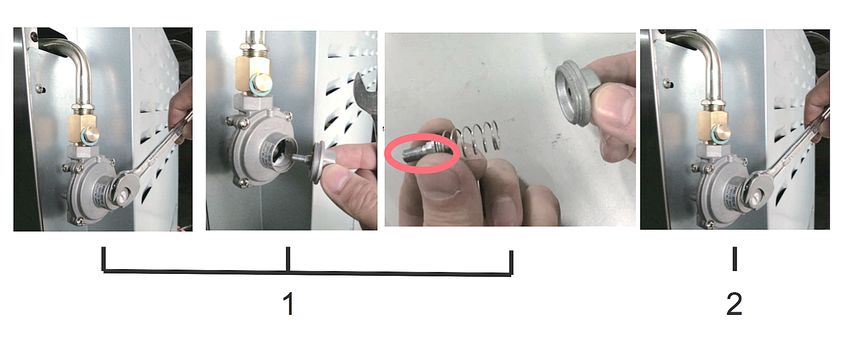
Pressure Regulator Adjustment for Gas Conversion
The pressure regulator supplied with the cooktop is a convertible pressure regulator for use
with Natural Gas (NG) at a nominal outlet pressure of 4” W.C., or Liquefied Petroleum Gas
(LP) at a nominal outlet pressure of 10” W.C.
Your cooktop is shipped from the factory set for
B = 1.89 in. use with NG. It can be converted for use with LP
D = 7.91 in. by following steps below.
(NOTE: The agency performing this work assumes
responsibility for the conversion.)
1.) Unscrew, by hand, the upper metal stopper of
the regulator.
2.) Unscrew, by hand, the white plastic piece
screwed under the above-mentioned metal
stopper. Next, screw back in the white plastic piece
in the OPPOSITE way under the metal stopper (For
gas reference, see the written “LP” and “NAT” with
relative indicating arrows on the white piece).
3.) Screw back in, by hand, the metal stopper in
the original position on the regulator.
18INSTALLATION INSTRUCTIONS
REGULATE BURNER FLAME INTENSITY
To regulate the minimum flame on the burners, carry out the following procedure
indicated below:
1.) Turn on the burner and put the knob onto position MINIMUM (small flame).
2.) Remove the knob of the tap which is set for standard pressure. The knob is
found on the shaft of the valve itself.
3.) Besides the valve shaft, use a small screwdriver that fits the gold-colored screw
found on the lower part of the tap and turn the adjustment clock-wise or counter
clock-wise until the minimum flame reaches the desired intensity level.
4.) Make sure that that the flame does not go out when changing the position quickly
from MAXIMUM to the MINIMUM position. If it does, the minimum flame intensity
needs to be increased.
19PRODUCT DIAGRAM - GRT304
1.3 in.
7.87 in.
27.
37
in.
SIDE VIEW
29.87 in.
1.3 in.
7.87 in.
FRONT VIEW
2.75 in.
23.9 in.
27.37 in.
TOP VIEW
20PRODUCT DIAGRAM - GRT366
TOP VIEW
36"
36"
8.7" FRONT VIEW
27" 0.8"
24"
6.9" SIDE VIEW
25.8"
27.4"
21PRODUCT DIAGRAM - GRT486G
TOP VIEW
47.9"
47.9"
8.7" FRONT VIEW
27" 0.8"
24"
6.9" SIDE VIEW
25.8"
27.4"
22OPERATING INSTRUCTIONS
GUIDELINES FOR USING COOKTOP BURNERS
WARNING!: Keep cooktop area clear and free from combustible materials, gasoline,
and other flammable vapors and liquid.
WARNING!: DO NOT use the cooktop as a room/space heater; this may result in
carbon monoxide poisoning.
• This appliance is intended for cooking food; it must NOT be used for any other purpose.
• Never leave the range top unattended when in use. Boil over causes smoking and
greasy spills that may ignite.
• Never allow flames to extend beyond cookware or curl up its sides. This could discolor
and damage the utensil and you may get burned by a hot handle.
• Keep handles out of the way. Turn handle so that they don’t extend over the edge of the
range or another burner that is on.
• Use caution when deep-frying. Oil or fat can overheat very quickly, particularly on a high
setting.
• Make sure that all burner parts are properly in place and ensure burner caps are installed
correctly. Incorrectly or incompletely assembled burners may produce dangerous flames.
See "Care & Maintenance", Page 26.
• Keep the burners clean. Especially after a spill or boil over, make sure you clean the
affected burners before using them again. Food residue may clog the igniter and the
notches of the flame spreader, stopping the burner from functioning correctly. See "Care &
Maintenance" on Page 26.
• Check that the burner flames are regular. They should be blue with no yellow tipping and
burn without fluttering all around the burner cap. For burner troubleshooting, see Page 28.
• DO NOT store dangerous or flammable material in the cabinet areas above the cooktop.
• DO NOT use aerosol sprays in the vicinity of the cooktop while it's operating.
• DO NOT use unstable or deformed cookware to avoid safety hazards, such as spillovers.
• Always ensure that the knobs are in the "OFF" position when the cooktop is not in use.
• The cooktop must be regularly cleaned and maintained for safe use; see Page 26.
• Before maintenance and cleaning, disconnect the appliance from power and allow it to
cool completely.
• Ensure that air can circulate around the gas cooktop; poor ventilation can result in a lack
of oxygen and extinguish the flame.
• The cooktop produces heat and humidity in the room where it is installed.
• There are dual burners that have the same low turn-down setting (SIM) for gentle
simmering (620 BTU/hour). Use the SIM setting for melting chocolate and butter, cooking
rice and delicate sauces, simmering soups and stews, and keeping cooked food hot.
• Ensure the room where the cooktop is installed is well-ventilated. Keep adequate natural
ventilation or install a range hood with a discharge tube.
• Supply the cooktop with the type of gas stamped on the relevant label situated in the
immediate vicinity of the gas connection tube.
23OPERATING INSTRUCTIONS
SURFACE BURNER IGNITION
Light the burners before placing pans on the grid
and check that the flame is regular.
1.) Push and turn the appropriate control knob
counter-clockwise to the “IGNITE” position;
you will hear a clicking noise the sound of the
electric spark igniting the burner.
2.) Once burner ignition has been achieved,
then turn the burner control knob to adjust the
desired heat setting (See diagram). Reduce the
flame size by turning the knob counter-
clockwise to your desired flame height.
If the burner does not light, turn the knob to
its original position and try again. Always lower
the flame or turn it off before removing the pan.
NOTE: When first used, the gas burner will not ignite immediately. Hold the
knob pressed down for an extended time for the gases to fully fill the operating system.
NOTE: When one burner is turned to the “HI” position, the burner igniters will spark.
Do not attempt to disassemble or clean around any burner while another burner is
on. Do not touch any burner cap, burner base, or igniter while the igniters are sparking.
GRIDDLE IGNITION (FOR 48 IN. MODELS ONLY)
Before using the Griddle
1.) Clean the griddle thoroughly with warm, soapy water to remove dust or protective
coating. Rinse with clean water and wipe off to dry with a soft, clean, lint-free cloth.
2.) Remove the stainless steel griddle cover before turning the griddle on.
3.) Make sure the grease tray is under the front edge of the griddle; position the tray under
the griddle overhang to catch grease or food residue.
Using the Griddle
1.) Push and turn the control knob counter-clockwise to the preferred cooking temperature.
2.) Preheat the griddle for approximately 10-12 minutes.
3.) When the griddle is preheated to the desired temperature, the indicator light will turn
on.
4.) Place the food on the griddle to cook.
TIP: Butter or cooking oil can be added for more flavor.
CAUTION!: The griddle surface will be hot after use; allow it to cool before cleaning.
24OPERATING INSTRUCTIONS
TIPS FOR USING POTS & PANS CORRECTLY
Always ensure that the bottom and handles of pots and pans do not over-
extend from the cooktop. When cooking with flammable fat such as oil, do not
leave the range unattended. Use pots of the appropriate size on each burner
using the following chart:
BURNER & RECOMMENED POT/PAN SIZE
• Auxiliary: 3 1/2 - 5 1/2 in. (90 - 140mm)
• Semi Rapid: 5 1/2 - 10 1/4 in. (140 - 260mm)
• Rapid: 7 1/8 - 10 1/4 in. (180 - 260mm)
• Dual Burner: 8 2/3 - 10 1/4 in. (220 - 260mm)
When boiling liquids, turn the knob to the MINIMUM position once boiling is
reached to avoid overflow. Always use pots with a matching lid. Dry the bottom of
cookware before cooking. Use pots with a flat, thick bottom (except for wok cooking).
WOK COOKING
Always use the wok adapter supplied with the range. Wok pan external diameter shall
not be smaller than 10" (25cm) and larger than 16" (40cm).
WARNING!: DO NOT use an open flame when checking for leaks.
25CARE & MAINTENANCE
CLEANING THE COOKTOP
Periodically clean the burner heads, the cast iron grates, and the burner caps using warm
water. Remove burned food and fat residue with a rubber spatula. If food residue
prevents the smooth operation of the knob controls, please contact Cosmo Customer
Service to schedule service by a factory-trained professional (See Page 29).
CLEANING THE STAINLESS STEEL
For best results, use a stainless steel cleaning product with a soft sponge or
wipe. Alternatively, use a soft sponge or cloth with a warm soap and water solution.
Never use abrasive powders or liquids.
CLEANING THE BURNER CAPS
Lift the burner caps from the burner
heads and wash them with soap and
warm water. Dry thoroughly before use.
Before reinstalling them on the burner
head, check that the gas flow holes are not
clogged with food or cleaning product
residue.
See diagram to properly install the burner
caps.
SERVICE & MAINTENANCE
Service and maintenance must carried out by authorized professionals only. To replace
parts such as burners, valves, and electric components, the cooktop must be removed from
the countertop by releasing the attachment hooks, loosening the attachment screws of
each burner, unscrewing the cooktop attachment nuts which are visible at the bottom of
the surface, removing the cooktop stainless steel top, and finally replacing the defective
parts.
NOTE: If the valves must be replaced, first disassemble the ignition switches wires. It is
recommended to replace the valve gaskets each time the valve is replaced, ensuring a
perfect seal between the body and the gas manifold.
WARNING!: Disconnect power before servicing unit.
WARNING!: After the initial installation of the appliance or after any service concerning
main gas parts of the appliance, perform a leak test using water with soap on the gas
connections in order to verify proper installation (See Page 14). Do not use fire/open
flames to test for gas leaks.
26CARE & MAINTENANCE
GREASING THE VALVES
If it becomes difficult to operate the valve, it should be greased immediately by following
the steps below:
1.) Disassemble the valve body by loosening the two screws located on the body of the
valve.
2.) Extract and clean the seal cone and its housing with a rag soaked with thinners.
3.) Lightly grease the cone with special grease.
4.) Insert the cone, moving it several times, remove it again, remove the excess grease
and make sure that the gas passageways are unobstructed.
5.) Replace all the pieces in reverse order and check that the valve operates correctly.
27TROUBLESHOOTING
PROBLEM POSSIBLE CAUSE SOLUTION
Burners will not Burner parts or igniters may Check burner parts are clean,
light be wet, dirty or misaligned dry and correctly assembled.
Check igniters are clean and
dry; see Page 26
Top burner will not Failed thermocouple Replace thermocouple
stay lit
Flames do not burn Burner parts may be dirty or See "Care & Maintenance",
all around the misaligned Page 26
burner cap
Burner flames are • Burner bezel ports are • Clean burner bezel ring ports
very large and clogged. Burner ports or with straightened paper clip,
burner caps are not needle, or wire
yellow
positioned properly
• Remove and carefully re-
• Range top is being operated install burner bezel and caps
with the wrong type of gas
• Ensure that the type of range
• Regulator is not Installed, is top matches the gas supply
faulty, or is set for the wrong
type of gas • Check installation, replace
regulator, or set regulator for
proper gas
Igniters are Gas shut-off valve is in the Turn shut-off valve to the “ON”
sparking but “OFF” position position
burners are not
igniting
Burner flame goes • Low gas pressure • Contact gas company
out at low setting
• Air intake holes around • Remove obstruction from air
burners are obstructed intake holes
The flames have A draft or spill has Turn the burners off, cleaning
suddenly gone out extinguished the flame the burners and the sump area.
Once clean, reignite top
burners
28TROUBLESHOOTING
PROBLEM POSSIBLE CAUSE SOLUTION
No ignition spark Dead batteries or ignition Replace batteries and
module failed attempt ignition; if there is still
no spark ignition, the range
top burners can still be used.
To light them:
1.) Holding a lit match to
the flame spreader, push in
on the control knob and turn
counter clockwise to LIGHT
2.) When the flame is burning
all the way around the
burner, you may adjust the
heat
"Cracking" or This is the sound of metal This is normal, no action is
"popping" sound is heating and cooling necessary
heard coming from
cooktop
29WARRANTY AND SERVICE
For full warranty details on this product please visit:
http://www.cosmoappliances.com/warranty
TO RECEIVE WARRANTY SERVICE, YOUR
PRODUCT MUST BE REGISTERED. TO REGISTER, VISIT:
WWW.COSMOAPPLIANCES.COM/WARRANTY
SCAN TO REGISTER
30IMPORTANT
Do Not Return This Product To The Store If
you have a problem with this product, please contact
Cosmo Customer Support at
+1(888)784-3108
DATED PROOF OF PURCHASE, MODEL #, AND SERIAL #
REQUIRED FOR WARRANTY SERVICE
IMPORTANT
Ne pas Réexpédier ce Produit au Magasin
Pour tout problème concernant ce produit, veuillez contacter
le service des consommateurs Cosmo Customer Support au
+1(888) 784-3108
UNE PREUVE D’ACHAT DATEE EST REQUISE POUR BENEFICIER DE
LA GARANTIE.
IMPORTANTE
No regrese este producto a la tienda
Si tiene algún problema con este producto, por favor contacte el
AYUDA AL CLIENTE COSMO al
+1(888)784-3108
(Válido solo en E.U.A).
NECESITA UNA PRUEBA DE DE COMPRA FECHADA, NÚMERO DE
MODELO Y DE SERIE PARA EL SERVICIO DE LA GARANTÍA
Correct Disposal of this product:
This marking indicates that this appliance should not
be disposed with other household wastes. To prevent
possible harm to the environment or human health
from uncontrolled waste disposal, recycle it responsibly to
promote the sustainable reuse of material resources.
31Cosmo is constantly making efforts to improve the quality and
performance of our products, so we may make changes to our
appliances without updating this manual.
Electronic version of this manual is available at:
www.cosmoappliances.comYou can also read