Rotational axis RA-40 - Assembly and operating instructions - Translation of the Original Assembly Instructions EN - Afag
←
→
Page content transcription
If your browser does not render page correctly, please read the page content below
Assembly and operating instructions
Rotational axis
RA-40
Translation of the Original Assembly Instructions EN
RA-40-2F
RA-40-4F
Assembly instructions EN RA-40-2F - RA-40-4F Date 06.09.2021 Version 2.0 1–56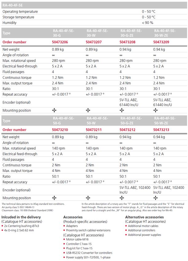
Dear Customer
Thank you for choosing our products and placing your trust and confidence in
our company!
These assembly and operating instructions contain all essential information you
need about your product. Our aim is to provide the required information as
concisely and clearly as possible. If, however, you still have any questions on
the contents or suggestions, please do not hesitate to contact us. We are always
grateful for any feedback.
Our team will also be glad to answer any further question you may have
regarding the rotational axis or other options.
We wish you every success with our products!
With kind regards
Your Afag team
© Subject to modifications
The rotational axes have been designed by Afag according to the state of the
art. Due to the constant technical development and improvement of our
products, we reserve the right to make technical changes at any time.
Updates of our documentations
Unlike the printed documents, our digital instructions manuals, product data
sheets and catalogues are being continuously updated on our website.
Please keep in mind that the digital documents on our website are always the
latest versions.
© Copyright 2021 Afag Engineering GmbH
All contents of the present assembly and operating instructions, in particular the
texts, photographs and graphics, are protected by copyright. All rights reserved.
No part of these assembly and operating instructions may be reproduced,
distributed (made available to third parties), or transmitted in any form or by any
means, including photocopying, recording, or other electronic or mechanical
methods, without the prior written permission of Afag.
Afag Engineering GmbH
Gewerbestraße 11
DE-78739 Hardt (Germany)
Tel.: +49 7422 560 030
e-mail: sales@afag.com
Internet: www.afag.com
2 – 56 Assembly instructions EN RA-40-2F - RA-40-4F Date 06.09.2021 Version 2.0
Table of contents
Table of contents
1 General .................................................................................................................... 6
1.1 Contents and purpose of these assembly instructions................................. 6
1.2 Explanation of symbols................................................................................. 6
1.3 Additional symbols........................................................................................ 7
1.4 Applicable documents .................................................................................. 8
1.5 Warranty ....................................................................................................... 8
1.6 Liability .......................................................................................................... 8
2 Safety instructions ................................................................................................. 9
2.1 General ......................................................................................................... 9
2.2 Intended use ................................................................................................. 9
2.3 Foreseeable misuse ..................................................................................... 9
2.4 Obligations of the operator and the personnel ........................................... 10
2.4.1 Observe the assembly instructions ...................................................... 10
2.4.2 Obligations of the operating company.................................................. 10
2.4.3 Obligations of the personnel ................................................................ 11
2.5 Personnel requirements ............................................................................. 11
2.5.1 Personnel qualification ......................................................................... 11
2.6 Personal protective equipment (PPE) ........................................................ 12
2.7 Changes and modifications ........................................................................ 12
2.8 General hazards / residual risks ................................................................. 13
2.8.1 General hazards at the workplace ....................................................... 13
2.8.2 Danger due to electricity ...................................................................... 14
2.8.3 Danger due to strong magnetic fields. ................................................. 14
2.8.4 Danger due to high temperatures ........................................................ 14
2.8.5 Mechanical hazards ............................................................................. 15
3 Technical data ...................................................................................................... 16
3.1 Rotational axis RA-40-2F ........................................................................... 16
3.1.1 Dimensional drawing RA-40-2F ........................................................... 16
3.1.2 Technical data RA-40-2F ..................................................................... 17
3.1.3 Dimensional drawing RA-40-2F-5E...................................................... 18
3.1.4 Technical data RA-40-2F-5F ................................................................ 19
3.2 Rotational axis RA-40-4F ........................................................................... 20
3.2.1 Dimensional drawing RA-40-4F ........................................................... 20
3.2.2 Technical data RA-40-4F ..................................................................... 21
3.2.3 Dimensional drawing RA-40-4F-5E...................................................... 22
3.2.4 Technical data RA-40-4F-5F ................................................................ 23
3.3 Module stresses ......................................................................................... 24
4 Transport, packaging and storage ..................................................................... 25
4.1 Safety instructions for transport.................................................................. 25
4.2 Scope of supply .......................................................................................... 25
Assembly instructions EN RA-40-2F - RA-40-4F Date 06.09.2021 Version 2.0 3–56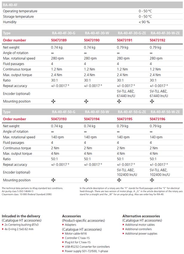
Table of contents
4.3 Transport .................................................................................................... 26
4.4 Packaging ................................................................................................... 26
4.5 Storage ....................................................................................................... 26
5 Design and description ....................................................................................... 27
5.1 Structure rotational axis .............................................................................. 27
5.2 Product description ..................................................................................... 27
6 Installation, assembly and setting ..................................................................... 28
6.1 Safety instructions for installation and assembly ....................................... 28
6.2 Assembly and attachment .......................................................................... 28
6.2.1 Mounting material ................................................................................. 28
6.2.2 Tightening torques................................................................................ 29
6.3 Connection ................................................................................................. 30
6.3.1 Power supplies ..................................................................................... 30
6.3.2 Servo controller .................................................................................... 31
6.3.3 Axis controller C11x0 ........................................................................... 32
6.3.4 Axis controller C12x0 ........................................................................... 34
6.3.5 Axis controller E12x0............................................................................ 36
6.3.6 Motor connector ................................................................................... 38
6.4 Pin assignment (encoder)........................................................................... 39
6.4.1 Round plug on the module .................................................................. 39
6.4.2 SUB-D connector on the controller ...................................................... 39
6.4.3 Electrical feedthrough/initiator cable extension R11 ............................ 40
6.4.4 Y-distribution connector R12 ................................................................ 40
6.4.5 Reference sensor ................................................................................. 40
6.5 Programming .............................................................................................. 41
6.6 Settings ....................................................................................................... 41
6.6.1 Speed electric axes .............................................................................. 41
6.6.2 Switching distance - reference sensor for electric axes ....................... 42
7 Commissioning .................................................................................................... 43
7.1 Safety instructions for commissioning ........................................................ 43
7.2 Commissioning of the modules .................................................................. 43
8 Fault elimination................................................................................................... 44
8.1 Safety instructions for troubleshooting ....................................................... 44
8.2 Fault causes and remedy ........................................................................... 44
9 Maintenance and repair ....................................................................................... 45
9.1 General notes ............................................................................................. 45
9.2 Safety instructions for maintenance and repair .......................................... 45
9.3 Maintenance activities and maintenance intervals ..................................... 45
9.3.1 Overview of the maintenance points .................................................... 46
9.3.2 Lubrication ............................................................................................ 46
9.3.3 Further maintenance ............................................................................ 46
9.4 Spare parts lists .......................................................................................... 47
4 – 56 Assembly instructions EN RA-40-2F - RA-40-4F Date 06.09.2021 Version 2.0
Table of contents
9.4.1 Servo controller .................................................................................... 47
9.4.2 Encoder ................................................................................................ 47
9.4.3 Overview motor cable (axis controller application) .............................. 48
9.4.4 Motor cable........................................................................................... 49
9.5 Repair and overhaul ................................................................................... 50
10 Decommissioning, disassembly, disposal ........................................................ 51
10.1 Safety instructions for decommissioning and disposal............................... 51
10.2 Decommissioning ....................................................................................... 51
10.3 Disposal ...................................................................................................... 51
11 Declaration of incorporation ............................................................................... 52
Assembly instructions EN RA-40-2F - RA-40-4F Date 06.09.2021 Version 2.0 5–56
General
1 General
1.1 Contents and purpose of these assembly instructions
These assembly instructions contain important information on assembly,
commissioning, functioning and maintenance of the rotational axis RA-40 to
ensure safe and efficient handling and operation.
Consistent compliance with these assembly instructions will ensure:
permanent operational reliability of the rotational axis,
optimal functioning of the rotational axis,
timely detection and elimination of defects (thereby reducing maintenance
and repair costs)
Prolonging of the rotational axis service life.
The illustrations in this manual shall provide you with a basic understanding of
the module and may vary from the actual design of your module.
1.2 Explanation of symbols
The safety notes are marked by a pictogram and a signal word. The safety notes
describe the extent of the hazard.
DANGER
Danger!
This safety note indicates an imminently hazardous situation which, if not
avoided, will result in death or serious injury.
WARNING
Warning!
This safety note points out a potentially hazardous situation which, if not
avoided, could result in death or serious injury.
CAUTION
Caution!
This safety note points out a potentially dangerous situation which, if not
avoided, can result in minor or slight injuries.
NOTICE
This safety note points out a potentially dangerous situation which, if not
avoided, can cause substantial damage to property and the environment.
6 – 56 Assembly instructions EN RA-40-2F - RA-40-4F Date 06.09.2021 Version 2.0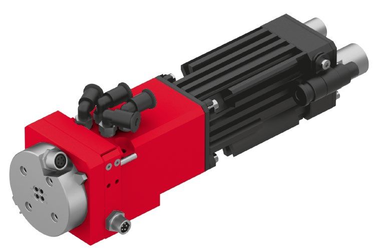
General
This note contains important additional information as well as useful tips for
safe, efficient and trouble-free operation of the rotational axis.
Further warning signs:
Where applicable, the following standardised symbols are used in this manual
to point out the various potential health risks.
Warning - Dangerous electrical voltage.
Warning - Risk of injury from contact with hot surfaces.
Warning - Risk of hand and finger injury due to uncontrolled
movements of components.
Warning - Magnetic field
Warning - back injury due to heavy lifting.
Warning - Risk of injury as a result of parts being flung out!
Warning -high noise levels
1.3 Additional symbols
In these assembly instructions the following symbols are used to highlight
instructions, results, references, etc.
Symbol Description
1. Instructions (steps ...)
Results of actions
References to sections
Enumerations not ordered
Assembly instructions EN RA-40-2F - RA-40-4F Date 06.09.2021 Version 2.0 7–56
General
1.4 Applicable documents
Each rotational axis is accompanied by a safety information sheet. This
information sheet must be read carefully by every person who carries out work
on and with the rotational axis.
1.5 Warranty
The warranty terms for Afag handling components and handling systems are
the following:
24 months from initial operation and up to a maximum of 27 months from
delivery.
Wear parts are excluded from the warranty (The customer is entitled to a
product free of defects. This does also apply to defective accessories and
wear parts. Normal wear and tear are excluded from the warranty.
The warranty covers the replacement or repair of defective Afag parts. Further
claims are excluded.
The warranty shall expire in the following cases:
Improper use of the module.
Non-observance of the instructions regarding assembly, commissioning,
operation and maintenance of the module.
Improper assembly, commissioning, operation and maintenance.
Repairs and design changes carried out without prior technical instructions
of Afag.
Removing the serial number from the product.
Inadequate checking of wear parts.
Non-observance of the EC Machinery Directive, the Accident Prevention
Regulations, the Standards of the German Electrotechnology Association
(VDE) and these safety and assembly instructions.
1.6 Liability
No changes shall be made to the rotational axis unless described in this
instructions manual or approved in writing by Afag.
Afag accepts no liability for unauthorized changes or improper assembly,
installation, commissioning, operation, maintenance or repair work.
8 – 56 Assembly instructions EN RA-40-2F - RA-40-4F Date 06.09.2021 Version 2.0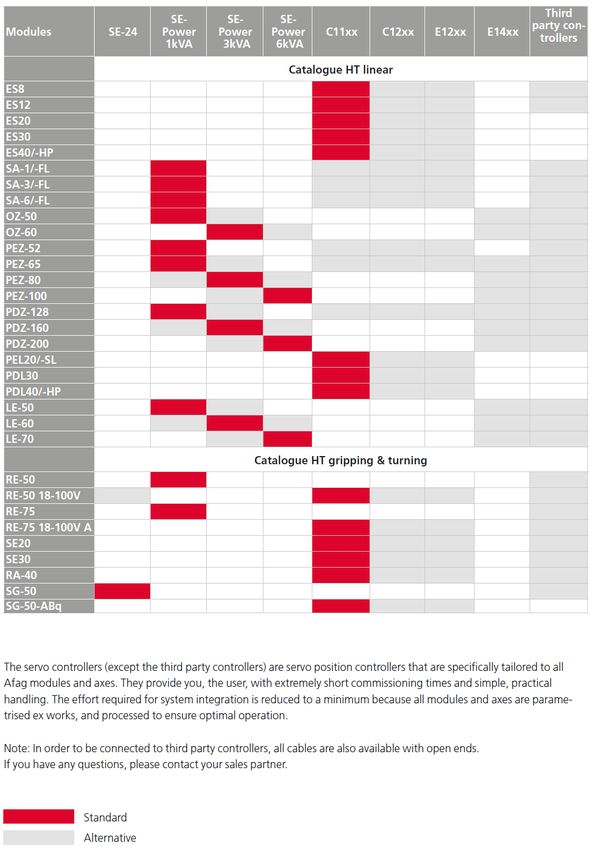
Safety instructions
2 Safety instructions
2.1 General
This chapter provides an overview of all important safety aspects to ensure safe
and proper use of the rotational axis and optimal protection of personnel.
Safe handling and trouble-free operation of the module requires knowledge of
the basic safety regulations.
Every person carrying out installation, commissioning, maintenance work or
operating the module must have read and understood the complete user
manual, especially the chapter on safety instructions.
Beyond this, there are rules and regulations regarding accident prevention that
are applicable to the place of installation which must be observed.
Improper use may result in danger to life and limb of the user or third parties or
in damage to the automation system or other material assets.
Failure to follow the directions and safety instructions given in this instructions
manual may result in serious hazards.
2.2 Intended use
The rotary axes are used in automation systems and are used to move
workpieces in non-hazardous environments and in the ambient and operating
conditions defined for these modules (Chapter 3 Technical data).
The rotational axes are designed exclusively for gripping payloads that do not
pose any danger to persons, property, or the environment during manipulation.
In combination with other modules the modules can be used as a pick & place
station.
Any use beyond the described purpose is not in accordance with the intended
use.
The intended use of the module also includes:
observance of all instructions given in this instructions manual.
compliance with the inspection and maintenance work and the
specifications in the data sheets,
using only original spare parts.
2.3 Foreseeable misuse
Any use other than or beyond the intended use described above is considered
a misuse of the rotational axis.
Especially the following use is considered a misuse:
Use in potentially explosive atmospheres
Assembly instructions EN RA-40-2F - RA-40-4F Date 06.09.2021 Version 2.0 9–56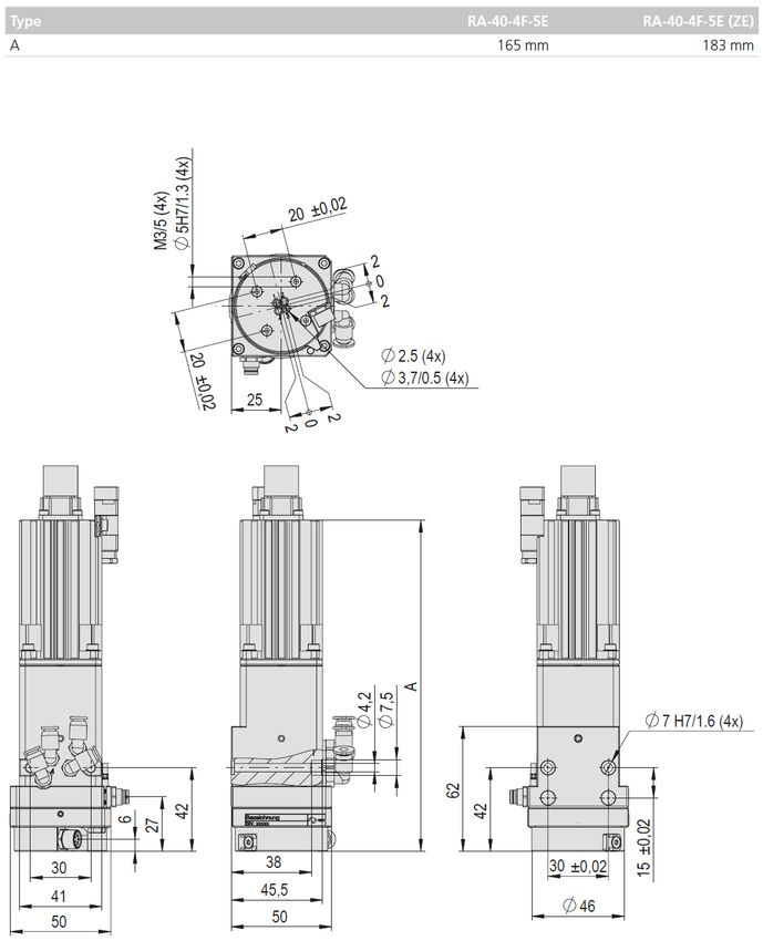
Safety instructions
WARNING
Risk of injury if the module is not used as intended!
The improper use of the rotational axis poses a potential hazard to the
personnel.
The rotational axes may only be used in a technically perfect condition in
accordance with its intended use and the instructions in this manual as well
as in compliance with the safety requirements!
Any malfunctions, particularly those that could impair safety, must be
eliminated immediately!
Risks can occur if the module is not used as intended. In the event of
damages caused by improper use the following shall apply:
the operating company shall be solely responsible for such damage, and
Afag does not accept any liability for damage caused by improper use.
2.4 Obligations of the operator and the personnel
2.4.1 Observe the assembly instructions
A basic prerequisite for safe and proper handling of the rotational axis is a good
knowledge of the basic safety instructions.
These assembly instructions, in particular the safety instructions contained
therein, must be observed by all persons working with the rotational axis.
2.4.2 Obligations of the operating company
In addition to the safety instructions given in this manual, the operating company
must comply with the safety, accident prevention and environmental protection
regulations valid for the field of application of the rotational axis.
The operating company is required to use only personnel who:
have the necessary professional qualifications and experience,
are familiar with the basic rules regarding occupational safety and accident
prevention,
have been instructed in the correct handling of the rotational axis,
have read and understood these assembly instructions.
The operating company is also required to:
monitor on an ongoing basis that the personnel work safely considering any
potential hazard involved and the assembly instructions are observed,
ensure that the assembly instructions are always kept at hand at the
installation in which the modules are mounted,
observe and communicate universally applicable laws and regulations
regarding accident prevention and environmental protection,
provide the necessary personal protective equipment (e.g., protective
gloves) and instruct the personnel to wear it.
10 – 56 Assembly instructions EN RA-40-2F - RA-40-4F Date 06.09.2021 Version 2.0Safety instructions
2.4.3 Obligations of the personnel
All personnel working with the modules are required to:
read and observe these assembly instructions, especially the chapter on
safety,
observe the occupational safety and accident prevention regulations,
observe all safety and warning signs on the rotational axis,
refrain from any activity that might compromise safety and health.
In addition, the personnel must wear the personal protective equipment
required for carrying out their work. (Chapter 2.6).
2.5 Personnel requirements
2.5.1 Personnel qualification
The activities described in the assembly instructions require specific requisites
at the level of professional qualifications of the personnel.
Personnel not having the required qualification will not be able to asses the risks
that may arise from the use of the rotational axis thus exposing himself and
others to the risk of serious injury. Therefore, only qualified personnel may be
permitted to carry out the described activities on the rotational axis.
Persons whose ability to react is restricted due to the intake of medication or the
like must not interact with the rotational axis.
These installation instructions are intended for skilled personnel (installers,
system integrators, maintenance personnel, technicians), electricians and
operating personnel.
The following is a description of the professional skills (qualifications) required
for carrying out the different activities:
Qualified personnel:
Qualified personnel with appropriate training who are qualified due to their
special know-how and fully familiar with the machine and who have been given
instructions on how to carry out the task entrusted to them safely.
Qualified electrician:
Persons who have obtained their electrical qualifications through appropriate
professional training and complementary courses that enables them to identify
risks and prevent possible hazards resulting from electricity.
Operator (trained personnel):
Authorized persons who due to their specialized professional training,
expertise and experience are capable of identifying risks and preventing
possible hazards arising from the use of the machine.
Assembly instructions EN RA-40-2F - RA-40-4F Date 06.09.2021 Version 2.0 11–56Safety instructions
2.6 Personal protective equipment (PPE)
The personal protective equipment serves to protect the personnel from hazards
affecting their safety and health at work.
When working on/with the rotational axis, the personnel must wear the personal
protective equipment assigned by the safety officer of the operating company or
as required by safety regulations. In addition, the personnel is required to:
wear the personal protective equipment provided by the operating company
(employer),
check the personal protective equipment for proper condition, and
immediately notify the person responsible on site of any defects found on the
personal protective equipment.
Personal protective equipment and the respective mandatory signs:
Protective clothing is a close-fitting clothing specifically
designed to protect personnel from hazards during work.
Protective gloves are specifically designed to protect the
personnel against hand injuries (such as cuts, abrasion,
burns).
Safety shoes are specifically designed to protect the
personnel against foot injuries from crushing, falling objects or
slipping on slippery surfaces.
Hearing protectors are required to protect the personnel
against excessive noise levels to prevent noise-induced
hearing loss.
2.7 Changes and modifications
No changes may be made to the rotational axis which have not been described
in these assembly instructions or approved in writing by Afag.
Afag accepts no liability for unauthorised changes or improper assembly,
installation, commissioning, maintenance or repair work.
The rotational axis may not be changed or modified in any way, except with
the prior written consent of Afag.
12 – 56 Assembly instructions EN RA-40-2F - RA-40-4F Date 06.09.2021 Version 2.0Safety instructions
2.8 General hazards / residual risks
Despite the safe design of the rotational axis and the technical protective
measures taken, there still remain residual risks that cannot be avoided, and
which present a non-obvious residual risk when operating the module.
Observe the safety instructions in this chapter and in the other sections of this
manual to avoid damage to property and dangerous situations for the personnel.
2.8.1 General hazards at the workplace
The rotational axis has been built according to the state-of-the-art and the
applicable health and safety requirements. However, improper use of the
rotational axis may cause the following hazards to the personnel:
danger to life and limb of the operator or third parties,
on the rotational axes themselves,
property damage.
Always keep the assembly instructions ready at hand at the workplace!
Furthermore, the following apply:
the general and local regulations on accident prevention and environmental
protection,
the safety information sheet for the rotational axis.
WARNING
Danger - Do not use in unsuitable environment!
The rotational axes are designed for use in non explosive atmospheres.
Do not use the modules in potentially explosive atmospheres!
WARNING
Risk of injuries due to uncontrolled parts movements!
When connecting and operating the rotational axes, unexpected movements
can lead to serious injuries and/or damage to property.
Only qualified personnel may work with or on the rotational axis.
CAUTION
Risk of injury due to high noise exposure!
The noise level of the rotational axis at full load operation is below 78 dB(A).
Depending on the add-ons, the environment and the resonance of the
protective device theses values may be exceeded and expose the operator
to a higher noise level.
The operating company is responsible for ensuring that the permissible
noise levels are observed.
Assembly instructions EN RA-40-2F - RA-40-4F Date 06.09.2021 Version 2.0 13–56Safety instructions
CAUTION
Risk of injury from being caught!
Rotative movements of the module can catch pieces of clothing, hair or
materials and injure people.
Maintenance and care should only be carried out by qualified personnel.
Wear personal protective equipment!
2.8.2 Danger due to electricity
DANGER
Danger! Risk of electric shock!
If work on electrical components is required, ensure that the work is carried
out properly, failure to do so will cause serious or fatal injuries.
Work on the machine's electrical equipment may only be performed by
skilled electrician or trained personnel under the supervision of a skilled
electrician in accordance with all relevant electrical regulations.
Only work on electrical systems when they are de-energised!
2.8.3 Danger due to strong magnetic fields.
DANGER
Danger due to strong magnetic fields.
Due to the strong magnetic fields, electronic devices such as pacemakers
can be disturbed or their function impaired.
Persons with a pacemaker must keep a safety distance of at least 0.2 [m]
cm.
The system must be provided with appropriate warning signs.
The personnel shall be instructed accordingly
2.8.4 Danger due to high temperatures
CAUTION
Danger of injury from hot surfaces.
During operation, maintenance and repair of the rotational axis, the surface
heats up to 60°C.
Wear protective gloves!
Before touching hot surfaces without protective gloves, make sure they
have cooled down to ambient temperature.
14 – 56 Assembly instructions EN RA-40-2F - RA-40-4F Date 06.09.2021 Version 2.0Safety instructions
2.8.5 Mechanical hazards
CAUTION
Danger of injury by moving components!
Limbs can be injured by moving components (bruises, contusions, broken
bones)!
Work on and with the rotational axis may only be carried out by qualified
personnel.
Never reach into the system during normal operation!
Provide suitable protective enclosure.
Assembly instructions EN RA-40-2F - RA-40-4F Date 06.09.2021 Version 2.0 15–56Technical data
3 Technical data
3.1 Rotational axis RA-40-2F
3.1.1 Dimensional drawing RA-40-2F
Fig. 1 Dimensional drawing rotational axis RA-40-2F
16 – 56 Assembly instructions EN RA-40-2F - RA-40-4F Date 06.09.2021 Version 2.0Technical data
3.1.2 Technical data RA-40-2F
Assembly instructions EN RA-40-2F - RA-40-4F Date 06.09.2021 Version 2.0 17–56Technical data
3.1.3 Dimensional drawing RA-40-2F-5E
Fig. 2 Dimensional drawing rotational axis RA-40-2F-5F
18 – 56 Assembly instructions EN RA-40-2F - RA-40-4F Date 06.09.2021 Version 2.0Technical data
3.1.4 Technical data RA-40-2F-5F
Assembly instructions EN RA-40-2F - RA-40-4F Date 06.09.2021 Version 2.0 19–56Technical data
3.2 Rotational axis RA-40-4F
3.2.1 Dimensional drawing RA-40-4F
Fig. 3 Dimensional drawing rotational axis RA-40-4F
20 – 56 Assembly instructions EN RA-40-2F - RA-40-4F Date 06.09.2021 Version 2.0Technical data
3.2.2 Technical data RA-40-4F
Assembly instructions EN RA-40-2F - RA-40-4F Date 06.09.2021 Version 2.0 21–56Technical data
3.2.3 Dimensional drawing RA-40-4F-5E
Fig. 4 Dimensional drawing rotational axis RA-40-4F-5F
22 – 56 Assembly instructions EN RA-40-2F - RA-40-4F Date 06.09.2021 Version 2.0Technical data
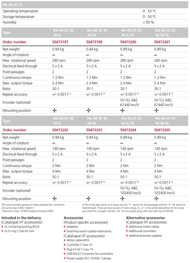
3.2.4 Technical data RA-40-4F-5F
Assembly instructions EN RA-40-2F - RA-40-4F Date 06.09.2021 Version 2.0 23–56Technical data
3.3 Module stresses
24 – 56 Assembly instructions EN RA-40-2F - RA-40-4F Date 06.09.2021 Version 2.0Transport, packaging and storage
4 Transport, packaging and storage
4.1 Safety instructions for transport
CAUTION
Risk of injury when unpacking the rotational axis!
The rotational axes are packed in the original packaging (cardboard box). If
handled incorrectly, the module may fall out of the box when unpacked and
cause limb injuries.
Carefully unpack the rotational axes.
Also observe the safety instructions in chapter 2 „Safety instructions“ in
this manual.
4.2 Scope of supply
In addition to the assembly and operating instructions, a safety information
sheet is enclosed with each rotational axis.
This information sheet must be read by every person who carries out work
with and on the rotational axis!
Fig. 5 Scope of delivery rotational axis
[Unt] RA-40
1x Rotational axis RA-40
2x Centering bushing ø 7x3 mm
4x O-Ring 2.5x0.62 mm
1x Assembly & operating instructions
Assembly instructions EN RA-40-2F - RA-40-4F Date 06.09.2021 Version 2.0 25–56Transport, packaging and storage
4.3 Transport
No liability can be assumed for damages caused by improper installation on
the part of the operating company.
The following conditions must be complied with for transport and storage:
Storage temperature: 0-50 °C
Relative air humidity: < 90%, non condensing
4.4 Packaging
The rotational axis is transported in the Afag transport packaging. If no Afag
packaging is used, the rotational axis must be packed in such a way that it is
protected against shocks and dust.
The packaging materials used are mainly cardboard and paper or PE film.
NOTICE
Risk to the environment due to incorrect disposal of the packaging
material
Environmental damage can be caused by incorrect disposal of the packaging
material.
Dispose of the packaging material in an environmentally sensitive way in
accordance with the local environmental regulations ( chapter 10.3).
4.5 Storage
If the rotational axis is stored for an extended period, observe the following:
Store the rotational axis in the transport packaging.
Do not store the rotational axis outdoors or expose it to weather conditions.
The storage space must be dry and dust free.
Room temperature of the storage space: 0-50 °C.
Relative air humidity: < 90% non condensing.
Clean the rotational axis and protect the blank metal parts against corrosion
using the appropriate means.
Protect the rotational axis from dirt and dust.
26 – 56 Assembly instructions EN RA-40-2F - RA-40-4F Date 06.09.2021 Version 2.0Design and description
5 Design and description
5.1 Structure rotational axis
1
Fig. 6 Dimensional drawing rotational axis RA-40-4F
5.2 Product description
The rotational axis RA is a precision-engineered, highly compact electric axis
for rotating payloads.
Further technical information can be found in the chapter 3 Technical data in
these installation instructions.
Assembly instructions EN RA-40-2F - RA-40-4F Date 06.09.2021 Version 2.0 27–56Installation, assembly and setting
6 Installation, assembly and setting
The rotational axis is an incomplete machine. For safe operation, the module
must be integrated into the safety concept of the system in which it is installed.
During normal operation, it must be ensured that the user cannot interfere with
the working area of the rotational axis. This can be achieved through suitable
protective measures (e.g., enclosure, light grid).
When the system is running in special operating modes, it must be ensured that
there is no danger to the operator.
NOTICE
Risk of damage due to incorrect installation!
Incorrect installation can damage the module RA-40.
Only use original LinMot cables for the connection.
Mount the rotational axis only up to an outer dimension of max. 600 mm
above the end plates.
Recommendation to achieve higher accuracy: Fix the axle with fixing blocks
(approx. every 100 mm).
The system operator is responsible for the installation of the rotational axis in
a system! No warranty will be granted for damage caused by improper
installation on the part of the operating company.
6.1 Safety instructions for installation and assembly
Also observe the safety instructions in chapter 2 „Safety instructions“ in this
manual.
6.2 Assembly and attachment
6.2.1 Mounting material
The accessories depend on the rotational axis used as well as the adapter
and weight.
Module Recommended mounting material
RA-40 2/4x O-ring 2.5x0.62 NBR70
2x Ø7x3 mm centering bushing
2x Ø5x2.5 mm centering bushing
Fig. 7 Accessories (mounting material)
28 – 56 Assembly instructions EN RA-40-2F - RA-40-4F Date 06.09.2021 Version 2.0Installation, assembly and setting
6.2.2 Tightening torques
For assembling use screws with the following minimum specifications:
Standard VDI 2230
Screw strength Category 8.8
Surface: Galvanized blue, oiled or greased
Thread Tightening torque
M3 1.1 … 1.4 Nm
M4 2.6 … 3.3 Nm
M5 5.2 … 6.5 Nm
M6 9.0 … 11.3 Nm
M8 21.6 … 27.3 Nm
Assembly instructions EN RA-40-2F - RA-40-4F Date 06.09.2021 Version 2.0 29–56Installation, assembly and setting
6.3 Connection
6.3.1 Power supplies
The following is an overview of the technical data of the power supply units. For
further information on installation, please refer to the respective operating
instructions for the power supply unit.
Fig. 8 Overview of power supply units
Technical data SPH500-7207 SPH1013-7214 NT01-72/1500Multi
Type primary switched power primary switched power primary switched power
supply supply supply
Primary voltage 90-132VAC, 50/60Hz or 3x340 – 550 VAC, 50/60 3x230/400/480 VAC,
180-264VAC, 50/60Hz
Hz 50/60 Hz
(automatic switching)
Secondary voltage 54-80 VDC adjustable 54-80 VDC adjustable DC 72 V
Output power 480 W 960 W 1140 W
Peak output current (>0.5 s) 10 A 27 A 50 A
Efficiency 88% 91.5% 85% (at nominal power)
Protect. class IP 20 IP 20 IPXXB
Operating temperature -25…70 °C -25…70 °C 0…40 °C
Ground 1 kg 2 kg 19 kg
Dimension (HxWxD) 125x62x121mm 230x66x177mm 275x280x165mm
External fuse 6 A (C, D, K type) 16-32 A (C, D, K Type) 6 A (C, D, K type)
30 – 56 Assembly instructions EN RA-40-2F - RA-40-4F Date 06.09.2021 Version 2.0Installation, assembly and setting
6.3.2 Servo controller
Fig. 9 Overview servo controller
Assembly instructions EN RA-40-2F - RA-40-4F Date 06.09.2021 Version 2.0 31–56Installation, assembly and setting
6.3.3 Axis controller C11x0
The following is an overview of the controller's interfaces. For more information
on the C11x0 controller, please refer to the data sheet.
The controllers are pre-configured so that, as a rule, no software adjustments
are necessary. If adjustments are to be made, the software "LinMot-Talk" can
be obtained free of charge from the website"www.linmot.com".
32 – 56 Assembly instructions EN RA-40-2F - RA-40-4F Date 06.09.2021 Version 2.0Installation, assembly and setting
Net
72V
DC
Safety Relays
PWR+ PGND
RS232
Net
24V
DC
GND +24VD Motor
Quickstop
Ext.
Measuring
2x RT Ethernet system
Fig. 10 Axis controller C11x0
Connection Description
X1 PWR+ Motor power supply +72VDC
X1 PGND Motor power supply GND
X2 Motor phases
X3 Motor Signals
X33 Safety relay (optional for -S1 version)
X4.8 Quickstop
X4.7 Reference sensor (optional)
X4.2 Logic power supply 24VDC
X4.1 Logic voltage supply GND
DANGER
Danger from electric shock when the safety door is open!
Work on the electrical system carried out unprofessionally can cause serious
or fatal injuries.
Safely disconnect the power supply unit (72V) on the primary side at the
controller C11x0 or switch off the input "Safety Relay" (X33).
Assembly instructions EN RA-40-2F - RA-40-4F Date 06.09.2021 Version 2.0 33–56Installation, assembly and setting
6.3.4 Axis controller C12x0
The following is an overview of the controller's interfaces. For more information
on the C12x0 controller, please refer to the data sheet.
The controllers are pre-configured so that, as a rule, no software adjustments
are necessary. If adjustments are to be made, the software "LinMot-Talk" can
be obtained free of charge from the website"www.linmot.com".
34 – 56 Assembly instructions EN RA-40-2F - RA-40-4F Date 06.09.2021 Version 2.0Installation, assembly and setting
Net
72V
DC
Safety Relays
PWR+ PGND
RS232
Net
24V
DC
Motor cable
GND +24VD
RT Ethernet
RT Ethernet Ext.
/Quick Measuring
system
Fig. 11 Axis controller C12x0
Connection Description
X1 PWR+ Motor power supply +72VDC
X1 PGND Motor power supply GND
X2 Motor phases
X3 Motor Signals
X33 Safety relay (optional for -S1 version)
X4.8 Quickstop
X4.7 Reference sensor (optional)
X4.2 Logic power supply 24VDC
X4.1 Logic voltage supply GND
DANGER
Danger from electric shock when the safety door is open!
Work on the electrical system carried out unprofessionally can cause serious
or fatal injuries.
Safely disconnect the power supply unit (72V) on the primary side at the
controller C11x0 or switch off the input "Safety Relay" (X33).
Assembly instructions EN RA-40-2F - RA-40-4F Date 06.09.2021 Version 2.0 35–56Installation, assembly and setting
6.3.5 Axis controller E12x0
The following is an overview of the controller's interfaces. For more information
on the E12x0 controller, please refer to the data sheet.
The controllers are pre-configured so that, as a rule, no software adjustments
are necessary. If adjustments are to be made, the software "LinMot-Talk 1100"
can be obtained free of charge from the website"www.linmot.com".
Technical data E1230-DP-UC E1250-DP-UC E1250-PL-UC E1250-SE-UC
Logistics supply 24V DC 24V DC 24V DC 24V DC
Motor power supply 24…80V DC 24…80V DC 24…80V DC 24…80V DC
Max. motor output current (at Standard version: 32 Standard version Standard version Standard version
72 V) A 32 A 32 A 32 A
Bus systems Interfaces Profibus, CANopen, EtherCat, PowerLink, Sercos over Ether-
DeviceNet, CANopen, CANopen, cat, CANopen,
RS485/232m, Digital DeviceNet, DeviceNet, DeviceNet,
I/Os, Master RS485/232, Digital RS485/232, Digital RS485/232, Digital
Encoder I/Os, Master I/Os, Master I/Os, Master
Encoder Encoder Encoder
Max. power consumption 30 W 30 W 30 W 30 W
Protect. class IP 20 IP 20 IP 20 IP 20
Operating temperature 0…40 °C 0…40 °C 0…40 °C 0…40 °C
Ground 1.5 kg 1.5 kg 1.5 kg 1.5 kg
Distance between controllers 20mm left/right 20mm left/right 20mm left/right 20mm left/right
50mm bottom/top 50mm bottom/top 50mm bottom/top 50mm bottom/top
Fuse protection 72 V supply 20 AT 20 AT 20 AT 20 AT
Fuse protection 24 V supply 2 AT 2 AT 2 AT 2 AT
Technical data E1250-IP-UC E1250-PN-UC C1250-SC-UC
Logistics supply 24V DC 24V DC 24V DC
Motor power supply 24…80V DC 24…80V DC 24…80V DC
Max. motor output current (at Standard version: 32 A Standard version 32 A Standard version 32 A
72 V)
Bus systems Interfaces Ethernet IP, CANopen, Profinet, CANopen, Sercos III, CANopen,
DeviceNet, RS485/232, DeviceNet, RS485/232, DeviceNet, RS485/232,
Digital I/Os, Master Digital I/Os, Master Encoder Digital I/Os, Master
Encoder Encoder
Max. power consumption 30 W 30 W 30 W
Protect. class IP 20 IP 20 IP 20
Operating temperature 0…40 °C 0…40 °C 0…40 °C
Ground 1.5 kg 1.5 kg 1.5 kg
Distance between controllers 20 mm left/right 20 mm left/right 20 mm left/right
50 mm bottom/top 50 mm bottom/top 50 mm bottom/top
Fuse protection 72 V supply 20 AT 20 AT 20 AT
Fuse protection 24 V supply 2 AT 2 AT 2 AT
36 – 56 Assembly instructions EN RA-40-2F - RA-40-4F Date 06.09.2021 Version 2.0Installation, assembly and setting
Net
72V
DC
PGND PWR+
Net
24V
DC
ID-Setting
of controller in
hex GND +24VD
RS232
Ethernet
Ext. Motor
Measuring
system
Master (optional)
Encoder Quickstop
Profibus DP RT Ethernet Out Safety voltage
enable
(E1130DP CANopen RT Ethernet In
only) RS485 Analogue
In
Fig. 12 Axis controller E12x0
Connection Description
X1 PWR+ Motor power supply +72VDC
X1 PGND Motor power supply GND
X2 Motor phases
X3 Motor Signals
X4.12 Safety voltage enable
X4.11 Quickstop
X4.7 Reference sensor (optional)
X14.2 Logic power supply 24VDC
X14.1 Logic voltage supply GND
DANGER
Danger from electric shock when the safety door is open!
Work on the electrical system carried out unprofessionally can cause serious
or fatal injuries.
Safely disconnect the power supply unit (72V) on the primary side at the
E12x0 controller.
Assembly instructions EN RA-40-2F - RA-40-4F Date 06.09.2021 Version 2.0 37–56Installation, assembly and setting
6.3.6 Motor connector
Combination (connector on axle) Combination (connector on controller)
R connector: D connector:
Insert: Insert:
- Electric slide ES20 - Controller E11x0 Standard
- Portal axis PEL20
- Rotational axis SE20
C connector: W connector:
Insert: Insert:
- Electric slide ES30 - Controller E11x0 Standard, HC and XC
- Portal axis PEL30 - Controller E12x0 UC
- Portal axis PDL30
- Portal axis PDL40
- Portal axis PDL40-HP
- Rotational axis SE30
Y-Stecker:
Einsatz:
- Regler C11x0 XC
- Regler C1210 XC
38 – 56 Assembly instructions EN RA-40-2F - RA-40-4F Date 06.09.2021 Version 2.0Installation, assembly and setting
6.4 Pin assignment (encoder)
6.4.1 Round plug on the module
Cable connector S713 12-pole M12x1 PIN Function Colour
1 Free -
2 Z+ Grey 10
3 Z- Grey 9
4 Free -
5 +5V Grey 2
6 A- Grey 5
7 A+ Grey 6
8 B- Grey 7
9 B+ Grey 8
10 Free -
11 Free -
12 GND Grey 3
Housing Screen outer screen
NC Red 1
NC Grey 4
6.4.2 SUB-D connector on the controller
PIN Function Colour
1 +5V Pink
2 A- / sin- Yellow
3 B- / cos- Grey
4 Z- / data - White
5 GND Red/blue+violet
Controller C11xxx 6 Free -
7 Free -
8 Clock- Green
9 A+ / sin+ Black
10 B+ / cos+ Red
11 Z+ / Data+ Blue
12 Free -
13 Free -
14 Free -
15 Clock+ Grey/pink
Housing Screen Outer screen
Assembly instructions EN RA-40-2F - RA-40-4F Date 06.09.2021 Version 2.0 39–56Installation, assembly and setting
6.4.3 Electrical feedthrough/initiator cable extension R11
Socket 5-pin M8x1
PIN Colour
1 Brown
2 White
3 Blue
4 Black
5 Grey
Connector 5-pole M8x1
Housing Outer screen
6.4.4 Y-distribution connector R12
PIN on C PIN on A PIN on B Function Colour
1 1 1 24VDC Brown
2 4 - Signal A White
3 3 3 GND Blue
4 - 4 Signal B Black
5 - - NC Grey
Housing Outer
screen
6.4.5 Reference sensor
Connector 3-pole M8x1e PIN on A Function Colour
1 24VDC Brown
2 Signal White
3 GND Blue
40 – 56 Assembly instructions EN RA-40-2F - RA-40-4F Date 06.09.2021 Version 2.0Installation, assembly and setting
6.5 Programming
CAUTION
Risk of injuries due to uncontrolled parts movements!
Incorrect programming can cause the rotational axis to make rapid or
uncontrolled movements or to drive into the stop without braking and cause
serious injuries or damage to property.
Ensure that the enclosure is closed and that there are no persons or loose
parts/objects in the working area.
Have programming carried out by qualified personnel only.
Programming is done differently depending on the controller used. Observe
the respective manuals of the controller manufacturers!
6.6 Settings
6.6.1 Speed electric axes
The speeds of the electric axes are usually specified by the higher-level control
system. Sample programmes are available for various control systems. This
allows the maximum speed, acceleration and target position to be set. The
programmes are supplied on a CD or are available on the following page:
https://www.afag.com/de/service/support-tools/linmot.html.
When using the B1100-PP or E1100-GP controller with EasyStep firmware,
these travel profiles are stored in the controller.
NOTICE
Risk of property damage in case of excessive speed/acceleration
Excessive speed or acceleration can cause damage to the unit or peripherals.
Observe the reference values (speed, acceleration, deceleration) in the
following tables.
DANGER
Danger! Risk of electric shock!
Work on the electrical system carried out unprofessionally can cause serious
or fatal injuries.
With the C1xx0 controller, the safety inputs X33 must be safely
disconnected, or the power supply unit (72 V) must be disconnected on the
primary side!
The standard parameters may not meet the requirements of your application.
The parameters depend on the load mass and the mechanical structure of
the system.
Assembly instructions EN RA-40-2F - RA-40-4F Date 06.09.2021 Version 2.0 41–56Installation, assembly and setting
First, the drive must be referenced. The options listed below are then available.
Possibility 1: Manual shifting
Move axes manually into position (logic voltage ON, power motors OFF) and
then read values from the controller for transfer to the Pick&Place movement.
Possibility 2: Jog mode
Add or subtract value to the current position.
Can be programmed via relative command. The existing module for absolute
positioning can be converted into a module for relative positioning by
changing a variable.
Possibility 3: Set up with safely reduced speed
Please observe the associated instructions for safely reduced speed.
Max. Max. Max. Std. Std. Std. Max. Max.
Type speed Accel. Delay Speed Accel. Delay Item Item
[m/s] [m/s2] [m/s2] [m/s] [m/s2] [m/s2] [mm] [mm]
RA-40-x-50-x 0.84 30 30 0.84 20 20 - -
RA-40-x-30-x 1.7 20 20 1.7 15 15 - -
6.6.2 Switching distance - reference sensor for electric axes
The reference sensor of the rotational axes is mounted with a feeler gauge at
a distance of 0.1 mm parallel to the switching lug. The positions can be found
in the respective drawings (note the axle types).
42 – 56 Assembly instructions EN RA-40-2F - RA-40-4F Date 06.09.2021 Version 2.0Commissioning
7 Commissioning
After connection, the rotational axes are put into operation for the first time via
the system controller.
Only commission the rotational axes with attachments and superstructures in
setup or jog mode!
7.1 Safety instructions for commissioning
WARNING
Risk of injuries due to uncontrolled parts movements!
Incorrect programming can trigger uncontrolled movements of the rotational
axis and cause serious or fatal injuries and material damage.
Make sure that there are no persons or tools in the working area of the
rotational axis.
CAUTION
Risk of injury due to mounted components!
Attachments can be a risk in conjunction with moving parts.
Take appropriate measures to ensure safe operation!
Also observe the safety instructions in chapter 2 „Safety instructions“ in this
manual.
Please also observe the installation instructions for the control unit used!
7.2 Commissioning of the modules
Proceed carefully and follow the instructions step by step when commissioning
the modules for the first time:
1. Switch off the control and use a lockout device to make sure that the control
cannot be started up again.
2. Connect the encoder cable.
3. Connect the motor cable.
4. Connect the reference switch cable.
5. Switch on the controller unit and check the correct function of the encoder
and the reference switch.
6. Perform test run:
- Start with slow movements
- Subsequently under normal operating conditions
Commissioning is completed.
Assembly instructions EN RA-40-2F - RA-40-4F Date 06.09.2021 Version 2.0 43–56Fault elimination
8 Fault elimination
8.1 Safety instructions for troubleshooting
WARNING
Danger of injury due to faulty troubleshooting!
Poorly performed troubleshooting work can lead to serious injuries and
damage to property.
Only use trained specialist personnel for troubleshooting.
All work on the modules must be carried out with the power supply cut off!
WARNING
Risk of injuries due to uncontrolled parts movements!
Signals from the control system can trigger unintentional movements of the
rotational axis, which can cause injury.
Switch off the control unit before starting work on the module.
Observe the operating instructions of the controller used!
Also observe the safety instructions in chapter 2 „Safety instructions“ in
this manual.
NOTICE
Risk of material damage due to strong oscillations!
Very strong oscillations of the rotational axis (vibrations at the drive) can
damage the module as well as the attached components.
In case of strong oscillations, switch off the rotational axis immediately!
8.2 Fault causes and remedy
Fault Possible cause Remedy:
Module oscillates (strong Controller parameters incorrectly Readjust the parameters on the
vibrations at the drive) adjusted controller
Module does not move Drive incorrectly connected Check connection, correct if necessary
Carry out function check according to
commissioning
Motor disconnection Check motor cable
Drive defective Have drive replaced by Afag
44 – 56 Assembly instructions EN RA-40-2F - RA-40-4F Date 06.09.2021 Version 2.0Maintenance and repair
9 Maintenance and repair
9.1 General notes
The rotational axis is almost maintenance-free. Nevertheless, some
maintenance work must be carried out to ensure an optimum operating
condition of the rotational axis.
9.2 Safety instructions for maintenance and repair
WARNING
Danger of injury due to improper maintenance!
Improperly carried out maintenance activities can cause considerable
damage to property and serious injury.
Only use trained specialist personnel to carry out the activities.
Always wear personal protective equipment when carrying out maintenance
and repair work!
WARNING
Risk of injuries due to uncontrolled parts movements!
Incorrect programming can trigger uncontrolled movements of the rotational
axis. Fast or unintentional movements of the rotational axis may cause injury
or material damage.
Before starting any activities, switch off the media supply and lock to
prevent it from being switched on again!
Disconnect the control cable from the axle before starting work!
Also observe the safety instructions in chapter 2 „Safety instructions“ in
this manual.
9.3 Maintenance activities and maintenance intervals
The maintenance intervals must be strictly observed. The intervals apply to
normal operating conditions and are to be shortened accordingly for other
conditions.
If the system is to be operated in an environment with abrasive dusts or
corrosive or aggressive vapours, gases or liquids, the approval of Afag must
be obtained in advance.
Assembly instructions EN RA-40-2F - RA-40-4F Date 06.09.2021 Version 2.0 45–56Maintenance and repair
9.3.1 Overview of the maintenance points
Fig. 13 Maintenance of rotational axis (exemplary RA-40-4F)
System
No. Maintenance point Maintenance work Interval Remarks
[On/Off]
1 Rotational axis Cleaning and As required [Off] -
checking
Clean the rotational axis with a dry, lint-free cloth.
- Do not spray the rotational axis with water, do not use
aggressive cleaning agents.
- Perform a visual inspection of the axis.
Check screws for tight fit.
2 Total rotational axis check As required [On]
- Acoustic check for unusual noise development (in case of
unusual displacement movements or hard knocks,
eliminate malfunction immediately).
3 Lubrication points Lubricating Every year [Off] Chap 9.3.2
Lubrication. At all lubrication points, if necessary, press in
grease of type Klübersynth UH1 14-31 with a grease gun.
9.3.2 Lubrication
NOTICE
Risk of damage due to improper lubricants!
Do not use lubricants with additives such as MoS2, graphite or PTFE. These
lubricants can damage the module!
Only use the lubricants recommended by Afag in the maintenance table
chapter 9.3.1 or equivalent lubricants!
9.3.3 Further maintenance
Further maintenance is not required, if the ambient conditions listed below are
complied with:
Clean working area
No use of splash water
No abrasion or process dusts
Environmental conditions as specified in the technical data
46 – 56 Assembly instructions EN RA-40-2F - RA-40-4F Date 06.09.2021 Version 2.0Maintenance and repair
9.4 Spare parts lists
9.4.1 Servo controller
Designation Article no.
Controller E1250-EC for EtherCAT 16080243
Controller E1250-PL for PowerLink 50465787
Controller C1250-SE-XC-1S For Sercos over EtherCAT 16080409
Controller C1250-SC-XC-1S for Sercos III 16080417
Controller C1250-PN-XC-1S for Profinet 16080415
Controller C1250-PL-XC-1S for PowerLink 16080413
Controller C1250-PD-XC-1S for Profidrivet 16080763
Controller C1250-LU-XC-1S for LinUDP 16080741
Controller C1250-IP-XC-1S for Ethernet IP 16080411
Controller C1250-EC-XC-1S for EtherCat 16080405
Controller C1200-GP-XC-1S for General Purpose 16080407
Controller C1150-SE-XC-1S For Sercos over EtherCAT 16080768
Controller C1150-PN-XC-1S for Profinet 16080429
Controller C1150-EC-XC-1S for EtherCat 16080434
Controller C1100-GP-XC-1S for CANopen 16080432
9.4.2 Encoder
Designation Article no.
Encoder cable-G18-10m-0-0-1 - 50468310
Encoder cable-G18-10m-90-0-1 - 50468311
Extension-G18-2m-0-0-1 - 50468312
Extension-G18-5m-0-0-1 - 50468313
Encoder cable-G19-10m-0-0-1 - 50468314
Encoder cable-G19-10m-90-0-1 - 50468315
Assembly instructions EN RA-40-2F - RA-40-4F Date 06.09.2021 Version 2.0 47–56You can also read