2019 2021 RAM 1500 Special Service Vehicle Upfit Guide - FCA Fleet
←
→
Page content transcription
If your browser does not render page correctly, please read the page content below
2019 – 2021
      RAM 1500
Special Service Vehicle
      Upfit Guide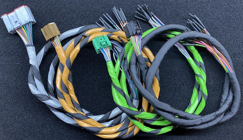
SAFETY NOTICE
This publication’s purpose is to provide technical training information to individuals in the
automotive trade. All test and repair procedures must be performed in accordance with
manufacturer’s service and diagnostic manuals. All warnings, cautions, and notes must be
observed for safety reasons. The following is a list of general guidelines:
Proper service and repair is critical to the safe, reliable operation of all motor vehicles.
The information in this publication has been developed for service personnel, and can help
when diagnosing and performing vehicle repairs.
Some service procedures require the use of special tools. These special tools must be used
as recommended throughout this Technical Training Publication, the diagnostic manual, and
the service manual.
Special attention should be exercised when working with spring- or tension-loaded
fasteners and devices such as E-Clips, circlips, snap rings, etc. Careless removal may cause
personal injury.
Always wear safety goggles when working on vehicles or vehicle components.
Improper service methods may damage the vehicle or render it unsafe.
Observe all warnings to avoid the risk of personal injury.
Observe all cautions to avoid damage to equipment and vehicles.
Notes are intended to add clarity and should help make your job easier.
Cautions and warnings cover only the situations and procedures Stellantis has encountered and
recommended. Neither Stellantis nor its subsidiaries or affiliates can know, evaluate, and advise
the service trade of all conceivable ways in which service may be performed, or of the possible
hazards for each. Consequently, Stellantis and its subsidiaries and affiliates have not
undertaken any such broad service review. Accordingly, anyone who used a service procedure
or tool that is not recommended in this publication must be certain that neither personal
safety, nor vehicle safety, is jeopardized by the service methods they select.
No part of this publication may be reproduced, stored in a retrieval
system or transmitted, in any form or by any means, electronic,
mechanical, photocopying, recording, or otherwise, without the prior
written permission of Stellantis.
Stellantis reserves the right to make changes from time to time,
without notice or obligation, in prices, specifications, colors and
materials, and to change or discontinue models. See your dealer for
the latest information.
Copyright © 2021 Stellantis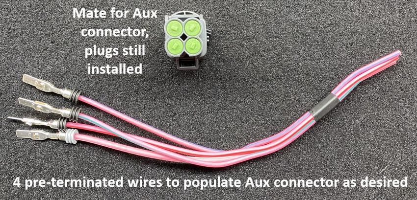
TABLE OF CONTENTS
ABOUT THIS GUIDE ......................................................................................................................... 1
FLEET WEBSITE ................................................................................................................................ 2
VEHICLE DIMENSIONS ..................................................................................................................... 3
ELECTRICAL...................................................................................................................................... 4
   CAN Communication and Cybersecurity ..................................................................................... 4
   Radar or other aftermarket CAN bus connections ..................................................................... 4
   Basic Electrical Tips ..................................................................................................................... 5
   Fuses / Power Distribution Center .............................................................................................. 7
   Power and Ground .................................................................................................................... 11
   Pass Through Circuits ................................................................................................................ 14
   4-way Underhood Aux Connector............................................................................................. 16
   26-way Upfitter connector ........................................................................................................ 19
VEHICLE SYSTEMS INTERFACE MODULE (VSIM) ........................................................................... 21
   Upfitter CAN bus ....................................................................................................................... 23
   24-way Gray VSIM connector.................................................................................................... 30
   16-way Black VSIM connector ................................................................................................... 31
   16-way Brown VSIM connector................................................................................................. 32
   16-way Green VSIM connector ................................................................................................. 33
LIGHTING ....................................................................................................................................... 34
   Red/White Dome Lamp ............................................................................................................. 34
   Spot Lamps ................................................................................................................................ 35
RESTRAINTS ................................................................................................................................... 38
   Occupant Restraint System Overview ....................................................................................... 38
   Driver Airbag (DAB) Deployment Zone ..................................................................................... 40
   Side Curtain Deployment Zone ................................................................................................. 42
   Passenger Airbag Deployment Zone ......................................................................................... 44
   Occupant Restraint System Wiring ........................................................................................... 47
   Occupant Restraint System Verification ................................................................................... 47
VEHICLE STORAGE ......................................................................................................................... 48
   General Storage Recommendations ......................................................................................... 48
   Battery Maintenance ................................................................................................................ 49
   Shipping Mode .......................................................................................................................... 50
ABOUT THIS GUIDE
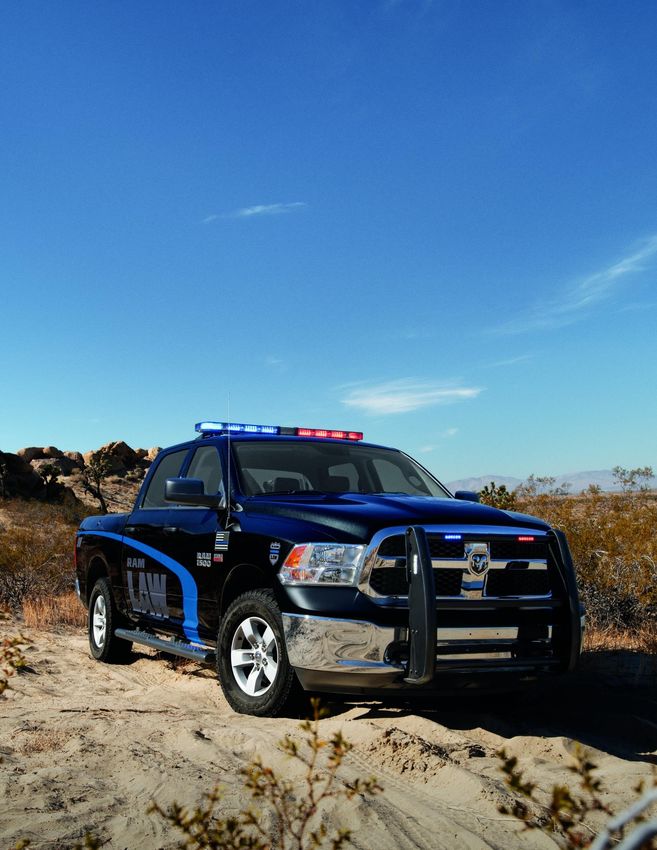
Figure 1: RAM 1500 SSV Interior with aftermarket equipment
This guide has been assembled to give facilities technical information on the RAM 1500 Special
Service Vehicle (SSV) that may be required when installing accessories or equipment for use in
fleet applications. Not all vehicles purchased are equipped with the same accessories, so there
may be items covered in this guide that are not featured on the vehicle purchased by your
organization.
RAM 1500 SSV Upfitter Guide 1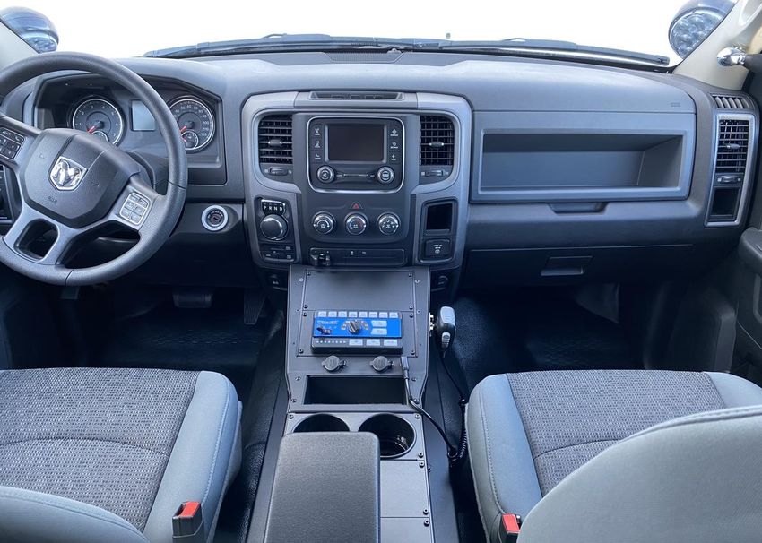
FLEET WEBSITE

                   Figure 2: Fleet Website, aftermarket equipment shown

The Fleet website is another resource for up-to-date specification information on the RAM 1500
SSV and other fleet vehicles. An electronic copy of additional upfitter information, as well as
options and service recommendations, are also found at www.fcausfleet.com.

RAM 1500 SSV Upfitter Guide                                                                  2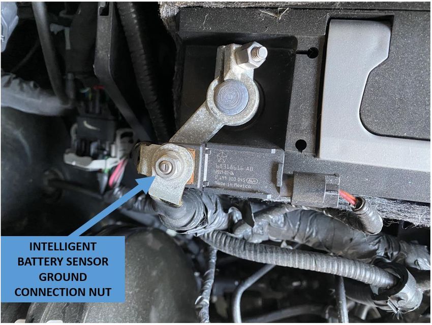
VEHICLE DIMENSIONS

                                 Figure 3: Vehicle Dimensions

                       A.     Length              5819.4 mm (229.1 in.)
                       B.     Front overhang      1017.3 mm (40.1 in.)
                       C.     Wheelbase           3569.2 mm (140.5 in.)
                       D.     Rear overhang       1233 mm (48.5 in.)
                       E.     Height              1942.8 mm (76.5 in.)
                       F.     Width               2008.7 mm (79.1 in.)

RAM 1500 SSV Upfitter Guide                                               3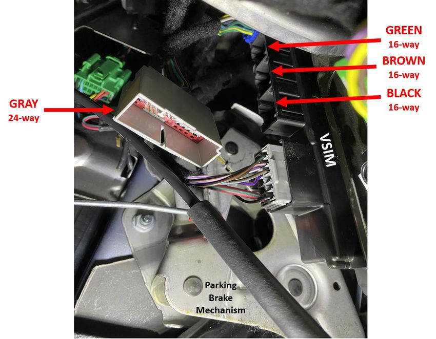
ELECTRICAL
CAN Communication and Cybersecurity

The vehicle security gateway blocks unauthorized CAN communication from the vehicle
diagnostic connector. Legislated/regulated diagnostic modes $01-$0A under SAE J1979 are still
fully supported for aftermarket tools.

Radar or other aftermarket CAN bus connections

Radar speed measuring equipment or other police equipment may require a connection to the
vehicle to determine the police vehicle’s speed. The RAM 1500 SSV provides two connection
methods for this purpose:
   1. A hardwired output from the Vehicle Systems Interface Module (VSIM) which gives
        vehicle speed as a square wave output. Refer to the section on the 16-way Black upfitter
        connector cavity 16 for more details on this signal.
   2. A CAN output from the VSIM upfitter bus which gives vehicle speed as a J1939 CAN
        signal. Refer to the section Upfitter CAN bus for more details on this connection.

CAUTION: Do not connect a radar unit or any other police equipment to the vehicle’s
         diagnostic connector or the vehicle operating CAN bus. These connections are
         designed only for authorized service tools during vehicle maintenance. Other
         equipment connected to the vehicle in this manner can induce unexpected faults
         and/or degraded vehicle performance and will not be covered by the vehicle’s
         manufacturer warranty.

NOTE:       There are sensors for the keyless entry and antilock brake systems, and an
            occupant restraint controller located between the front seats. If the vehicle is
            equipped with a front row center seat section, they are below that center section.
            Make sure during upfit that the sensors are not repositioned. Sensor placement is
            critical for proper system operation.

NOTE:       Do not remove the occupant restraint controller without first disconnecting the
            battery and waiting two minutes. Follow information in the Mopar Service Library
            for disabling the restraint system. Failure to do so could cause airbag deployment.

RAM 1500 SSV Upfitter Guide                                                                       4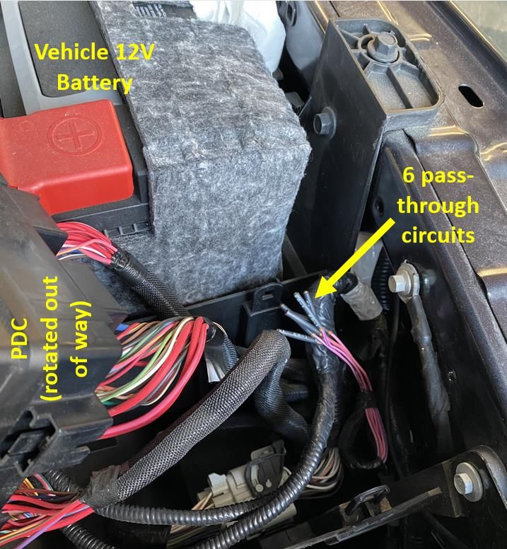
Basic Electrical Tips
ISO Relays
Figure 4: ISO Relays
ISO relays conform to the specifications of the International Organization for Standardization
for common size and terminal pattern. ISO relays are used in many applications such as the
starter, horn, electric fan, air conditioning clutch, auto shut down, and fuel pump circuits.
Relay connection terminals are defined as follows:
Terminal 30 is usually connected to battery voltage. This battery voltage source can be
switched on or off by the ignition switch, or un-switched, connected directly to the battery.
Terminal 87A is connected to Terminal 30 in the de-energized position.
Terminal 87 is connected to Terminal 30 in the energized position. When energized, the
relay supplies battery voltage to Terminal 87, or removes battery voltage from a device
connected to Terminal 87A.
Terminal 86 is connected to the electromagnet and is usually connected to a switched
battery voltage source.
Terminal 85 is connected to the electromagnet and is usually connected to a switched or
unswitched ground
RAM 1500 SSV Upfitter Guide 5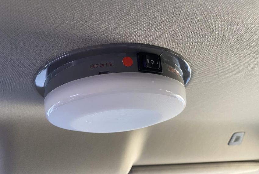
Micro Relays

                                     Figure 5: Micro Relays

Micro relays and micro 280 relays perform the same function as ISO relays but are smaller in
size and have different terminal patterns. A map of the pattern and terminal identification is
usually located on the top or side of the relay.

RAM 1500 SSV Upfitter Guide                                                                      6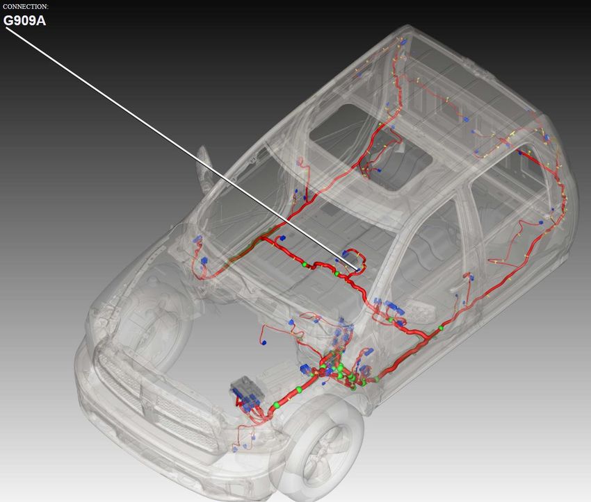
Fuses / Power Distribution Center

There are two fuse and relay locations on the vehicle for the standard electrical systems. The
fuse values and positions for the standard electrical systems are described below.

CAUTION:      When installing the Power Distribution Center (PDC) cover, make sure it is
              properly positioned and latched to prevent water from getting into the PDC and
              causing an electrical system failure. When replacing a blown fuse, use only a fuse
              having the correct amperage rating. The use of a fuse with a rating other than
              indicated may result in an electrical system overload. If a properly rated fuse
              continues to blow, it indicates a problem in the circuit that must be corrected.

                                    Figure 6: Underhood PDC

                                    Table 1: Underhood Fuses
Note: Fuse specifications may vary slightly from the table below and based on vehicle content,
      refer to the vehicle service information for the most current information.
     FUSE                                   FUNCTION                                  RATING
      F01    RADIATOR FAN CONTROL MODULE – IF EQUIPPED                                 80A
      F03    RADIATOR FAN – IF EQUIPPED                                                60A
      F05    AUX CONNECTOR RELAY OUTPUT 1                                              50A
      F06    ANTI-LOCK BRAKES/ELECTRONIC STABILITY CONTROL PUMP                        40A
      F07    STARTER SOLENOID                                                          40A
      F08    AUX CONNECTOR RELAY OUTPUT 4                                              40A
      F09    AUX CONNECTOR RELAY OUTPUT 3                                              40A
      F10    BODY CONTROLLER / EXTERIOR LIGHTING #2                                    40A
     F104    POWER OUTLETS (INSTRUMENT PANEL / CENTER CONSOLE)                         20A
      F11    INTEGRATED TRAILER BRAKE MODULE – IF EQUIPPED                             30A

RAM 1500 SSV Upfitter Guide                                                                      7
FUSE FUNCTION RATING
F12 BODY CONTROLLER #3 / POWER LOCKS 40A
F13 BLOWER MOTOR 40A
F14 BODY CONTROLLER #4 / INTERIOR LIGHTING 40A
F15 SPARE - (SPECIAL SERVICE VEHICLE) 30A
F19 SCR – IF EQUIPPED 20A
F20 PASSENGER DOOR MODULE 30A
F21 DRIVE TRAIN CONTROL MODULE 30A
F22 ENGINE CONTROL MODULE 20A
F23 BODY CONTROLLER #1 / INTERIOR LIGHTING 30A
F24 DRIVER DOOR MODULE 30A
F25 FRONT WIPER 30A
F26 ANTI-LOCK BRAKES / STABILITY CONTROL MODULE/VALVES 30A
F27 SPARE – (SPECIAL SERVICE VEHICLE) 25A
F28 TRAILER TOW BACKUP LIGHTS – IF EQUIPPED 20A
F29 TRAILER TOW PARKING LIGHTS – IF EQUIPPED 20A
F30 TRAILER TOW RECEPTACLE 30A
F31 UREA HEATER CONTROL – IF EQUIPPED (SPECIAL SERVICE VEHICLE) 20A
F32 SPARE 20A
F33 SPECIAL SERVICE VEHICLE ONLY 20A
F34 VEHICLE SYSTEM INTERFACE MODULE (VSIM) 30A
F35 RED/WHITE DOME LAMP 30A
F36 REAR DEFROSTER– IF EQUIPPED 30A
F37 AUX CONNECTOR RELAY OUTPUT 2 30A
F38 POWER INVERTER 115V AC – IF EQUIPPED 30A
F39 POWER OUTLET – (SPECIAL SERVICE VEHICLE) 20A
F41 ACTIVE GRILL SHUTTER IF EQUIPPED 10A
F42 HORN 20A
F44 DIAGNOSTIC PORT 10A
F46 UPFITTER – IF EQUIPPED 10A
F49 INSTRUMENT PANEL CLUSTER (EXCEPT SPECIAL SERVICE VEHICLES) 10A
F50 AIR SUSPENSION CONTROL MODULE – IF EQUIPPED 20A
IGNITION NODE MODULE / KEYLESS IGNITION (INSTRUMENT PANEL CLUSTER –
F51 10A
SPECIAL SERVICE VEHICLE)
F52 BATTERY SENSOR 5A
F53 TRAILER TOW – LEFT TURN/STOP LIGHTS 20A
F54 ADJUSTABLE PEDALS 20A
F55 SPOT LAMPS 25A
F56 ADDITIONAL DIESEL CONTENT – IF EQUIPPED 15A
F57 TRANSMISSION 20A
F59 SCR RELAY – IF EQUIPPED 10A
F60 UNDERHOOD LAMP 15A
F61 PM SENSOR – IF EQUIPPED 10A
F62 AIR CONDITIONING CLUTCH 10A
F63 IGNITION COILS 20A
F64 FUEL INJECTORS / POWERTRAIN 25A
RAM 1500 SSV Upfitter Guide 8FUSE FUNCTION RATING
F66 SUNROOF / PASSENGER WINDOW SWITCHES / RAIN SENSOR 10A
F67 CD / DVD / BLUETOOTH HANDS-FREE MODULE – IF EQUIPPED 10A
F70 FUEL PUMP MOTOR 30A
F71 AMPLIFIER 25A
F72 PCM – IF EQUIPPED 10A
F74 BRAKE VACUUM PUMP GAS / DIESEL – IF EQUIPPED 20A
F75 COOLANT TEMPERATURE VALVE ACTUATOR 10A
F76 ANTI-LOCK BRAKES / ELECTRONIC STABILITY CONTROL 10A
F77 DRIVETRAIN CONTROL MODULE / FRONT AXLE DISCONNECT MODULE 10A
F78 ENGINE CONTROL MODULE / ELECTRIC POWER STEERING 10A
F79 CLEARANCE LIGHTS 15A
F80 UNIVERSAL GARAGE DOOR OPENER / COMPASS 10A
F81 TRAILER TOW RIGHT TURN / STOP LIGHTS 20A
F82 STEERING COLUMN CONTROL MODULE / CRUISE CONTROL 10A
F84 SWITCH BANK / INSTRUMENT CLUSTER 15A
F85 AIRBAG MODULE 10A
F86 AIRBAG MODULE 10A
AIR SUSPENSION – IF EQUIPPED / TRAILER TOW / STEERING COLUMN CONTROL
F87 10A
MODULE
F88 INSTRUMENT PANEL CLUSTER 15A
F90 POWER OUTLET (REAR SEATS) CUSTOMER SELECTABLE 20A
F91 POWER OUTLET (REAR SEATS) CUSTOMER SELECTABLE 20A
F92 SPARE 10A
F93 CIGAR LIGHTER 20A
F94 SHIFTER / TRANSFER CASE MODULE 10A
F95 REAR CAMERA / PARK ASSIST 10A
F96 REAR SEAT HEATER SWITCH 10A
F97 REAR HEATED SEATS & HEATED STEERING WHEEL – IF EQUIPPED 25A
F98 FRONT HEATED SEATS – IF EQUIPPED 25A
F99 CLIMATE CONTROL 10A
RAM 1500 SSV Upfitter Guide 9Table 2: Underhood Relays
Note: Relay specifications may vary slightly from the table below and based on vehicle
content, refer to the service information for the most current information.
RELAY DESCRIPTION POPULATION
K01 RAD FAN LO SPD PLUG IN
K02 RAD FAN HI SPD PLUG IN
K03 AUXILIARY 1 PLUG IN
K04 AUXILIARY 4 PLUG IN
K05 AUTO SHUT DOWN (ASD) PLUG IN
K06 RUN / ACCESSORY 1 PLUG IN
K07 STARTER SOLENOID 2 PLUG IN
K08 RUN / START PLUG IN
K09 AUXILIARY 3 PLUG IN
K10 REAR WINDOW DEFOGGER PLUG IN
K12 RUN 2 PLUG IN
K13 AUXILIARY 2 PLUG IN
K14 RUN / ACCESSORY 2 PLUG IN
K15 RUN 1 PLUG IN
K16 BLOWER MOTOR PLUG IN
K17 TRAILER TOW – LEFT INTERNAL
K18 ADJUSTABLE PEDALS INTERNAL
K19 HORN INTERNAL
K21 POWERTRAIN MODULE INTERNAL
K23 A/C CLUTCH INTERNAL
K24 SCR 1 INTERNAL
K25 TRAILER TOW BACKUP LAMP INTERNAL
K26 TRAILER TOW PARK LAMP INTERNAL
K28 TRAILER TOW – RIGHT INTERNAL
K29 FUEL PUMP INTERNAL
K30 WIPER HIGH / LOW INTERNAL
K31 WIPER ON / OFF INTERNAL
K33 VACUUM PUMP INTERNAL
RAM 1500 SSV Upfitter Guide 10Power and Ground
NOTE: All equipment circuits connecting to vehicle circuits should be protected with fuses and
use industry accepted connection methods including weatherproofing where
appropriate.
NOTE: Any circuits connecting to existing vehicle signal wires should be high impedance and/or
isolated with relays to prevent unwanted interference with the vehicle signal. Wiring
locations described herein are for information only and it is up to the installer to ensure
that circuits chosen are suitable for the desired application and do not have a negative
impact on vehicle operation.
The following five power circuits are provided for aftermarket equipment. See the section for
the 26-way upfitter connector for more details:
(1) 10A circuit powered with ignition in ACCY or RUN
(1) 20A circuit powered with ignition in ACCY or RUN. This circuit can be converted to
battery fed.
(3) 20A battery fed
Four circuits in the underhood aux connector provide relay controlled power for aftermarket
equipment. See the section for the 4-way Underhood Aux Connector for more details:
(1) 30A customer driven
(1) 40A customer driven
(1) 40A driven with ignition in RUN or CRANK
(1) 50A customer driven
12V power can also be obtained at the vehicle battery, underhood.
Multiple grounding locations can be found and are visible underhood. In the cabin, grounding
locations can be found behind trim in the following locations:
1. Ring terminals within the instrument panel primarily on the driver’s side
2. Between the front seats or under front row center seat section, if equipped
A ground terminal is also at the rear of the vehicle on the frame, driver’s side just rearward of
the stabilizer link mount.
RAM 1500 SSV Upfitter Guide 11Figure 7: Grounding location between front seats RAM 1500 SSV Upfitter Guide 12
Figure 8: Grounding location at rear frame

RAM 1500 SSV Upfitter Guide                                          13
Pass Through Circuits

There are (6) unused 18 gauge wires available to the upfitter that are blunt cut in the
underhood area underneath the power distribution center (PDC) with the other end terminated
in the 26-way upfitter connector. See the 26-way Upfitter connector section for more
information. These wires are the preferred method to get power/signal circuits for aftermarket
equipment between the underhood area and the vehicle interior.

                          Figure 9: Pass-through circuits underhood

RAM 1500 SSV Upfitter Guide                                                                14
In the event additional pass-through capacity is necessary, most models have an unused port in
an existing grommet through the front of dash that can be used for passing through additional
wires for customer use. The port is currently sealed, if the tip is cut to pass additional wires
then it must be fully weather sealed afterward.
Figure 10: Grommet unused port
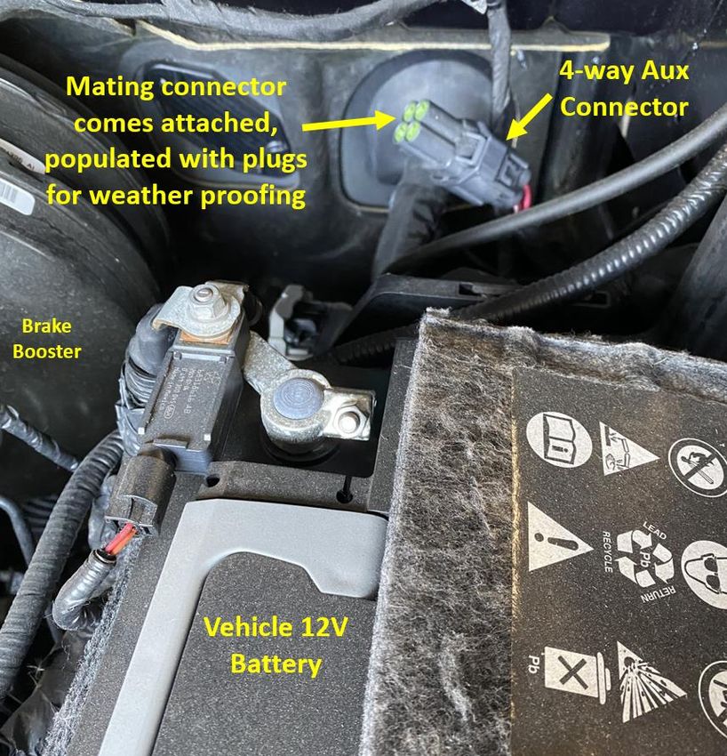
RAM 1500 SSV Upfitter Guide 154-way Underhood Aux Connector
Four circuits at the underhood aux connector provide relay controlled power for aftermarket
equipment. Packaged with the 26-way connector are 4 individual terminated wires that are
provided for use with this aux connector.
The mating connector is populated with 4 plugs and comes attached to the underhood aux
connector to provide weather sealing. To use any of these 4 circuits, remove the mating
connector from underhood, remove the plug(s) for the cavities desired, and populate those
cavities with the provided terminated wires.
Power capacity and details where the coil circuits are to energize each relay are shown in the
table below. The mechanization of the output at cavity 3 is such that it is energized anytime the
vehicle ignition is in RUN or CRANK.
Provided mating connector Vehicle harness connector
(view of wire entry side) (view of mating side)
Figure 11: 4-way Underhood Aux Connector
Table 3: 4-way Underhood Aux Connector
Max
Fuse # Relay #
Cavity Amperage High side of relay coil Low side of relay coil
in PDC in PDC
Output
1 50 5 K03 26-way cavity 8 26-way cavity 7
2 30 37 K13 26-way cavity 6 26-way cavity 5
3 40 9 K09 Hardwired to RUN/CRANK circuit Hardwired to GND
4 40 8 K04 26-way cavity 1 Hardwired to GND
RAM 1500 SSV Upfitter Guide 16Figure 12: 4 pre-terminated wires, come packaged with 26-way jumper RAM 1500 SSV Upfitter Guide 17
Figure 13: 4-way underhood Aux connector

RAM 1500 SSV Upfitter Guide                                       18
26-way Upfitter connector

          Note: This is the view of the vehicle harness connector, not the mating jumper/pigtail
                                   Figure 14: 26-way upfitter connector

Included mating jumper/pigtail 68225708AB (has 26-way white connector), package includes 4
individual terminated wires to use with 4-way underhood aux connector.

                               Table 4: 26-way upfitter connector pinout
                                                                                          MAX            CIRCUIT    WIRE
 CAVITY           SIGNAL                           USER DESCRIPTION                              GAUGE
                                                                                          AMPS              #      COLOR
   1          NO CONNECT
                                   When 12V is applied here, relay 4 in the PDC is
          RELAY 4 COIL HIGH-SIDE   activated. The low side of relay coil is already
   2                                                                                      9.5     20      P31      TN/YL
                CONTROL            tied to ground within the PDC. Relay 4 provides
                                   power at the 4-way aux connector underhood.
                                   Provides fused power when ignition is in RUN
   3       10A RUN/ACCY FEED                                                               10     16      F13       PK
                                   or ACCY (Fuse F92)
                                   Provides fused power when ignition is in RUN
                                   or ACCY. Note: if fuse 91 in the PDC is moved
   4       20A RUN/ACCY FEED                                                               20     16      F30      PK/YL
                                   to its alternate position, this circuit will provide
                                   a 20A battery feed. (Fuse F91)
          RELAY 2 COIL LOW-SIDE    When ground is applied to the low side of the
   5                                                                                      9.5     20      P675     TN/BK
                CONTROL            coil and 12V is applied to the high side, relay 2
          RELAY 2 COIL HIGH-SIDE   in the PDC is activated. Relay 2 provides power
   6                                                                                      9.5     20      P674      TN
                CONTROL            at the 4-way aux connector underhood.
          RELAY 1 COIL LOW-SIDE    When ground is applied to the low side of the
   7                                                                                      9.5     20      P711      LG
                CONTROL            coil and 12V is applied to the high side, relay 1
          RELAY 1 COIL HIGH-SIDE   in the PDC is activated. Relay 1 provides power
   8                                                                                      9.5     20      P712     LG/WT
                CONTROL            at the 4-way aux connector underhood.
   9           NO CONNECT
  10           NO CONNECT
  11        20A BATTERY FEED       Provides fused battery power (Fuse F32)                 20     16      A988     RD/WT
  12        20A BATTERY FEED       Provides fused battery power (Fuse F31)                 20     16      A984     RD/YL
  13           NO CONNECT
  14      PASS-THROUGH CIRCUIT                                                            13.5    18      F601     PK/DB
  15      PASS-THROUGH CIRCUIT                                                            13.5    18      F602     PK/DG
  16      PASS-THROUGH CIRCUIT     Pass through wires that terminate under the            13.5    18      F603     PK/VT
  17      PASS-THROUGH CIRCUIT     underhood PDC                                          13.5    18      F604     PK/TN
  18      PASS-THROUGH CIRCUIT                                                            13.5    18      F605     PK/BR
  19      PASS-THROUGH CIRCUIT                                                            13.5    18      F606       PK
  20        20A BATTERY FEED       Provides fused battery power (Fuse F33)                 20     16      A983     RD/LG
  21           NO CONNECT

RAM 1500 SSV Upfitter Guide                                                                                              19
MAX CIRCUIT WIRE
CAVITY SIGNAL USER DESCRIPTION GAUGE
AMPS # COLOR
22 AUX SWITCH 1 9.5 20 P820 BR/OR
Circuits terminate at the IP switch bank
23 AUX SWITCH 2 9.5 20 P821 BR/VT
connector. Note: these cavities are not
24 AUX SWITCH 3 9.5 20 P822 BR/WT
populated on the provided mating jumper
25 AUX SWITCH 4 9.5 20 P823 BR/GY
harness.
26 AUX SWITCH 5 9.5 20 P824 TN/BR
RAM 1500 SSV Upfitter Guide 20VEHICLE SYSTEMS INTERFACE MODULE (VSIM)
Figure 15: VSIM Location
Figure 16: VSIM upfitter harness kit part number 68319578AA – gray, brown, green, black
RAM 1500 SSV Upfitter Guide 21Figure 17: VSIM upfitter harness connection locations RAM 1500 SSV Upfitter Guide 22
The microcontroller-based electronic Vehicle Systems Interface Module (VSIM) is located in the
instrument panel to the right of the parking brake mechanism. The VSIM contains the electronic
logic circuitry and software that enable many of the aftermarket equipment and systems
typically installed on police or fleet vehicles to communicate with and be integrated with the
electronic control modules and features already installed in the vehicle. It can communicate
with aftermarket modules or with other electronic modules in the vehicle using the Controller
Area Network (CAN) data bus.

The VSIM awakens or sleeps based upon the status of the CAN data bus network. The module
monitors both active and stored Diagnostic Trouble Codes (DTC) through On-Board Diagnostics
(OBD) and communicates with a diagnostic scan tool using the CAN data bus.

NOTE: The 12V and GND signals provided by the VSIM are low current I/O intended only to
      drive very small loads (such as an automotive relay) or provide input signals to your
      aftermarket equipment. For sourcing or sinking higher current, use the higher amperage
      circuits described within the Power and Ground section.

Upfitter CAN bus

The VSIM upfitter J1939 CAN bus (cavities 10 and 11 in the 24-way Gray VSIM connector)
supports the signals on the following pages. Not all signals are available in all applications.

RAM 1500 SSV Upfitter Guide                                                                       23
Table 5: VSIM upfitter bus standard SAE J1939 Output Messages
Signals provided by the VSIM to indicate current operating conditions
Parameter Suspect
Suspect Transmission
Group Parameter Group Parameter Source Destination Transmission
Parameter Repetition RAM Specific Information
Number Name Number Address Address Type
Name Rate (ms)
(PGN) (SPN)
ASR is RAM equivalent of
Electronic Stability Control.
Electronic Brake ASR Engine There is no differentiation
61441 561 11 0xFF 100 Cyclic
Controller 1 Control Active between engine and braking
control, both signals will be
active at the same time.
ASR is RAM equivalent of
Electronic Stability Control.
Electronic Brake ASR Brake There is no differentiation
61441 562 11 0xFF 100 Cyclic
Controller 1 Control Active between engine and braking
control, both signals will be
active at the same time.
Electronic Brake Antilock
61441 563 11 0xFF 100 Cyclic
Controller 1 Braking Active
This signal will be active
Electronic Brake ABS Amber
61441 1438 11 0xFF 100 Cyclic lamp indicator check that
Controller 1 Warning Signal
occurs at key on from off.
Accelerator
Electronic Engine
61443 91 Pedal Position 0 0xFF 50 Cyclic
Controller 2
1
Electronic Engine speed
61444 190 Engine Speed 0 0xFF Cyclic
Controller 1 dependent
Beltlock and Airbag
Driver Belt
64791 Deactivation Switch 4952 53 0xFF 250 Cyclic
Lock Status
Information
Beltlock and Airbag
Passenger Belt
64791 Deactivation Switch 4953 53 0xFF 250 Cyclic
Lock Status
Information
Operators External
Hazard Light Cyclic & On
64972 Light Controls 2875 33 0xFF 1000
Switch Change
Message
High Beam Cyclic & On
65088 Lighting Command 2348 33 0xFF 1000
Headlight Data Change
Low Beam Cyclic & On
65088 Lighting Command 2350 33 0xFF 1000
Headlight Data Change
Left Turn Cyclic & On
65088 Lighting Command 2368 33 0xFF 1000
Signal Lights Change
Right Turn Cyclic & On
65088 Lighting Command 2370 33 0xFF 1000
Signal Lights Change
Cyclic & On
65088 Lighting Command 2372 Left Stop Light 33 0xFF 1000
Change
Right Stop Cyclic & On
65088 Lighting Command 2374 33 0xFF 1000
Light Change
Center Stop Cyclic & On
65088 Lighting Command 2376 33 0xFF 1000
Light Change
Back - Up Light
Cyclic & On
65088 Lighting Command 2392 and Alarm 33 0xFF 1000
Change
Horn
Cyclic & On
65088 Lighting Command 2404 Running Light 33 0xFF 1000
Change
High
High Resolution Resolution Cyclic & On
65217 917 33 0xFF 1000
Vehicle Distance Total Vehicle Change
Distance
Flash
Active Diagnostic 3038
65226 Malfunction 0 0xFF 100 Cyclic
Trouble Codes (flash)
Indicator Lamp
RAM 1500 SSV Upfitter Guide 24Parameter Suspect
Suspect Transmission
Group Parameter Group Parameter Source Destination Transmission
Parameter Repetition RAM Specific Information
Number Name Number Address Address Type
Name Rate (ms)
(PGN) (SPN)
Malfunction
Active Diagnostic 1213
65226 Indicator Lamp 0 0xFF 100 Cyclic
Trouble Codes (on/off)
Status
Total Vehicle
65248 Vehicle Distance 245 33 0xFF 100 Cyclic
Distance
Vehicle
Vehicle Timing is not exact due to
65260 237 Identification 33 0xFF ~ 300 Cyclic
Identification bus translations.
Number (VIN)
EngineTemperature Engine Coolant
65262 110 0 0xFF 500 Cyclic
1 Temperature
Engine Fluid Engine Oil
65263 100 0 0xFF 200 Cyclic
Level/Pressure 1 Pressure
Cruise
Parking Brake
65265 Control/Vehicle 70 0 0xFF 100 Cyclic
Switch
Speed
Cruise
Wheel-Based
65265 Control/Vehicle 84 0 0xFF 100 Cyclic
Vehicle Speed
Speed
The last set speed value is
Cruise
Cruise Control broadcast in this message
65265 Control/Vehicle 86 0 0xFF 100 Cyclic
Set Speed whether the cruise control is
Speed
active or not.
When the value of this signal
Cruise
Cruise Control is '01' cruise control system
65265 Control/Vehicle 595 0 0xFF 100 Cyclic
Active is actively controlling vehicle
Speed
speed.
Cruise When the value of this signal
Cruise Control
65265 Control/Vehicle 596 0 0xFF 100 Cyclic is '01' the cruise control
Enable Switch
Speed enable switch is depressed.
Cruise
65265 Control/Vehicle 597 Brake Switch 0 0xFF 100 Cyclic
Speed
Cruise
Cruise Control
65265 Control/Vehicle 599 0 0xFF 100 Cyclic
Set Switch
Speed
Cruise
Cruise Control
65265 Control/Vehicle 600 0 0xFF 100 Cyclic
Coast Switch
Speed
Cruise Cruise Control
65265 Control/Vehicle 601 Resume 0 0xFF 100 Cyclic
Speed Switch
Cruise Cruise Control
65265 Control/Vehicle 602 Accelerate 0 0xFF 100 Cyclic
Speed Switch
Fuel Economy Engine Fuel
65266 183 0 0xFF 100 Cyclic
(Liquid) Rate
Barometric
65269 Ambient Conditions 108 33 0xFF 100 Cyclic
Pressure
Ambient Air Cyclic & On
65269 Ambient Conditions 171 33 0xFF 100
Temperature Change
Engine Air
65269 Ambient Conditions 172 Intake 33 0xFF 100 Cyclic
Temperature
Charging
Vehicle Electrical Cyclic & On
65271 167 System 33 0xFF 1000
Power 1 Change
Potential
Transmission
Transmission Fluids Cyclic & On
65272 177 Oil 3 0xFF 1000
1 Change
Temperature
Parking Brake
65274 Brakes 619 33 0xFF 1000 Cyclic
Actuator
RAM 1500 SSV Upfitter Guide 25Parameter Suspect
Suspect Transmission
Group Parameter Group Parameter Source Destination Transmission
Parameter Repetition RAM Specific Information
Number Name Number Address Address Type
Name Rate (ms)
(PGN) (SPN)
Cyclic & On
65276 Dash Display 96 Fuel Level 33 0xFF 1000
Change
Lock Status Of
64933 Door Control 2 3412 33 0xFF 100 Cyclic
Door 1
Open Status
64933 Door Control 2 3413 33 0xFF 100 Cyclic
Of Door 1
Lock Status Of
64933 Door Control 2 3415 33 0xFF 100 Cyclic
Door 2
Open Status
64933 Door Control 2 3416 33 0xFF 100 Cyclic
Of Door 2
Lock Status Of
64933 Door Control 2 3418 33 0xFF 100 Cyclic
Door 3
Open Status
64933 Door Control 2 3419 33 0xFF 100 Cyclic
Of Door 3
Lock Status Of
64933 Door Control 2 3421 33 0xFF 100 Cyclic
Door 4
Open Status
64933 Door Control 2 3422 33 0xFF 100 Cyclic
Of Door 4
Lock Status Of
64933 Door Control 2 3424 33 0xFF 100 Cyclic
Door 5
Open Status
64933 Door Control 2 3425 33 0xFF 100 Cyclic
Of Door 5
Illumination
Cab Illumination Cyclic & On
53248 1487 Brightness 33 0xFF 1000
Message Change
Percent
Engine Oil
Direct Lamp Control
64773 5099 Pressure Low 33 0xFF 1000 Cyclic
Data 1
Lamp Data
Fuel Economy Instanteneous
65266 184 0 0xFF 100 Cyclic
(Liquid) Fuel Economy
Eng Total
65253 Hours 247 Hours Of 0 0xFF 1000 Cyclic
Operation
65254 Time/Date 961 Hour 33 0xFF 1000 Cyclic
65254 Time/Date 960 Minutes 33 0xFF 1000 Cyclic
Used to
indicate the
65102 Position of Doors 1821 33 0xFF 100 Cyclic
actual position
of the doors.
RAM 1500 SSV Upfitter Guide 26Table 6: VSIM upfitter bus RAM Specific Output Signals
Signals provided by the VSIM to indicate current operating conditions
Parameter Suspect
Parameter Starting Transmission
Group Parameter Source Destination Size Data Data Data Transmission Signal
Group Suspect Parameter Name Priority Position Repetition
Number Number Address Address (bits) Description Resolution Range Type Description
Name (bit) Rate (ms)
(PGN) (SPN)
00' off Active when
Chrysler Cyclic & On
65280 100000 A/C Clutch Engaged 33 0xFF 7 0 1 01' clutch 1 bit = 2 states 0 to 1 1000 A/C clutch is
Interior Change
engaged engaged
Active when
A/C is
00' off
Chrysler Cyclic & On requested
65280 100001 A/C Select 33 0xFF 7 1 1 01' A/C 1 bit = 2 states 0 to 1 1000
Interior Change either by
requested
VSIM, MTC or
ATC HVAC
'000'
IGN_LK
'011'
Provides
IGN_OFF_A
status of
Chrysler CC 3 bits = 8 Cyclic & On
65280 100002 Ignition Position 33 0xFF 7 3 3 0 to 7 1000 igntition: off,
Interior '100 states Change
accessory,
'IGN_RUN
run, start
'101'
IGN_START
'111' SNA
00' no
Airbag
Follow "any
Chrysler deployed Cyclic & On
65280 100003 Air Bag Deployed 33 0xFF 7 2 1 1 bit = 2 states 0 to 1 1000 impact" signal
Interior 01' any Change
from ORC
Airbag
deployed
00' not
Follows
occupied
Passenger
Chrysler Passenger Occupant '01' 2 bits = 4 Cyclic & On
65280 100004 33 0xFF 7 6 2 0 to 3 1000 Occupant
Interior Detection System occupied states Change
detect sensor
'10' error
Sts from ORC
'11' sna
RAM 1500 SSV Upfitter Guide 27Parameter Suspect
Parameter Starting Transmission
Group Parameter Source Destination Size Data Data Data Transmission Signal
Group Suspect Parameter Name Priority Position Repetition
Number Number Address Address (bits) Description Resolution Range Type Description
Name (bit) Rate (ms)
(PGN) (SPN)
If X = 0 then
y=0
If X=1 then
y shall Follows duty
Chrysler
toggle Cyclic & On cycle of Wig
62581 Exterior 100005 Front Wig Wag 33 0xFF 7 0 1 1 bit = 2 states 0 to 1 1000
between 1 Change Wags like
Lights
and 0 with VSIM output
f=1.5Hz and
duty cycle =
50 %
If X = 0 then
y=0
If X=1 then
y shall Follows duty
Chrysler
toggle Cyclic & On cycle of Wig
62581 Exterior 100006 Rear Wig Wag 33 0xFF 7 1 1 1 bit = 2 states 0 to 1 1000
between 1 Change Wags like
Lights
and 0 with VSIM output
f=1.5Hz and
duty cycle =
50 %
Chrysler 00' under
Active when
Exterior 25 mph Cyclic & On
65281 100007 Howler Siren Disable 33 0xFF 7 3 1 1 bit = 2 states 0 to 1 1000 vehicle speed
Lights and 01' over 25 Change
is over 25mph
Horn mph
Chrysler
00' Horn off
Exterior Cyclic & On
65281 100008 Horn 33 0xFF 7 2 1 01' Horn 1 bit = 2 states 0 to 1 1000
Lights and Change
on
Horn
00' no door
lock
Chrysler command
Cyclic & On Follow VSIM
65282 Doors 100009 Door Lock Command 33 0xFF 7 0 1 01' door 1 bit = 2 states 0 to 1 1000
Change Logic
and Locks lock
command
active
00' no door
Input signal
unlock
from external
Chrysler command
device to Follow VSIM
65282 Doors 100010 Door Unlock Command 33 0xFF 7 1 1 01' door 1 bit = 2 states 0 to 1 1000
VSIM to Logic
and Locks unlock
vehicle
command
systems
active
RAM 1500 SSV Upfitter Guide 28Parameter Suspect
Parameter Starting Transmission
Group Parameter Source Destination Size Data Data Data Transmission Signal
Group Suspect Parameter Name Priority Position Repetition
Number Number Address Address (bits) Description Resolution Range Type Description
Name (bit) Rate (ms)
(PGN) (SPN)
Chrysler 0 No
Cyclic & On Command
65283 Interior 2551 CHY_INT_CMD.ACSelect 0xFF 0xFF 7 0 1 Command 1 bit = 2 states 0 to 1 1000
Change A/C select on
Command 1 Command
Command to
Chrysler 0 No
Cyclic & On mute all
65283 Interior 2551 CHY_INT_CMD.RadioMute 0xFF 0xFF 7 1 1 Command 1 bit = 2 states 0 to 1 1000
Change entertainmen
Command 1 Command
t audio
Chrysler
Exterior 0 No Command
CHY_ExLH_CMD.RrWigWa Cyclic & On
65284 Lights and 2551 0xFF 0xFF 7 0 1 Command 1 bit = 2 states 0 to 1 1000 rear wig wags
g Change
Horn 1 Command on
Command
Chrysler
Exterior 0 No Command
Cyclic & On
65284 Lights and 2551 CHY_ExLH_CMD.FtWigWag 0xFF 0xFF 7 1 1 Command 0 to 1 1000 front wig
Change
Horn 1 Command wags on
Command
Command to
mute all horn
requests.
Chrysler Remote
Exterior 0 No keyless entry
Cyclic & On
65284 Lights and 2551 CHY_ExLH_CMD.HornMute 0xFF 0xFF 7 2 1 Command 1 bit = 2 states 0 to 1 1000 horn chirps
Change
Horn 1 Command can only be
Command disabled via
the menu
settings in the
radio
Chrysler 0 No
Cyclic & On Command to
65285 Doors 2551 CHY_DrLk.LockCommand 0xFF 0xFF 7 0 1 Command 1 bit = 2 states 0 to 1 1000
Change lock door
and Locks 1 Command
Chrysler 0 No
CHY_DrLk.UnLockComman Cyclic & On Command to
65285 Doors 2551 0xFF 0xFF 7 1 1 Command 1 bit = 2 states 0 to 1 1000
d Change unlock door
and Locks 1 Command
RAM 1500 SSV Upfitter Guide 2924-way Gray VSIM connector
Figure 18: 24-way Gray VSIM connector
Included with VSIM wiring harness kit part number 68319578AA
Table 7: 24-way Gray VSIM connector pinout
CIRCUIT
CAVITY SIGNAL TYPE USER DESCRIPTION COLOR
#
1 NO CONNECT
2 HAZARD INDICATOR ON OUTPUT Get 12V max 500mA when hazard lamps are activated W719 WH/BU
TRANSMISSION NOT IN Get 12V max 500mA when transmission is in any gear besides
3 OUTPUT W504 BN
PARK Park
4 RIGHT TURN SIGNAL ON OUTPUT Get 12V max 500mA when right turn signal is illuminated W681 WH/DG
5 NO CONNECT VT/BG
Get 12V max 500mA when engine MIL is on (including non-
6 MIL LAMP ON OUTPUT W540 DG
fault conditions such as IGN ON with ENG OFF)
TRANSMISSION PARK
7 OUTPUT Get GND when transmission is in Park W700 YE/DB
SIGNAL
TRANSMISSION NEUTRAL
8 OUTPUT Get GND when transmission is in Neutral W701 DG/YE
SIGNAL
A/C CLUTCH ENGAGED
9 OUTPUT Get GND when A/C Clutch is engaged W652 BU/BN
SIGNAL
10 VSIM UPFITTER BUS + CAN 250 Kbps CAN+, refer to VSIM upfitter bus section W533 BN/DB
11 VSIM UPFITTER BUS - CAN 250 Kbps CAN-, refer to VSIM upfitter bus section W535 BN/BU
TRANSMISSION REVERSE
12 OUTPUT Get GND when transmission is in Reverse W702 DG/DB
SIGNAL
13 NOT USED Not Used
14 A/C SELECTED SIGNAL OUTPUT Get GND when A/C has been selected ON by the operator W689 BU/DG
15 NO CONNECT
TRANSMISSION DRIVE
16 OUTPUT Get GND when transmission is in Drive W703 DG/BU
SIGNAL
17 ANY DOOR AJAR SIGNAL OUTPUT Get 12V max 500mA when any door is ajar W720 VT/OG
PASSENGER SEAT BELT NOT
18 OUTPUT Get GND when passenger seat belt is not latched W706 DG/GY
LATCHED
PASSENGER SEAT OCCUPIED
19 OUTPUT Get GND when passenger seat is occupied W554 DG/VT
SIGNAL
20 NO CONNECT
21 NO CONNECT
22 NO CONNECT
23 NO CONNECT
24 NO CONNECT
RAM 1500 SSV Upfitter Guide 3016-way Black VSIM connector
Figure 19: 16-way Black VSIM connector
Included with VSIM wiring harness kit part number 68319578AA
Table 8: 16-way Black VSIM connector pinout
CIRCUIT
CAVITY SIGNAL TYPE USER DESCRIPTION COLOR
#
1 25MPH SPEED SIGNAL OUTPUT Get 12V when vehicle speed is 25 MPH or above W505 GN
2 HORN PAD SENSE OUTPUT Get 12V max 500mA when horn pad is pressed W513 BN/GY
3 LEFT TURN SIGNAL OUTPUT Get 12V max 500mA when left turn signal is illuminated W682 WH/BU
4 HIGH BEAM SIGNAL OUTPUT Get 12V max 500mA when high beams are illuminated W684 WH/VT
5 IGNITION OFF OUTPUT Get 12V max 500mA when ignition is OFF W735 PK
DRIVER SEAT BELT NOT Get 12V max 500mA when driver's seat belt is not latched (IGN
6 OUTPUT W710 GN/VT
LATCHED must be in RUN)
Pulse Width Modulated (PWM) between open circuit and
7 OIL PRESSURE SIGNAL OUTPUT ground, 100 Hz, linear with 0% PWM = 0 PSI, and 100% PWM = W707 VT/GY
147 PSI.
Pulse Width Modulated (PWM) between open circuit and
8 VOLTAGE GAUGE PWM OUTPUT ground, 100 Hz, linear with 0% PWM = 5V, and 100% PWM = W733 VT
18V.
Get 12V max 500mA when airbag deployment has occurred
9 AIRBAG DEPLOYED OUTPUT during current ignition cycle. Subject to vehicle electrical W685 GN/VT
system being intact after an impact.
Get 12V max 500mA when VTA is armed and alarming (horn
VEHICLE THEFT ALARM (VTA)
10 OUTPUT sounding and lamps blinking). VSIM will wake up and output W515 VT/BU
ALARMING
will activate if alarm is triggered.
Get 12V max 250mA when the brake pedal (service brake) is
11 BRAKE PEDAL PRESSED OUTPUT W726 DG/OG
pushed
12 POWER FEED ACCESSORY OUTPUT Get 12V max 500mA when ignition is in ACCY position W734 PK/GY
Get 12V max 500mA when ignition is in RUN or CRANK
13 POWER FEED RUN/CRANK OUTPUT W736 PK/YE
position
Pulse Width Modulated (PWM) between open circuit and
14 FUEL LEVEL SIGNAL OUTPUT ground, 100 Hz, linear with 0% PWM = empty tank, and 100% W538 DB/GN
PWM = full tank
Pulse Width Modulated (PWM) between open circuit and
15 ENGINE RPM SIGNAL OUTPUT ground, 0.2 Hz/RPM (12 pulses per minute per 1 RPM) @ 50% W744 BN/WT
duty cycle
Modulation between open circuit and ground, output with 10
16 VEHICLE MPH SPEED SIGNAL OUTPUT W524 BN/YE
Hz/MPH (600 pulses per minute per MPH) @ 50% duty cycle
RAM 1500 SSV Upfitter Guide 3116-way Brown VSIM connector
Figure 20: 16-way Brown VSIM connector
Included with VSIM wiring harness kit part number 68319578AA
Table 9: 16-way Brown VSIM connector pinout
CIRCUIT
CAVITY SIGNAL TYPE USER DESCRIPTION COLOR
#
Pulse Width Modulated (PWM) output between open
1 CLUSTER DIMMING SIGNAL OUTPUT circuit and ground, 100Hz, linear with 0% PWM = zero W521 OG/GY
intensity, and 100% PWM = full intensity.
Get GND for 500ms when a vehicle unlock all request is
made. The vehicle need not be awake. For unlock requests
2 DOOR UNLOCK ALL SIGNAL OUTPUT W722 DG/BG
initiated by a FOB, this output only activates with a 2x press
of unlock on the FOB.
Get GND cycling at 80 flashes per minute (1.333Hz square
AUXILIARY FRONT WIG WAG
3 OUTPUT wave @ 50% duty cycle) when front wig wags (cavity 12) W503 BG/VT
FLASHING SIGNAL
are requested on
Apply GND to lock doors. This input will wake up the vehicle
4 DOOR LOCK REQUEST INPUT and lock the doors as well as activate the VSIM lock output W686 BG/DG
(cavity 9)
Apply GND to unlock doors. This input will wake up the
5 DOOR UNLOCK REQUEST INPUT vehicle and unlock the doors as well as activate the VSIM W687 BG/BU
unlock output (cavity 2)
Apply GND to mute entertainment audio. Limited
6 RADIO MUTE INPUT W640 GY/DG
availability - works on sales code UA1, UAV and UAX radios.
7 NO CONNECT DB/GN
8 NO CONNECT
Get GND for 500ms when a vehicle door lock request is
9 DOOR LOCK SIGNAL OUTPUT W721 GN/BG
made. The vehicle need not be awake.
Get GND cycling at 80 flashes per minute (1.333Hz square
AUXILIARY REAR WIG WAG
10 OUTPUT wave @ 50% duty cycle) when rear wig wags (cavity 14) are W502 BG/BN
FLASHING SIGNAL
requested on
11 PARK BRAKE SIGNAL OUTPUT Get GND when park brake is set W725 DG/WH
Apply GND to actuate front wig wag lamps, vehicle front
12 FRONT WIG WAGS INPUT high beams, 80 flashes per minute (1.3 Hz square wave @ W500 BN/OG
50% duty cycle). Also actuates circuit W503 (cavity 3)
Apply GND to mute the horn during panic alarm, vehicle
13 HORN MUTE INPUT theft alarm and normal horn pad function. Does not mute W537 DB/YE
horn for remote keyless chirps.
Apply GND to actuate rear wig wag lamps. Also activates
14 REAR WIG WAGS INPUT W501 BN/VT
circuit W502 (cavity 10)
15 NO CONNECT
16 GROUND INPUT For use on VSIM digital inputs only W709 BK
RAM 1500 SSV Upfitter Guide 3216-way Green VSIM connector
Figure 21: 16-way Green VSIM connector
Included with VSIM wiring harness kit part number 68319578AA
Table 10: 16-way Green VSIM connector pinout
CIRCUIT
CAVITY SIGNAL TYPE USER DESCRIPTION COLOR
#
1 NO CONNECT
2 NO CONNECT GY
3 NO CONNECT
Apply GND to turn off rear Turn/Tail/Brake/License/Reverse/
REAR BULB OUT CHMSL/Cargo) bulb fault detection. Allows the use of rear LEDs in
4 INPUT W509 WH/BN
DETECTION OFF place of incandescent bulbs. May be grounded before or after
disconnecting the vehicles OEM incandescent bulbs.
5 NO CONNECT GY/OG
6 NO CONNECT GY/YE
7 LOW BEAM SIGNAL Get 12V when high beams are illuminated W683 WH/BN
8 NO CONNECT
9 NO CONNECT GN/DB
10 NO CONNECT
Apply GND to command the vehicle A/C system to be activated. If
the A/C isn't on, this input will activate the A/C compressor and turn
the vehicle HVAC blower to low speed. While this input is activated
11 A/C TURN ON INPUT the vehicle's blower speed control can be used to control but the W656 BU
blower, but A/C system cannot be turned completely off. When this
input is deactivated (ground removed), the vehicle's A/C controls
returns to normal operation.
SEPARATED REAR TAIL
12 INPUT Apply GND to change rear stop/turn lamps to turn only W546 BG/GY
LIGHTING
13 NO CONNECT GY/BN
ENGINE RUNNING
14 OUTPUT Get 12V max 500mA when engine RPM > 450 W522 DB/BG
HOUR METER
15 PARK LAMP SIGNAL OUTPUT Get 12V when park lamps are illuminated W699 WH/GN
16 NO CONNECT
RAM 1500 SSV Upfitter Guide 33LIGHTING
Red/White Dome Lamp
Figure 22: Dome Lamp
The RAM 1500 SSV is equipped with a red/white dome lamp. The dome lamp switch has three
positions. One side of the switch turns on white LED lights, the other side turns on red LED
lights, and the center position turns the lamp OFF. Always remember to return the dome light
switch to the OFF (center) position to prevent the vehicle battery from discharging.
RAM 1500 SSV Upfitter Guide 34Spot Lamps
Figure 23: Spot Lamp
If you choose to install spot lamp(s), you can find electrical connectors at the base of each
A-pillar with the connector taped back to the harness. See the figures below. There are
electrical connectors on both driver and passenger sides, and they include a ground and battery
feed. They are powered through a shared 25A fuse #55 in the underhood PDC.
CAUTION: The side curtain airbag is tethered in the area of the spot lamp. If drilling and
installing your own lamp, make sure the tether is not damaged during the install
and is properly reattached when the installation is complete.
RAM 1500 SSV Upfitter Guide 35Figure 24: Driver side spot lamp blunt cut circuits (view with trim panel below steering wheel
removed, looking from center of vehicle towards outboard left side)
RAM 1500 SSV Upfitter Guide 36Figure 25: Passenger side spot lamp blunt cut circuits (view with glove box removed, looking
from center of vehicle towards outboard right side)
RAM 1500 SSV Upfitter Guide 37RESTRAINTS
Occupant Restraint System Overview
WARNING: INSTALLING A CONVENTIONAL PRISONER PARTITION IS NOT RECOMMENDED
ON VEHICLES EQUIPPED WITH LEFT AND RIGHT SIDE CURTAIN AIRBAGS, AS
POLICE CAGES MAY INTERFERE WITH THE DEPLOYING AIRBAG. THE AREA
WHERE THE SIDE CURTAIN AIRBAG IS LOCATED SHOULD REMAIN FREE FROM
ANY OBSTRUCTIONS. ONLY INSTALL A PARTITION THAT IS DESIGNED TO BE
COMPATIBLE WITH SIDE CURTAIN AIRBAGS.
WARNING: YOUR VEHICLE IS EQUIPPED WITH LEFT AND RIGHT SIDE CURTAIN AIRBAGS,
AND CARE MUST BE TAKEN WHEN INSTALLING ANY TYPE OF ROOF
EQUIPMENT. DRILLING AND INSTLALLATION OF FASTENERS OR OTHER
EQUIPMENT THAT MAY INTERFERE WITH THE SIDE CURTAIN AIRBAGS AND
AIRBAG WIRING HARNESSES IS NOT PERMITTED. MAKE SURE THAT NO
EQUIPMENT OR FASTENERS ARE LOCATED IN THE AIRBAG DEPLOYMENT ZONE.
WARNING: DO NOT PLACE OBJECTS, OR MOUNT EQUIPMENT, IN FRONT OF THE AIRBAG
MODULE COVER OR IN FRONT OF THE SEAT AREAS THAT MAY COME IN
CONTACT WITH A DEPLOYING AIRBAG. FAILURE TO FOLLOW THIS
INSTRUCTION COULD RESULT IN PERSONAL INJURY.
WARNING: DO NO PLACE DASH, TUNNEL, OR CONSOLE-MOUNTED EQUIPMENT OUTSIDE
OF THE SPECIFIED ZONE. FAILURE TO FOLLOW THIS INSTRUCTION COULD
RESULT IN PERSONAL INJURY.
The occupant restraint system contains the following components:
Occupant restraint controller (ORC) module
Front and side impact sensors
Seat belt tensioners
Airbags:
o Driver airbag
o Driver side curtain airbag
o Passenger airbag
o Passenger side curtain airbag
There are four interior zones to be aware of:
Driver airbag deployment zone
Passenger airbag deployment zone
Two side curtain airbag deployment zones
RAM 1500 SSV Upfitter Guide 381 Front Impact Sensor 5 Occupant Restraint Controller (ORC)
2 Passenger Air Bag 6 Seat Belt Tensioner
3 Driver Air Bag 7 Acceleration Sensor
4 Pressure Sensor 8 Side Curtain Air Bag
Figure 26: Occupant Restraint System Components
RAM 1500 SSV Upfitter Guide 39Driver Airbag (DAB) Deployment Zone
1 Vertical Plane Passing Through the Center of the 4 Steering Wheel
Steering Wheel
2 331 mm (13 in.) 5 Driver Airbag Retainer/Housing
3 Vertical Plane Passing Through the Maximum Rearward 6 Driver Airbag Cushion
Point that the Driver Airbag Cushion Reaches
Figure 27: Driver Airbag Dimensions
NOTE: The illustration represents the maximum dynamic deployment shape.
Table 11: Driver Airbag Cushion Position
DAB (Driver Airbag) diameter when full 661 mm (26 in.)
DAB depth when full 305 mm (12 in.)
Maximum rearward displacement during fill 407 mm (16 in.)
RAM 1500 SSV Upfitter Guide 40Figure 28: Driver Airbag Deployed Shape
Table 12: Steering Column Tilt Position Range
±2 degrees from steering column tilt pivot point
~22.0 degrees from vertical is the normal position
1 Driver Airbag Cushion Lateral Deployment 2 Driver Seating Reference
Zone 686mm (27 in.)
Figure 29: Deployment Zone
RAM 1500 SSV Upfitter Guide 41Side Curtain Deployment Zone
1 Cross Sectional Area Side View 4 120 mm (4.75 in.)
2 120 mm (4.75 in.) 5 120 mm (4.75 in.)
3 508 mm (20 in.)
Figure 30: Side Curtain
1 560 mm (22.1 in.) 4 508 mm (20 in.)
2 955 mm (37.6 in.) 5 508 mm (20 in.)
3 80 mm (3.2 in.) 6 B-pillar
Figure 31: Side Curtain Deployment Zone
RAM 1500 SSV Upfitter Guide 42Use caution when installing equipment along the roof side rails to avoid drilling or installing fasteners in the side curtain airbag area. Also make sure that no equipment interferes with the airbag deployment areas. If additional wiring needs to be routed on the sides of the roof, take care that the installed harness does not impede the airbag deployment. Point fasteners used to attach roof-mounted equipment outward from the passenger compartment to minimize risk of head injury and to avoid altering the head impact protection system (FMVSS 201) that is standard on these vehicles. Do not allow fasteners to extend into the passenger compartment, even between the roof and headliner. RAM 1500 SSV Upfitter Guide 43
Passenger Airbag Deployment Zone

  1   Passenger Airbag Cushion                  4   Instrument Panel
  2   Vertical Plane from Point of Instrument   5   Vertical Plane Passing Through the
      Panel                                         Maximum Rearward Point that the
                                                    Passenger Airbag Cushion Reaches
  3   Passenger Airbag Module                   6 675 mm (26.6 in.)
                      Figure 32: Passenger Airbag Deployment Zone

NOTE: The illustration represents the maximum dynamic deployment shape.

RAM 1500 SSV Upfitter Guide                                                              44
Figure 33: Final Passenger Airbag Deployment Shape RAM 1500 SSV Upfitter Guide 45
1   119 mm (4.7 in.)                        3 756 mm (29.8 in.)
  2   Passenger Airbag Deployment Zone        4 Reference Point
                              Figure 34: Deployment Zone

                              Figure 35: Center Interior Area

   WARNING:      MAKE SURE ADEQUATE SPACE IS AVAILABLE FOR AIRBAG DEPLOYMENT.
                 MOUNTING ACCESSORIES AND EQUIPMENT INSIDE THE DEPLOYMENT
                 ZONES IMPEDES AIRBAG DEPLOYMENT.

RAM 1500 SSV Upfitter Guide                                                     46
CAUTION: It is imperative that all occupant restraint system components remain in their
original location and orientation. Any modification, removal, or relocation of
components may be detrimental to the occupant restraint system performance
and is prohibited. Any vehicle modifications that may affect the occupant
restraint system characteristics should be verified through vehicle
calibration/impact testing.
Occupant Restraint System Wiring
All occupant restraint system wiring must remain intact and may not be used for any other
purpose. This includes the driver and front passenger seat wiring. Any electrical connector that
is yellow is part of the occupant restraint system and should not be modified or used for other
purposes.
Occupant Restraint System Verification
After any modification work is complete, confirm the occupant restraint system readiness as
follows: turn the ignition key to the ON position. The airbag lamp in the instrument cluster
illuminates for 6 to 8 seconds, and then turns off. If the airbag lamp fails to illuminate,
repeatedly cycles on and off, or does not turn off, have the condition corrected by an
authorized dealership before shipping the vehicle to the customer.
RAM 1500 SSV Upfitter Guide 47VEHICLE STORAGE
General Storage Recommendations
If a vehicle is not immediately delivered to the customer, store the vehicle according to the
following guidelines:
Store the vehicle indoors, in a clean and dry place.
Check the engine coolant and anti-freeze protection.
Leave the parking brake in the OFF position
Check the vehicle tire pressures and inflate them to the maximum recommended levels. To
help avoid flat spotting, move the vehicle at least once a month so that a different portion
of the tire tread contacts the ground
If vehicles must be stored outside:
Avoid storage locations near obvious sources of industrial or environmental contamination
(such as trees, factories, steam or vapor vents, railroad tracks, etc.).
Maintain tight security to help prevent vandalism. Inspect the vehicle regularly to check for
such damage.
If the vehicle must be parked on an incline, park it with the front end higher than the rear.
This prevents hydrostatic lock caused by fuel draining into the engine.
Rinse the vehicle at least once a week. Wash away the snow more often because it can trap
harmful contaminants. Dry all horizontal surfaces.
Remove the negative battery cable by removing the ground connection nut to prevent
battery drain and possible damage.
Keep all windows closed, all doors locked, and all trim covers intact and in place.
Do not use chalk, crayon, or any marker containing abrasives on painted, plated, or glass
surfaces.
Use protective, thin, plastic film to avoid soiling seats when moving a vehicle.
RAM 1500 SSV Upfitter Guide 48Battery Maintenance
The negative battery cable should be removed from the intelligent battery sensor to prevent
draining the battery during extended vehicle storage. Only loosen the ground connection nut
from the intelligent battery sensor to remove the negative battery cable.
WARNING: THE BATTERY IN THIS VEHICLE HAS A VENT HOSE THAT SHOULD NOT BE
DISCONNECTED AND SHOULD ONLY BE REPLACED WITH A BATTERY OF THE
SAME TYPE (VENTED). FAILURE TO FOLLOW THIS WARNING CAN RESULT IN
SERIOUS OR FATAL INJURY.
Once a month:
Check the battery state for charge (at least 12.4 volts). Charge the battery as necessary to
help prevent freezing and deterioration.
Make sure that the battery vent tube is properly connected to the battery and to the floor
pan.
Figure 36: Intelligent Battery Sensor
RAM 1500 SSV Upfitter Guide 49Shipping Mode The RAM 1500 SSV body control module has a Shipping Mode for transporting or storing for a long period of time, and for the time between when the vehicle leaves the factory and is ready for use by the customer. The vehicle will come from the factory in Shipping mode. Turn the hazard lamps on and press/hold the up arrow on the steering wheel electronic vehicle information center (EVIC) controls until the vehicle enters or exits shipping mode. Note that this procedure is only possible while the vehicle has relatively low mileage. If the procedure fails, threshold mileage has most likely been exceeded. You can also enable/disable the vehicle from Shipping Mode by using the scan tool: go to BCM then Misc. functions. In all cases, if shipping mode is no longer available for a vehicle, to reduce battery drain follow the battery disconnection recommendation described in the battery maintenance section above. RAM 1500 SSV Upfitter Guide 50
Notes:

RAM 1500 SSV Upfitter Guide   51
The special service tools referred to herein are required for certain service operations. These
 special service tools or their equivalent, if not obtainable through a local source, are
 available through the following outlet:

                                 Telephone 1-855-298-2687
                          2801-80th Street Kenosha, WI 53143, U.S.A.
                                     FAX 1-855-303-8985

RAM 1500 SSV Upfitter Guide                                                                    52
No part of this publication may be reproduced, stored in a retrieval
system or transmitted, in any form or by any means, electronic,
mechanical, photocopying, recording, or otherwise, without the prior
written permission of Stellantis.
Stellantis reserves the right to make changes from time to time,
without notice or obligation, in prices, specifications, colors and
materials, and to change or discontinue models. See your dealer for
the latest information.
Copyright © 2021 Stellantis
Upfitter Guide Revision 4/22/2021
RAM 1500 SSV Upfitter Guide 53You can also read