PILOTS & ACCESSORIES - Bruin Pumps
←
→
Page content transcription
If your browser does not render page correctly, please read the page content below
Y
  PILOTS &

                    SECTION
ACCESSORIES

   www.kimray.com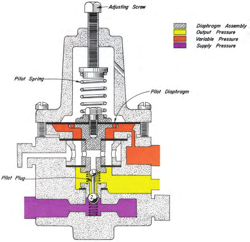
NOTE: We reserve the right to modify or change, without prior
notice, any statement or information contained herein. If exact dimen-
sions or specifications are required by the customer
certified prints will be furnished for a minimum charge upon request
to KIMRAY, Inc.
® Copyright 1992, KIMRAY, Inc.

                           www.kimray.com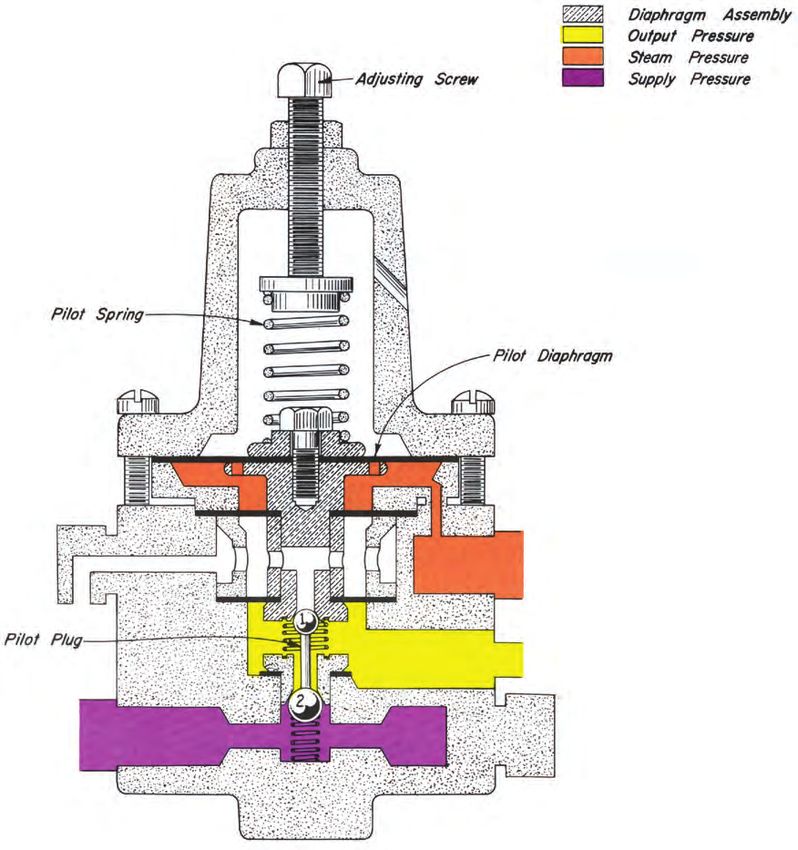
PILOTS AND ACCESSORIES
                                                                                                                    TABLE OF CONTENTS

                         SIGNAL PILOTS
   Kimray signal pilots enhance a pneumatic or mechanical                    FLOATLESS LIQUID LEVEL CONTROLLER__190.1
signal providing a reversed, multiplied, volume boosted or on-off            Controls 0 to 30 feet of water in vessels up to 125 psig. supply
signal pressure to operate motor valves, burners or dump valves.             a signal to open or close a diaphragm operated motor valve.
SNAP__________________________________ 10.1                                  PRESSURE REDUCING TO ATMOSPHERE______195.1
Change and reverse a varying pneumatic signal to an On-Off                   Regulate .5 oz. to 20 psig from a greater upstream pressure,
signal of the same or higher pressure. 3 PS                                  125 psig. 12 PG OPRA
THROTTLE_____________________________ 20.1
Multiply and volume          boost    a    pneumatic    signal.
3 PG and 3 PGA                                                                                         ACCESSORIES
MANUAL RESET________________________ 40.1                                    FILTERS_________________________________200.1
Output is blocked and downstream vented when monitored                       Removes particulates from the gas line, 300 psig. F 30
pressure goes to zero. 3 PM
                                                                             FILTER POP VALVES______________________210.1
MANUAL RELAY_________________________ 50.1                                   Provides a small pressure relief at 30 psig. FPV 3
Manual control pilot that blocks and bleeds output pressure
when released. 3 PGMR                                                        DRIP POTS_______________________________220.1
                                                                             Collects condensation for removal from pressure lines, 0-4000
THROTTLE REVERSE____________________ 60.1                                    psig. DP 30/200/400
Reverse and multiply varying pneumatic signal. 3 PGRA
                                                                             CHECK VALVES__________________________230.1
THROTTLE PRESSURESTAT______________ 70.1                                     An in line check valve to prevent reverse flow, 1500 psig.
Reverse and multiply varying pneumatic signal with adjustable                CV 15
output pressure. 3 PGP
                                                                             SUPPLY GAS REGULATORS_______________240.1
BISTABLE______________________________ 80.1                                  Gas pressure reducing instrument regulators, 4000 psig.
Two temporary pneumatic signals operate pilot. One to turn
output on, one to turn output off. 3 PGB                                     PNEUMATIC SOLENOID___________________250.1
                                                                             For electrical control of a pneumatic pressure used to open and
RELAY_________________________________ 90.1                                  close a motor valve.
Used to switch 0 to 300 psig signal with 20 to 30 psig signal.
30 PGR                                                                       MAGNELATCH SOLENOID_________________260.1
                                                                             Used to operate a valve by using an electrical current pulse of
MECHANICAL__________________________ 100.1                                   0.02 milliseconds duration.
Mechanically operated signal pilot. 3 PM
                                                                             AIR MOTOR______________________________270.1
PRIORITY SIGNAL RELAY_______________ 110.1                                   Provides mechanical movement from pneumatic pressure, 125
By-pass a normal pneumatic signal with a higher priority signal.             psig. 455/-AL
4 POR
                                                                             COMPANION FLANGE SETS_______________280.1
                                                                             Provides installation of flanged valves in a threaded piping
                                                                             system, 125 psig.
                       CONTROL PILOTS
                                                                             SENSE LINE PROTECTOR_________________290.1
Kimray control pilots operate motor valves in pneumatic systems
                                                                             An adjustable, self-resetting, pressure limiting device to protect
of up to 1500 psig working pressure. In each Kimray control
pilot an upstream or downstream pressure is used to operate a                instrumentation from over pressurization.
remotely installed motor valve. The Kimray design incorporates a
variety of standard and custom configurations applicable to most
control systems.

PRESSURE REDUCING_____________________150.1
Supply a set downstream pressure from a greater upstream
pressure, 0-1500 psig. 12/30 PG PR and 30 HPG PR-D, 50
PG and 150 PG.

PRESSURE DIFFERENTIAL_________________170.1
Maintain a constant pressure differential between upstream
and downstream pressures, 0-300 psig. 12/30 PG PD and
100/200/400 PDC.

LIQUID DIFFERENTIAL PRESSURE_________180.1
Maintain a constant differential pressure between a wet gas
upstream pressure and a liquid or gas sensed pressure
(requires auxiliary dry supply gas if sensed pressure is wet),
0-300 psig. 30 PG LDP-D

Current Revision:                                                                                                                                Y:i
Change Logo                                                        www.kimray.com                                                       Issued 1/13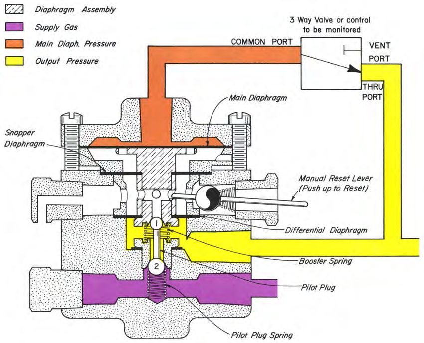
ELASTOMERS

              AFLAS    ®
                           is a trade mark of Asahi Glass Co                                         TEFLON (T)

  TEMPERATURE:                                                                 TEMPERATURE:
    +30° to +500° F                                                              -40° to +400° F
      0° to +260° C                                                              -20° to +204° C

  APPLICATION:                                                                 APPLICATION:
     Crude Oil & Gas Production (High heat), Steam                                Chemically Inert Elastomer Best in static Do not use at
  Flood Production Chemicals (corrosion inhibitors) Amine                      low temps
  Sweetener Systems, Gasoline, Diesel, Fuel Oil Systems
                                                                               FLUID / GAS:
  FLUID / GAS:                                                                   Almost All Chemicals
      Crude Oil & Gas Production, H2S, Steam, Petroleum
  fluids, Sea Water
                                                                                              VITON   ®
                                                                                                          is a trade mark of Dupont

                           HSN (HNBR)                                          TEMPERATURE:
                                                                                 -10° to +350° F
  TEMPERATURE:                                                                   -23° to +177° C
    -15° to +300° F
    -26° to +149° C                                                            APPLICATION:
                                                                                  Crude Oil & Gas Production, Glycol Dehydrators,
  APPLICATION:                                                                 Gasoline, Jet Fuel & Diesel Fuel Pumping, Water Disposal,
    Crude Oil & Gas Production w/ H2S, Wet C02                                 Methanol Injection Pumps. (Also Vacuum Service) (Gas
                                                                               permeability is very low)
  FLUID / GAS:
    Crude Oil & Gas, H2S, Wet C02, Sea Water                                   FLUID / GAS:
                                                                                   Crude Oil & Gas, H2S, Propane, Gasoline, Diesel, Fuel
                                                                               Oil Systems
                              NITRILE
                                                                               DO NOT USE WITH:
  TEMPERATURE:
                                                                                 Hot Water, Not preferred for wet CO2, Methyl Alcohol,
    Buna-N:
                                                                               Amines, Sodium hydroxide solutions
    -40° to +220° F
    -40° to +105° C
                                                                                                POLYURETHANE (P)
    Low-Temp:
    -85° to +120° F
                                                                               TEMPERATURE:
    -65° to +49° C
                                                                                 -40° to +220° F
                                                                                 -40° to +104° C
  APPLICATION:
    Crude Oil & Gas Production Glycol Dehydrators,
                                                                               APPLICATION:
  Gasoline, Jet Fuel & Diesel Fuel Pumping, Water Disposal,
  Methanol Injection Pumps, Water pump seals, hydraulic                          High abrasion resistance Seats, Diaphragms
  pump seals
                                                                               FLUID / GAS:
  FLUID / GAS:                                                                    Crude Oil gas and Water, H2S, propane, butane, fuel,
       Crude Oil & Gas, Good to Poor in Sour Production (See                   mineral oil and grease
  HSN), Water, Glycols, Hydraulic Oils, Resistance to crude
  oil in the presence of H2S and amines, Diesel fuel, fuel oils

  DO NOT USE WITH:
     Aromatic hydrocarbons, chlorinated hydrocarbons,
  phosphate esters (hydraulic fluids)

Y:ii                                                                                                                                 Current Revision:
Issued 9/14                                                       www.kimray.com                          Correct Sour Gas & Remove EP and H from list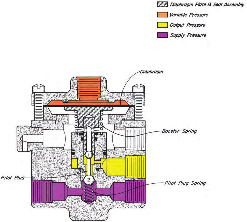
PILOTS AND ACCESSORIES
                                                                                                               3PS SNAP PILOTS

APPLICATIONS:                                                       OPERATION:
   Any system in which it is desired to change and reverse a             Assume Variable Pressure (Orange) is at a minimum and
varying pneumatic signal to an Output signal of the same or         the Diaphragm Assembly in an up position. An increase in
higher pressure (up to 4:1).                                        Variable Pressure (Orange) on the MAIN DIAPHRAGM sufficient
                                                                    to overcome load of the BOOSTER SPRING plus the force of
FEATURES:                                                           Supply Gas Pressure (Violet) on the full area of the SNAPPER
                                                                    DIAPHRAGM, the Diaphragm Assembly starts to move down.
   Pneumatic snap action
                                                                    The upper seat, which is the Supply Gas inlet (Violet to Yellow),
   No dead center
                                                                    closes first. The PILOT PLUG SPRING holds the upper ball
   Reverse Action
                                                                    against its seat while a further downward movement opens the
                                                                    lower seat which is the pressure vent (Yellow to Atmosphere).
SUPPLY PRESSURE:                                                    Decreasing Output Pressure (Yellow) accelerates the downward
   5 to 30 psig                                                     movement of the Diaphragm Assembly to produce a sudden
                                                                    opening of the pressure vent.
VARIABLE PRESSURE (input signal):                                        In order to reverse the above action, Variable Pressure
   0 - 10 psig minimum                                              (Orange) must be reduced so that the downward force on
   0 - 30 psig maximum                                              the MAIN DIAPHRAGM is less than the upward force on the
                                                                    BOOSTER SPRING plus Supply Gas Pressure (Violet) acting
                                                                    on the difference in areas of the SNAPPER and DIFFERENTIAL
VARIABLE PRESSURE SNAPPING RANGE:                                   DIAPHRAGMS. With upward movement of the Diaphragm
   Depends on Supply Pressure                                       Assembly the pressure vent (Yellow to Atmosphere) closes
   Approximately 2 - 7 psig at 30 psig                              first. The PILOT PLUG SPRING holds the lower ball against
                                                                    its seat while a further upward movement of the Diaphragm
OUTPUT PRESSURE:                                                    Assembly opens the Supply Gas Pressure inlet (Violet to
   0 psig or Supply Pressure                                        Yellow). As Output Pressure (Yellow) increases pressure
                                                                    across the DIFFERENTIAL DIAPHRAGM is reduced, loading
                                                                    the Diaphragm Assembly in an up direction. The accelerated
                                                                    upward movement of the Diaphragm Assembly produces a sud-
                                                                    den opening of the Supply Gas Pressure inlet (Violet to Yellow).

                      Diaphragm Assembly
                      Supply Pressure
                      Variable Pressure
                      Output Pressure

                                                               Main Diaphragm

                                                                  Snapper Diaphragm

Differential
Diaphragm
                                                                  Booster Spring

                                                                  Pilot Plug
               Pilot Plug
                   Spring

                                                                                Kimray is an ISO 9001- certified manufacturer.
Current Revision:                                                                                                                 Y:10.1
Change Logo                                              www.kimray.com                                                      Issued 1/13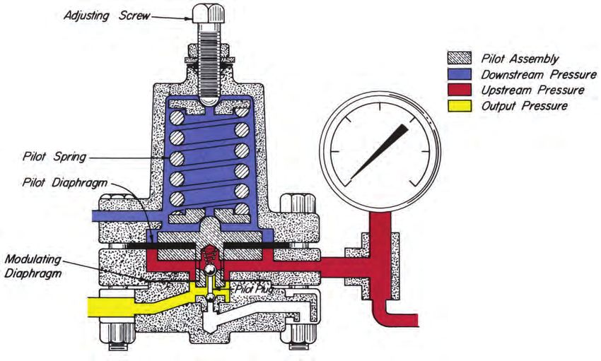
PILOTS AND ACCESSORIES
3 PS SNAP PILOTS
CAST IRON

                                                         2 3/4"

                          Cover 577                                                                     Diaphragm 582 *

                     Housing 578                                                                        Screw 573, 6 Req’d.
        1 1/2"

                         Spool 580                                                                      Plate 579

                 * Diaphragm 584                                                                        Diaphragm 583 *

                           Seat 113                                                                     Spacer 581

                         Spring 566                                                                     Gasket 118 *
         2"

                          Seat 565                                                                      Body 587

                    Pilot Plug 112                                                                      Spring 585

                          Plug 699
                                                                                                        Breather Plug 147

  PILOTS AVAILABLE:
CAT.		                            MAX      OPER.                  For steel and stainless steel, see 3 PG, this section.
NO.  PILOT                        W.P.     PRES.   KIT
                                                                  All openings are tapped 1/4" N.P.T.
YAG               3 PS                30    30     RMA
                                                                  *These parts are recommended spare parts and are stocked as
                                                                  repair kits.

                                                                              Kimray is an ISO 9001- certified manufacturer.
Y:10.2                                                                                                                    Current Revision:
Issued 1/13                                         www.kimray.com                                                           Change Logo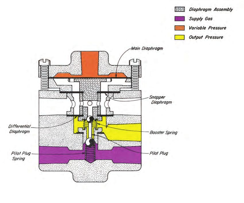
3PG THROTTLE PILOTS

APPLICATIONS:                                                           OPERATION (Described for Throttle Action):
   Any system in which it is desired to multiply and volume boost           Variable Pressure (Orange) acting on the MAIN DIAPHRAGM
a pneumatic signal to a large motor valve or similar equipment.         is the actuating force of the pilot. The counteracting force is
Amplification of the input pneumatic signal is approximately 4:1.       the Output Pressure (Yellow) acting on the DIFFERENTIAL
                                                                        DIAPHRAGM plus the BOOSTER SPRING. When Variable
FEATURES:                                                               Pressure (Orange) is zero, the Diaphragm Assembly is held
                                                                        in an up position by the BOOSTER SPRING. As Variable
    Pneumatic throttle
                                                                        Pressure (Orange) increases slightly to overcome the load of the
    Direct action
                                                                        BOOSTER SPRING, the Diaphragm Assembly moves down-
    Field reversible
                                                                        ward to first close the upper seat which is the pressure vent
    (See 3 PS for snap action)
                                                                        (Yellow to Atmosphere). The lower seat, which is the Supply
                                                                        Gas inlet (Violet to Yellow), has not yet opened, so both seats
SUPPLY PRESSURE:                                                        are closed with the PILOT PLUG. If Variable Pressure (Orange)
    5 to 30 psig                                                        increases still further, the Supply Gas inlet (Violet to Yellow)
                                                                        opens to increases the Output Pressure (Yellow) only sufficiently
VARIABLE PRESSURE:                                                      to balance the added Variable Pressure (Orange) acting on the
    0 to 30 psig                                                        MAIN DIAPHRAGM.
                                                                            With the Diaphragm Assembly in a balanced position any
                                                                        increase or decrease in Variable Pressure (Orange) will produce
OUTPUT PRESSURE:                                                        a proportional change in Output Pressure (Yellow) by opening
    Snap - 0 psig or Supply Pressure                                    either the Supply Gas inlet or the Output Pressure vent to re-
    Throttle - Variable (0 - 30 psig)                                   establish the balance.
                                                                            The 3 PG Pilot is actually a pressure multiplier and volume
                                                                        booster. Output pressure (Yellow) is approximately 4 times the
                                                                        Variable Pressure (Orange). Output Pressure (Yellow) accu-
                                                                        rately follows small changes in Variable Pressure (Orange) to
                                                                        properly position motor valves, etc. for throttling control.
                                                                            For Snap Service, the 3 PG Pilot operates as described for
                                                                        the 3 PS Pilot on Page 40.1.

                                                                                   Kimray is an ISO 9001- certified manufacturer.
Current Revision:                                                                                                                    Y:20.1
Change Logo                                                  www.kimray.com                                                     Issued 1/13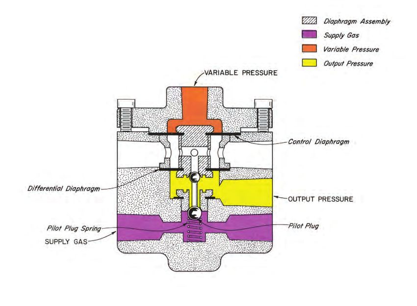
PILOTS AND ACCESSORIES
3PG THROTTLE PILOTS
DUCTILE / STEEL / 316SS

  PILOTS AVAILABLE:                                   NOTES:
CAT.		                   MAX    OPER.              May be used as a 3 PS by reversing the supply and vent con-
NO.  PILOT               W.P.   PRES.   KIT        nections.
YAE           3 PG        30     30     RMA
                                                   All openings are tapped 1/4" N.P.T.
YAE1          3 PG-S      30     30     RMA
YAGSS6        3 PG-SS6    30     30     RMA
                                                   *These parts are recommended spare parts and are stocked as
                                                   repair kits.

                                                               Kimray is an ISO 9001- certified manufacturer.
Y:20.2                                                                                                       Current Revision:
Issued 7/13                              www.kimray.com                               Consolidate steel and SS6 Body & Cover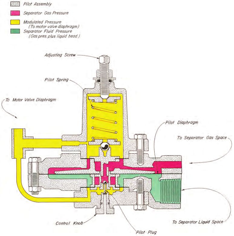
PILOTS AND ACCESSORIES
                                                                                                    3PGA THROTTLE PILOTS

APPLICATION:                                                        OPERATION (Described for Throttle Action):
  Any system in which it is necessary to volume boost a pneu-            Variable Pressure (Orange) acting on the CONTROL
matic signal to a large motor valve or similar equipment.           DIAPHRAGM is the actuating force on the pilot. The coun-
  As a volume amplifier for controls with a small feed volume.      teracting force is the Output Pressure (Yellow) acting on
                                                                    the DIFFERENTIAL DIAPHRAGM. When Variable Pressure
FEATURES:                                                           (Orange) is zero, the weight of the Diaphragm Assembly
                                                                    forces the upper seat, which is the pressure vent (Yellow to
   Volume boosts a pneumatic signal without a corresponding
                                                                    Atmosphere), closed. The lower seat, which is the Supply Gas
pressure boost (1:1 Output Pressure vs. Variable Pressure)
                                                                    inlet (Violet to Yellow), is slightly opened. This results in an
   Direct Action
                                                                    approximate Output Pressure (Yellow) of 2 psig. If Variable
   Pneumatic Throttle
                                                                    Pressure (Orange) increases, the Supply Gas inlet (Violet to
                                                                    Yellow) opens to increase the Output Pressure (Yellow) only suf-
SUPPLY PRESSURE:                                                    ficiently to balance the added Variable Pressure (Orange) acting
    5 to 30 psig                                                    on the CONTROL DIAPHRAGM.
                                                                         With the Diaphragm Assembly in a balanced position, any
VARIABLE PRESSURE:                                                  increase or decrease in Variable Pressure (Orange) will produce
    2 to 30 psig                                                    a proportional change in Output Pressure (Yellow) by open-
                                                                    ing either the Supply Gas inlet (Violet to Yellow) or the Output
                                                                    Pressure vent (Yellow to Atmosphere) to re-establish the bal-
OUTPUT PRESSURE:                                                    ance.
    Variable, 2 to 30 psig                                               The 3 PGA Pilot is actually a volume booster. Output
                                                                    Pressure (Yellow) is approximately 1 to 1 of Variable Pressure
                                                                    (Orange). Output Pressure (Yellow) accurately follows small
                                                                    changes in Variable Pressure (Orange) to properly position
                                                                    motor valves, etc. for throttling control.

                                                                               Kimray is an ISO 9001- certified manufacturer.
Current Revision:                                                                                                                Y:30.1
Change Logo                                               www.kimray.com                                                    Issued 1/13
PILOTS AND ACCESSORIES
3PGA THROTTLE PILOTS
DUCTILE / STEEL / 316SS

                                       RESPONSE GRAPH

  PILOTS AVAILABLE:                                    NOTES:
CAT.		                MAX      OPER.                All openings are tapped 1/4" N.P.T.
NO.  PILOT            W.P.     PRES.     KIT
                                                    *These parts are recommended spare parts and are stocked as
YAJ           3 PGA       30    30      RMA
                                                    repair kits.

                                                               Kimray is an ISO 9001- certified manufacturer.
Y:30.2                                                                                                     Current Revision:
Issued 1/13                               www.kimray.com                                                      Change Logo
PILOTS AND ACCESSORIES
3 PGM MANUAL RESET PILOTS
APPLICATION: OPERATION:
Any system where a 3 Way Valve is to be monitored and Assume that the 3 Way Valve to be monitored is “ON.” When
system supply is to be vented if a preset limit is exceeded. Supply Pressure (Violet) is connected, Ball 2 of the PILOT PLUG
is against the lower seat and prevents Supply Pressure (Violet)
FEATURES: from reaching the Output (Yellow).
The Diaphragm Assembly is held in a UP position by the
Intermittent vent pilot 3 Way Valving
BOOSTER SPRING. The upper seat and Ball 1 of the PILOT
Manual reset
PLUG are separated allowing the Output Pressure (Yellow)
Provides “tattle-tell” signal when preset limit is exceeded
to be vented. When the Reset Lever is manually raised, the
Rapid venting action
upper seat is closed and the lower seat is opened allowing
Direct acting
the Output Pressure (Yellow) to increase. This increase is
transferred to the MAIN DIAPHRAGM through the 3 Way Valve
SUPPLY PRESSURE: and holds the Diaphragm Assembly down allowing the Output
5 to 30 psig Pressure (Yellow) to equalize with the Supply Pressure (Violet).
The 3 PGM is now “LOCKED ” on and the Output Pressure
OUTPUT PRESSURE: (Yellow) equals the Supply Pressure (Violet). If the Output
0 psig or Supply Pressure Pressure (Yellow) is interrupted by the 3 Way Valve and the
Main Diaphragm Pressure (Orange) is vented through the 3
Way Valve, the Diaphragm Assembly will be pushed up by the
BOOSTER SPRING and the Output Pressure (Yellow) is vented
through the upper seat of the 3 PGM. The 3 Way Valve must be
reset to “ON ” and then the Reset Lever of the 3 PGM must be
manually raised to resume operation.
Kimray is an ISO 9001- certified manufacturer.
Current Revision: Y:40.1
Change bleed to vent www.kimray.com Issued 9/15PILOTS AND ACCESSORIES
3 PGM MANUAL RESET PILOTS
DUCTILE IRON / STEEL
PILOTS AVAILABLE: NOTES:
CAT. MAX OPER. All openings are tapped 1/4" N.P.T.
NO. PILOT W.P. PRES. KIT
For dimensions refer to PG. 20.2 this section
YAF 3 PGM 30 30 RMC
YAF1 3 PGM-S 30 30 RMC
*These parts are recommended spare parts and are stocked as
repair kits.
Kimray is an ISO 9001- certified manufacturer.
Y:40.2 Current Revision:
Issued 7/13 www.kimray.com Consolidate steel and SS6 Body & CoverPILOTS AND ACCESSORIES
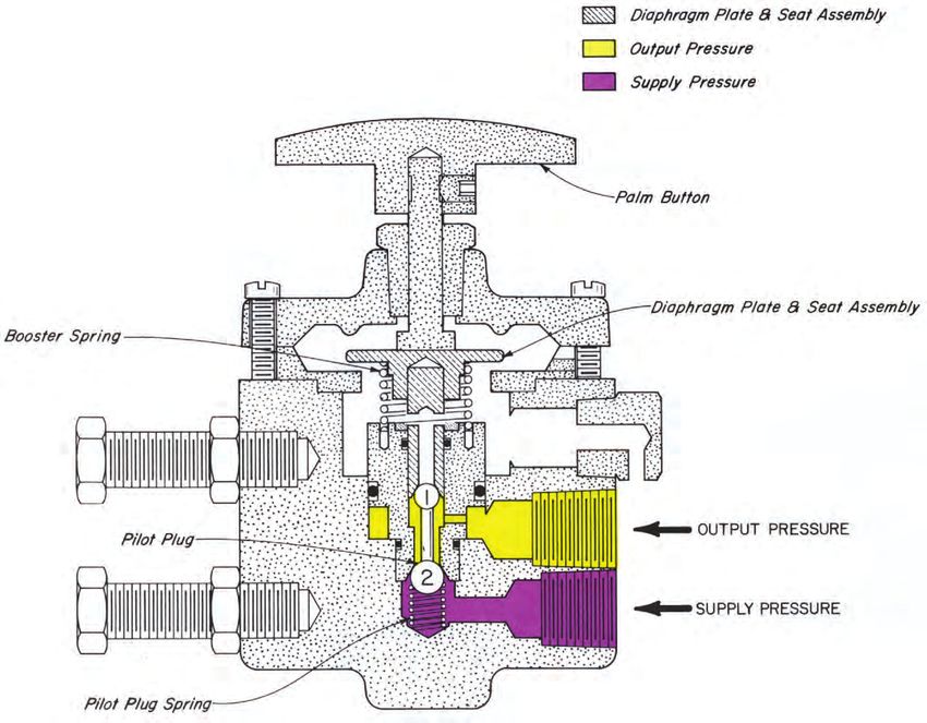
30 PGMR MANUAL RELAY PILOT
APPLICATION: OPERATION:
Manually sends a control signal to open or close a valve Manually depressing the PALM BUTTON causes the
using a palm button. Supply is blocked and control signal bled DIAPHRAGM PLATE and SEAT ASSEMBLY to close the upper
to vent when released. seat with Ball 1 of the PILOT PLUG. This blocks the vent, further
movement opens the lower seat at Ball 2 of the PILOT PLUG and
FEATURES: communicates Supply Pressure to the Output. Releasing the
PALM BUTTON reverses the action and allows the PILOT PLUG
Direct acting
SPRING to close the lower seat with Ball 2 removing the Supply
Mounting bolts for bracket mounting
Pressure from the Output. The BOOSTER SPRING then opens
Controls a relatively high pressure (300 psig) with minimal
the seat at Ball 1, venting the Output Pressure through the vent.
manual effort.
SUPPLY PRESSURE:
0 to 30 psig
OUTPUT PRESSURE:
0 psig or Supply Pressure
Kimray is an ISO 9001- certified manufacturer.
Current Revision: Y:50.1
Change bleed to vent www.kimray.com Issued 9/15PILOTS AND ACCESSORIES
30 PGMR MANUAL RELAY PILOT
DUCTILE IRON
DIMENSIONS
PILOTS AVAILABLE: NOTES:
CAT. MAX OPER. All openings are tapped 1/4" N.P.T.
NO. PILOT W.P. PRES. KIT
*These parts are recommended spare parts and are stocked as
YAL 30 PGMR-D 300 300 RMP
repair kits.
Kimray is an ISO 9001- certified manufacturer.
Y:50.2 Current Revision:
Issued 1/13 www.kimray.com Change LogoPILOTS AND ACCESSORIES
3PGRA THROTTLE - REVERSE PILOT
APPLICATION: OPERATION:
Any system in which it is desired to reverse and multiply a The PILOT SPRING loads the upper side of the Diaphragm
varying pneumatic signal. Assembly and is opposed by the Variable Pressure (Orange) act-
ing under the PILOT DIAPHRAGM and by the Output Pressure
FEATURES: (Yellow).
Assume the PILOT SPRING is compressed with the
Intermittent vent pilot
ADJUSTING SCREW set for a desired Variable Pressure
Reverse acting
(Orange). With the Variable Pressure (Orange) to low, the
Throttle action
PILOT SPRING holds the Diaphragm Assembly down, closing
Adjustable Steam Pressure
the upper seat at Ball 1 (Yellow to Atmosphere) and opening
the lower seat at Ball 2 (Violet to Yellow). As the Variable
SUPPLY PRESSURE: Pressure (Orange) increases to the set pressure, the Diaphragm
5 to 30 psig Assembly moves upward against the PILOT SPRING to first
close the lower seat at Ball 2 (Violet to Yellow) and then open the
OUTPUT PRESSURE: upper seat at Ball 1 (Yellow to Atmosphere). In this position the
0 to 20 psig Supply Pressure (Violet) inlet is closed and the Output Pressure
Adjustable Steam Pressure (Yellow) is vented to atmosphere.
PILOT SPRING #86 is furnished as standard. A heavier
spring (Part #692) can be furnished on special order, to raise the
VARIABLE PRESSURE (input signal): Variable Pressure (Orange) from 12 psig to 30 psig.
0 to 12 psig
30 psig maximum
PRESSURE RATIO:
(Orange to Yellow)
1.5:1
Kimray is an ISO 9001- certified manufacturer.
Current Revision: Y:60.1
Change bleed to vent www.kimray.com Issued 9/15PILOTS AND ACCESSORIES
3 PGRA THROTTLE-REVERSE PILOT
CAST IRON
PILOTS AVAILABLE: NOTES:
CAT. MAX OPER. †692 heavy spring available upon request.
NO. PILOT W.P. PRES. KIT
For dimensions refer to Pg. 70.2 of this section.
YAH 3 PGRA 30 30 RML
All openings are tapped 1/4" N.P.T.
*These parts are recommended spare parts and are stocked as
repair kits.
Kimray is an ISO 9001- certified manufacturer.
Y:60.2 Current Revision:
Issued 3/13 www.kimray.com Change Spring Plate numberPILOTS AND ACCESSORIES
3 PGP PRESSURESTAT
APPLICATION: OPERATION:
Direct firing of small steam generators by controlling flow of The PILOT SPRING loads the upper side of the Diaphragm
gas through the pilot to the burner. Approximate capacity of pilot Assembly and is opposed on the under side by the Steam
is 360 SCFH with 15 psig supply pressure. Pressure (Orange) and the Output Pressure (Yellow).
Pressure control of larger steam generators by regulating Assume the PILOT SPRING is compressed with the
flow of gas through a motor valve. Motor valves are shown and ADJUSTING SCREW set for a desired Steam Pressure (Orange).
described in Sections E-2 and E-3. With the Steam Pressure (Orange) too low, the PILOT SPRING
holds the Diaphragm Assembly down, closing the upper seat at
FEATURES: Ball 1 (Yellow to Atmosphere) and opening the lower seat at Ball
2 (Violet to Yellow). As the Steam Pressure (Orange) increases
Intermittent vent pilot
to the set pressure, the Diaphragm Assembly moves upward
Reverse acting
against the PILOT SPRING to first close the lower seat at Ball 2
Throttle action
(Violet to Yellow) and then open the upper seat at Ball 1 (Yellow
Adjustable Steam Pressure
to Atmosphere).
The 3 PGP PRESSURESTAT may be used to fire small
SUPPLY PRESSURE: steam generators directly by connecting the Output Pressure
5 to 30 psig (Yellow) to the burner. For larger units the Output Pressure
(Yellow) can be used to operate a diaphragm motor valve
OUTPUT PRESSURE: installed in the burner manifold piping. See Sections E-2 and E-3
0 to 20 psig for applicable motor valves.
Adjustable Steam Pressure
STEAM PRESSURE:
15 psig maximum
STEAM TEMPERATURE:
250° F maximum
Kimray is an ISO 9001- certified manufacturer.
Current Revision: Y:70.1
Change bleed to vent www.kimray.com Issued 9/15PILOTS AND ACCESSORIES
3 PGP PRESSURESTAT
CAST IRON
PILOTS AVAILABLE: NOTES:
CAT. MAX OPER. All openings are tapped 1/4" N.P.T.
NO. PILOT W.P. PRES. KIT
*These parts are recommended spare parts and are stocked as
YAA 3 PGP 30 30 RMM
repair kits.
Kimray is an ISO 9001- certified manufacturer.
Y:70.2 Current Revision:
Issued 3/13 www.kimray.com Change Spring Plate numberPILOTS AND ACCESSORIES
3 PGB BISTABLE PILOT
APPLICATION: OPERATION:
Any system where two temporay pressure signals are avail- Assume that when the Supply Pressure (Violet) is applied,
able. One sighal to turn “ON” the pilot and one signal to turn the upper seat Ball 1 is closed and the lower seat Ball 2 is
“OFF” the pilot. opened.
Output Pressure (Yellow) is vented to atmosphere. Since
FEATURES: Diaphragm 2 is larger than Diaphragm 1, the Diaphragm
Assembly is held down and the Ouput Pressure (Yellow)
Bistable operation
remains vented to atmosphere. When an “ON” signal (Green) is
Temporary signal will turn “ON” or “OFF”
applied to the Main Diaphragm, the Diaphragm Assembly is forced
Intermittent vent pilot
upward, closing the lower seat and opening the upper seat. When
Semi-snap action
the Supply Pressure (Violet) equalizes with the Ouput Pressure
(Yellow), the Supply Pressure on Diaphragm 1 then holds the
SUPPLY PRESSURE: Diaphragm Assembly in the up position and the “ON” signal (Green)
20 to 30 psig can be removed. When an “OFF” signal (Red) is applied to the Main
Diaphragm, the Diaphragm Assembly is forced downward, closing
OUTPUT PRESSURE: the upper seat and opening the lower seat. This vents the Output
0 psig or Supply Pressure Pressure (Yellow to Atmosphere). The “OFF” signal (Red) can now
be removed and the pilot will remain in the “OFF” position. IF the 3
PGB is “ON” when the Supply Pressure (Violet) is applied, an “OFF”
ON/OFF SIGNAL: signal applied to the Main Diaphragm will turn the 3 PGB “OFF.”
20 to 30 psig
Diaphragm Assembly
Supply Pressure
On Signal
Off Signal
Output Pressure
Main Diaphragm
Diaphragm 1
Diaphragm 2
Pilot Plug
Kimray is an ISO 9001- certified manufacturer.
Current Revision: Y:80.1
Change bleed to vent www.kimray.com Issued 9/15PILOTS AND ACCESSORIES
3 PGB BISTABLE PILOT
CAST IRON
Cover 2620 Diaphragm 896 *
Screw 2670SS6 Screw 573, 6 Req’d.
Upper Diaph. Plate 2618 Lower Diaph. Plate 857
Housing 2617 O Ring 569 *
Spool 2616 Jumper Tube 895
* Diaphragm 2619 Diaphragm 583 *
Seat 113 Spacer 581
Body 2615 Gasket 118 *
Seat 565 Breather Plug 147
Pilot Plug 112
Spring 585
Plug 699
Body 2615
PILOTS AVAILABLE: NOTES:
CAT. MAX OPER. All openings are tapped 1/4" N.P.T.
NO. PILOT W.P. PRES. KIT
NOTE: For dimensions refer to pg. 10.2 of this section
YAH1 3 PGB 30 30 RME
*These parts are recommended spare parts and are stocked as
repair kits.
Kimray is an ISO 9001- certified manufacturer.
Y:80.2 Current Revision:
Issued 1/13 www.kimray.com Change LogoPILOTS AND ACCESSORIES
30 PGR RELAYS
APPLICATION: OPERATION:
Any system where a 0 to 300 psig signal must be switched With the Variable Pressure (Orange) on the Main Diaphragm
using a 20 to 30 psig signal. at a minimum, the Booster Spring lifts the Diaphragm Plate
and Seat Assembly closing the lower seat Ball 2 and opening
the upper seat Ball 1, venting the Output Pressure (Yellow to
FEATURES: Atmosphere).With an increase in Variable Pressure (Orange)
sufficient to overcome the Booster Spring, the Diaphragm Plate
Intermittent vent pilot 3 Way Valving
and Seat Assembly will be moved downward and the upper seat
Up to 300 psig supply
will be closed. As the Variable Pressure (Orange) continues to
20 to 30 psig ON/OFF signal
increase, the lower seat will be opened communicating Supply
Direct acting
Pressure (Violet) to Output Pressure (Yellow). When the Variable
Pressure (Orange) is decreased to a minimum, the Booster
spring will raise the Diaphragm Plate and Seat Assembly, clos-
SUPPLY PRESSURE: ing the lower seat (Violet to Yellow) and opening the upper seat
0 to 300 psig (Yellow to Atmosphere), reducing the Output Pressure (Yellow to
Atmospheric Pressure).
OUTPUT PRESSURE:
0 psig or Supply Pressure
VARIABLE PRESSURE:
20 to 30 psig
Kimray is an ISO 9001- certified manufacturer.
Current Revision: Y:90.1
Change bleed to vent www.kimray.com Issued 9/15PILOTS AND ACCESSORIES
30 PGR RELAYS
DUCTILE IRON / STEEL
30 PGR-D
DUCTILE IRON
30 PGR-S
STEEL.
PILOTS AVAILABLE: NOTES:
CAT. MAX OPER. All openings are tapped 1/4" N.P.T.
NO. PILOT W.P. PRES. KIT
NOTE: For dimensions refer to Pg. 20.2 this section.
YAI 30 PGR-D 300 300 RMY
YAI1 30 PGR-S 300 300 RMY
*These parts are recommended spare parts and are stocked as
repair kits.
Kimray is an ISO 9001- certified manufacturer.
Y:90.2 Current Revision:
Issued 1/16 www.kimray.com Change Cover & Body numbersPILOTS AND ACCESSORIES
3 PM MECHANICAL PILOT
APPLICATIONS: OPERATION:
On oil and gas separators, water knockouts and similar Assume the Diaphragm Assembly is held in an up position
equipment where motor valves are required. by an outside float arm connected to the pilot LEVER with a
Where a pneumatic signal is desired from mechanical turnbuckle. Such an arrangement is shown in the
movements such as a float. 3 PM installation photograph, lower right-hand corner. The
BOOSTER SPRING together with Supply Pressure (Violet), acting
on the difference in areas of the SNAPPER and DIFFERENTIAL
DIAPHRAGMS, forces the Diaphragm Assembly against the
LEVER. With a downward movement of the LEVER the upper
FEATURES: seat, which is the pressure vent (Yellow to Atmosphere), closes
Direct float operated first. The PILOT PLUG SPRING holds the upper ball against its
Snap or throttle action seat while a further downward movement of the LEVER opens
Field reversible the Supply Pressure inlet (Violet to Yellow). As Output Pressure
Controls any motor valve requiring up to 30 psig diaphragm (Yellow) increases, pressure across the DIFFERENTIAL
pressure. DIAPHRAGM is reduced, loading the DIAPHRAGM ASSEMBLY
in a down direction. The accelerated downward movement of the
DIAPHRAGM ASSEMBLY produces a sudden opening of the
Supply Pressure inlet (Violet to Yellow).
SUPPLY PRESSURE: In order to reverse the above action, the upward force of the
5 to 30 psig LEVER on the Diaphragm Assembly must be greater than the
force of the BOOSTER SPRING plus Supply Pressure (Violet)
acting on the full area of the SNAPPER DIAPHRAGM. As the
Diaphragm Assembly moves up, the Supply Pressure inlet is
closed first. The PILOT PLUG SPRING holds the lower ball
against its seat while a further upward movement of the LEVER
opens the pressure vent (Yellow to Atmosphere). Decreasing
Output Pressure (Yellow) accelerates the upward movement of
the Diaphragm Assembly to produce a sudden opening of the
pressure vent. The sudden changes in Output Pressure (Yellow)
caused by movements of the LEVER, snap actuates any motor
valve to which it is connected.
For throttling Service, connect Supply Pressure (Violet) to
opening marked “THROT” on the pilot body. This will require
changing the pivot on the LEVER or reversing the motor valve
action. The supply gas connection for snap service becomes the
exhaust for throttling service.
Float operated, 3 PM Pilot
mounted on Kimray 8” Float
Opening Cover.
Kimray is an ISO 9001- certified manufacturer.
Current Revision: Y:100.1
Change Logo www.kimray.com Issued 1/13PILOTS AND ACCESSORIES
3 PM MECHANICAL PILOT
CAST IRON
INSTALLATION
PILOTS AVAILABLE: MOUNTING BRACKETS AVAILABLE: Order seperate
CAT. MAX OPER. FLOAT MOUNTING
NO. PILOT W.P. PRES. KIT OPENING BRACKET
CDA 3 PM 30 30 RMN
612 TOB 903
812 TOB 904
1012 TOB 681
50 TOB-D 3035
25 TOB-D 3035
8” HUTA 3035
26 WA/26DM 1856
*These parts are recommended spare parts and are stocked as
repair kits.
Kimray is an ISO 9001- certified manufacturer.
Y:100.2 Current Revision:
Issued 1/13 www.kimray.com Change LogoPILOTS AND ACCESSORIES
4 POR PRIORITY SIGNAL RELAY
APPLICATIONS: OPERATION:
Shut-in relay Assume there is no pressure at Port 2 (see diagram 1). The
Remote shut-in relay BALLAST SPRING will raise the DIAPHRAGM ASSEMBLY, lift-
Signal priority sensor ing Ball 1 and opening the LOWER VALVE. The LOAD SPRING
Automatic shut-down relay will cause Ball 2 to close the UPPER VALVE. The Normal Signal
Signal interruption (Yellow) at Port 3 will be the pressure at Port 1. The pressure at
Port 1 can be a constant pressure or a variable pressure.
SPECIFICATIONS: When pressure is applied at Port 2 (See diagram 2), the
DIAPHRAGM ASSEMBLY moves downward. This causes Ball 1
Connections - 1/4" N.P.T.
to close the LOWER VALVE. As the DIAPHRAGM ASSEMBLY
Max. Body design pressure - 300 psig
continues to move down, it compresses the LOAD SPRING and
Max. Inlet pressure Port 1 - 40 psig
unseats Ball 2 in the UPPER VALVE. This allows the Priority
Max. Inlet pressure Port 2 - 40 psig
Signal (Violet) from Port 2 to be transmitted to Port 3, the Priority
Max. Operating temperature - 150°F.
Signal (Violet) at Port 2 should be a pressure of 20 to 40 psig.
Pressure required at Port 2 to override the pressure at
When the Priority Signal (Violet) at Port 2 is reduced below 1
Port 1 20 psig or 70% of the pressure at Port 1
psig the relay will reset to the original position with Port 1 com-
(whichever is greater).
municated to Port 2.
MATERIALS:
Body - Anodized aluminum
Springs - Steel, (Zinc plated)
Diaphragms - Buna-N
Valve Element - 316 S.S.
Valve Seats - 303 S.S.
(Other material available on request)
Kimray is an ISO 9001- certified manufacturer.
Current Revision: Y:110.1
Change Logo www.kimray.com Issued 1/13PILOTS AND ACCESSORIES
4 POR PRIORITY SIGNAL RELAY
ALUMINUM
PILOT DIMENSIONS
PILOTS AVAILABLE: NOTES:
CAT. MAX OPER. All openings are tapped 1/4" N.P.T.
NO. PILOT W.P. PRES. KIT
YBA 4 POR 40 40
Kimray is an ISO 9001- certified manufacturer.
Y:110.2 Current Revision:
Issued 1/13 www.kimray.com Change LogoPILOTS AND ACCESSORIES
50 / 75 / 150 / 250 PG PILOTS
FEATURES: APPLICATION:
Single Adjusting Screw Pilot may be installed as Back Pressure Regulator with a
Accurate control Pressure Closing Motor Valve.
Proportional control Pilot may be used as a pressure monitor that provides an out-
Intermittent vent pilot construction put signal when the sense pressure falls below the set pressure,
Indirect or Direct Action or when the signal goes above the set pressure.
Remote Installation Pilot may be used as a Pressure Reducing Regulator with a
2500 psig operating pressure Pressure Opening Motor Valve.
CERTIFICATIONS: OPERATION:
Canadian Registration Number (CRN): The DIAPHRAGM ASSEMBLY and the Bellows Assembly
0C05370.24567890NTY are the only moving units in the pilot. The PILOT PLUG consist of
two stainless balls rigidly connected together. The upper seat of
PRESSURE RANGE: the PILOT PLUG is the vent for the Modulated Output Pressure
50 PG 75-500 psig (Yellow to Atmosphere). The lower seat of the PILOT PLUG
75 PG 75-750 psig is the Supply Pressure inlet to the Modulated Output (Violet to
150 PG 125-1500 pisg Yellow).
250 PG 200-2500 psig The SPRING in the bonnet loads the upper side of the
DIAPHRAGM ASSEMBLY and is opposed at the opposite end
SUPPLY PRESSURE: by the BELLOWS STEM. The BELLOWS STEM is actuated
20 & 30 psig by the Sense Pressure (Orange) acting on the outside of the
BELLOWS.
SENSITIVITY: Assume the SPRING is compressed with the ADJUSTING
SENSE PRESS OUTPUT PRESS SCREW for a set pressure greater than the Sense Pressure
CHANGE (psig) CHANGE (psig) (Orange). The DIAPHRAGM ASSEMBLY is forced downward
50 PG 1 psig 1.6 psig by the SPRING. The upper seat of the PILOT PLUG (Yellow to
75 PG 1 psig 1.6 psig Atmosphere) is closed and the lower seat of the PILOT PLUG
150 PG 1 psig 1 psig (Violet to Yellow) is opened. This allows Supply Pressure (Violet)
250 PG 1 psig 0.75 psig to provide a Modulated Output Pressure (Yellow).
As the Sense Pressure (Orange) increases to the set pres-
ADJUSTMENT: sure, the BELLOWS begins to contract, moving the BELLOWS
SET POINT CHANGE (psig) STEM upward against the DIAPHRAGM ASSEMBLY. This com-
50 PG 20 psig / 1 TURN presses the SPRING and closes the lower seat (Violet to Yellow)
75 PG 20 psig / 1 TURN and opens the vent for the Modulated Output Pressure
150 PG 40 psig / 1 TURN (Yellow) to decrease.
250 PG 60 psig / 1 TURN The intermittent vent, three-way valve action of the
Diaphragm Assembly PILOT PLUG against its seat adjusts the Modulated
Output Pressure (Yellow) in and the set pressure. The
Supply Pressure
rapid but stable repositioning produces a true throttling
Sense Pressure action.
Modulated Output Pressure The action of the pilot may be changed from Indirect
to Direct by inverting the SUPPLY HOUSING and the
DIAPHRAGM ASSEMBLY.
Adjusting Screw
Spring
250 PG Spring
Diaphragm Assembly
Supply Housing
INDIRECT
Pilot Plug
DIRECT
Bellows Stem
Bellows
Kimray is an ISO 9001- certified manufacturer.
Current Revision: Y:140.1
Add Certifications www.kimray.com Issued 2/16PILOTS AND ACCESSORIES
50 / 75 / 150 / 250 PG PILOTS
STEEL / SS6
6435 50 PG
Adjusting Screw 4446 75/150 PG Bonnet 4450
4446SS6
2377 4444
Nut Upper Spring Plate
2377SS6 444SS6
Spring 4448
Washer 4491
Spring 6522 250 PG ONLY
Thread Seal 4488
4443
Lower Spring Plate
4443SS6
Diaphragm Spacer 4442SS6
4433
Diaphragm Nut
265 4433SS6
* O Ring
265V
4436 *
Diaphragm
4436V
113
* Seat
113SS6
4441
Diaphragm Plate
4441SS6
4451
Supply Body
4451SS6
4440
Seat Housing
4440SS6
108
* Spring
108HAC
Breather Plug 147
4435
Stem
4435SS6
Pilot Plug 112 *
4447
* Diaphragm
4447V 265 *
O Ring
265V
4434
Diaphragm Plate 111 *
4434SS6 Seat
111SS6
4431
Lower Housing 802 *
4431SS6 O Ring
802V
4432 1357
Diaphragm Spacer Breather Plug
4432SS6 1357SS6
4433 6436 50 PG
Diaphragm Nut Main Body 4429 75/150 PG
4433SS6
4429SS6
265 *
Mounting Bracket 4428 O Ring
265V
5148, 750 lb.
Screw 4427, 4 Req’d. Bellows Assembly 4420, 1500 lb.
6521, 2500 lb.
PILOT
DIMENSIONS
PILOTS AVAILABLE:
CAT. MAX OPER.
NO. PILOT W.P. PRES. KIT
AFZ4 50 PG I.A.a 500 500 RBQ
AFZ5 50 PG D.A.b 500 500 RBQ
AFZ2 75 PG I.A.a 750 750 RBQ
AFZ2SS6 75 PG I.A.a SS6 750 750 RBQ-V
AFZ3 75 PG D.A.b 750 750 RBQ
AFZ 150 PG I.A.a 1500 1500 RBQ
AFZSS6 150 PG I.A.a SS6 1500 1500 RBQ-V
AFZ1 150 PG D.A.b 1500 1500 RBQ
AFZ1-SS6 150 PG D.A. SS6 1500
b
1500 RBQ-V
AFZ6 250 PG D.A.b 2500 2500 RBQ
AFZ7 250 PG I.A.a 2500 2500 RBQ
a
Indirect Action
b
Direct Action
*These are recommended spare parts and are stocked as
repair kits. Kimray is an ISO 9001- certified manufacturer.
Y:140.2 Current Revision:
Issued 1/13 www.kimray.com Change LogoPILOTS AND ACCESSORIES
PRESSURE PILOTS
APPLICATION: OPERATION:
Pilot may be installed remotely from the motor valve (see The Pilot Assembly, which moves as a unit without friction
Motor Valves shown in Sections E1 and E2). This pilot is used in within the housing, is supported by the PILOT DIAPHRAGM and
the regulation of inlet pressure to gas compressors, the control of the MODULATING DIAPHRAGM. The PILOT SPRING loads
supply pressure, or distribution system pressure. It may be used the upper side of the Pilot Assembly and is opposed on the
to produce a pneumatic output signal when the monitored pres- underside by Controlled Pressure (Blue) acting on the net area
sure falls below the set pressure. The pneumatic signal source of the PILOT and MODULATING DIAPHRAGMS (area of PILOT
is isolated from the monitored pressure. DIAPHRAGM minus area of MODULATING DIAPHRAGM).
The 12/30 PG Pilot can be considered as an inverse multi-
FEATURES: plier. Each 1 psig change in Controlled Pressure (Blue) results
Single Adjustment in a change in Output Pressure (Yellow) of 8 psig. A ratio of 8:1.
Filtered gas supply With a slight decrease in Controlled Pressure (Blue) the
Accurate control Pilot Assembly is forced downward by the PILOT SPRING.
Intermittent vent pilot construction The upper seat for the PILOT PLUG (Yellow to Atmosphere) is
Remote installation closed and the lower seat for the PILOT PLUG (Red to Yellow)
is opened. This results in an increased Output Pressure (Yellow)
CERTIFICATIONS: under the MODULATING DIAPHRAGM which balances the lost
Canadian Registration Number (CRN): upward force due to the slight decrease of Controlled Pressure
0C15143.24567890NTY (Ductile) (Blue). The Pilot Assembly returns to a position at which both the
0C15813.24567890NTY (Steel) upper and lower seats are closed. A slight increase in Controlled
Pressure (Blue) opens the upper seat and closes the lower seat
SUPPLY PRESSURE: to reduce the Output Pressure (Yellow).
Equal to or not less than 60% of maximum upstream pres-
sure when used to operate low pressure motor valves (shown in
Section E2).
20 to 30 psig when used to operate high pressure motor
valves (shown in Section E1).
PRESSURE RANGE:
5 psig to 300 psig.
Pilot Assembly
Adjusting Screw
Supply Pressure
Controlled Pressure
Output Pressure
Pilot Spring
Pilot Diaphragm
Pilot Plug
Modulating Diaphragm
Kimray is an ISO 9001- certified manufacturer.
Current Revision: Y:150.1
Add Certifications www.kimray.com Issued 2/16PILOTS AND ACCESSORIES
PRESSURE PILOTS
CAST IRON / DUCTILE IRON / STEEL
12 PG 30 PG-D
CAST IRON DUCTILE
Bonnet 2610 Screw 5163 Bonnet 2610 Screw 5163
Spring 6975 Nut 2377 Spring 6975 Nut 2377
Screw 1232, 2 Req'd. Screw 1232, 2 Req'd.
Washer 4491 Washer 4491
* Diaph. 5259P * Diaph. 5259P
Packing Seal 4488 Packing Seal 4488
* Ring 7437 * Ring 7437
Spring Plate 103, 2 Req'd. Spring Plate 2612, 2 Req'd.
Gauge 114 Gauge 1641
Pilot Plug 112 * Pilot Plug 112 *
Screw 4116, 2 Req'd. Screw 4116, 2 Req'd.
Plate 116 Plate 116
Breather Plug 147 Breather Plug 147
Nut 107 Nut 107
Housing 1701 Housing 1701
Plug 699 Plug 699
Tee 219 Filter 1/4 F30 Tee 2000 Filter 1/4 F30
Nipple 648 Nipple 648 Nipple 648 Nipple 648
* Seat 113 Nut 241, 6 Req'd. * Seat 113 Nut 241, 6 Req'd.
* Spring 566 Diaphragm 110 * * Spring 566 Diaphragm 110 *
* Gasket 118 Spring 108 * * Gasket 118 Spring 108 *
* Seat 565 Base 2607 * Seat 565 Base 2607
30 PG-S PILOT
STEEL DIMENSIONS
Bonnet 2671 Screw 2613
Spring 2611 Nut 2377
* Diaph. 5259P Spring Plate 2612, 2 Req'd.
* Ring 7437
Pilot Plug 112 *
Gauge 1641
Plate 116
Screw 1232, 4 Req'd.
Nut 107
7 1/2"
Housing 2514
Filter 1/4 F30
Plug 699
Tee 2000
Nipple 648 Nipple 648
* Diaphragm 110 Nut 241, 6 Req'd.
* Spring 566 Seat 113 * 4 3/4"
* Gasket 118 Seat 565 *
* Spring 108 Base 962S
8"
PILOTS AVAILABLE: NOTES:
CAT. MAX OPER. All openings are tapped 1/4" NPT.
NO. PILOT W.P. PRES. KIT
*These are recommended spare parts and are stocked as
AFN 12 PG PR 175 125 RBM
repair kits.
AFS 30 PG PR-D 300 300 RBM
AHU 30 PG PR-S 300 300 RBM
Kimray is an ISO 9001- certified manufacturer.
Y:150.2 Current Revision:
Issued 11/16 www.kimray.com Change Diaphragm Ring numberPILOTS AND ACCESSORIES
HIGH PRESSURE - PRESSURE PILOTS
APPLICATION: OPERATION:
The 30 HPG-D is used to produce a pneumatic output signal The 30 HPG-D consists of a PILOT DIAPHRAGM ASSEMBLY
when the monitored pressure falls below the set pressure. The which moves without friction within a housing, to operate a 3
pneumatic source is isolated from the monitored pressure by a way PILOT PLUG. PILOT DIAPHRAGM ASSEMBLY is sup-
vent chamber which allows the monitored pressure to vent away ported by the PILOT DIAPHRAGM and the MODULATING
if it reaches a high enough pressure to cause diaphragm failure. DIAPHRAGM. The PILOT SPRING loads the upper side of
The control pilot may be remotely installed to operate a motor the PILOT DIAPHRAGM ASSEMBLY and is opposed on the
valve and function as a pressure reducing regulator. underside by Controlled Pressure (Blue) acting on the net area
The best application of this pilot is for instrument protection of the PILOT and MODULATING DIAPHRAGMS (area of PILOT
where the monitored pressure may surge above the rated pres- DIAPHRAGM minus area of MODULATING DIAPHRAGM).
sure of the pilot. The 30 HPG-D can be considered as an inverse multiplier.
Each 1 psig change in Controlled Pressure (Blue) results in a
FEATURES: change in Output Pressure (Yellow) of 8 psig. A ratio of 8:1.
Single Adjustment Assume that the Controlled Pressure (Blue) is at the set
Filtered gas supply point. With a decrease in Controlled Pressure (Blue) the PILOT
Accurate control DIAPHRAGM ASSEMBLY is forced downward by the PILOT
Intermittent vent pilot construction SPRING. The upper seat for the PILOT PLUG (Yellow to
Remote installation Atmosphere) is closed and the lower seat for the PILOT PLUG
(Violet to Yellow) is opened. This results in increased Output
CERTIFICATIONS: Pressure (Yellow) under the MODULATING DIAPHRAGM which
Canadian Registration Number (CRN): balances the lost upward force due to the slight decrease
0C15143.24567890NTY of Controlled Pressure (Blue). The PILOT DIAPHRAGM
ASSEMBLY returns to a position at which both the upper and
SUPPLY PRESSURE: lower seats are closed.
Equal to or not less than 60% of maximum upstream pres- A slight increase in Controlled Pressure (Blue) opens the
sure when used to operate low pressure motor valves (shown in upper seat and closes the lower seat to reduce the Output
Section E2). Pressure (Yellow).
20 to 30 psig when used to operate high pressure motor
valves (shown in Section E1).
PRESSURE RANGE:
5 psig to 300 psig Adjusting Screw
Pilot Diaphragm Assembly
Supply Pressure
Controlled Pressure
Output Pressure
Pilot Spring
Pilot Diaphragm Assembly
Pilot Diaphragm
Pilot Plug
Modulating Diaphragm
Kimray is an ISO 9001- certified manufacturer.
Current Revision: Y:160.1
Add Certifications www.kimray.com Issued 2/16PILOTS AND ACCESSORIES
HIGH PRESSURE - PRESSURE PILOTS
DUCTILE IRON
Nut 2377 Screw 5163
Washer 4491 Packing Seal 4488
Bonnet 2610 103 - 125 lbs.
Spring Plate, 2 Req'd.
2612 - 300 lbs.
104 - 125 lbs.
Spring Plate 116
2611 - 300 lbs.
Diaphragm 5259P *
Screw 2551, 2 Req'd.
Diaphragm 110 *
Gauge 1641
Screw 4298, 2 Req'd.
Nut 107
Diaphragm 110 *
Nipple 648
Ring 7437 *
Tee 2000
Breather Plug 147
Spacer Ring 2021
Housing 1701
Seat Extension 4297
Nipple 648
Breather Plug 147
Plug 699
Housing 1701
Filter 1/4 F30
* Spring 566
Seat 113 *
* Seat 565 Pilot Plug 112 *
Nut 241, 6 Req'd. Spring 108 *
* Gasket 118 Base 2607
PILOT DIMENSIONS
8-1/2" 9"
4-13/16"
7-7/16
8 15/16"
PILOTS AVAILABLE: NOTES:
CAT. MAX OPER. All openings are tapped 1/4" NPT.
NO. PILOT W.P. PRES. KIT
*These are recommended spare parts and are stocked as
AHJ 30 HPG-D 300 300 RSR
repair kits.
AHJS6 30 HPG-D w/316SS 300 300 RSR
AHJ2 30 HPG-D w/125 lb Spring 300 125 RSR
Kimray is an ISO 9001- certified manufacturer.
Y:160.2 Current Revision:
Issued 11/16 Rev.1 www.kimray.com Change Diaphragm Ring numberPILOTS AND ACCESSORIES
PRESSURE DIFFERENTIAL PILOTS
APPLICATIONS: OPERATION:
Pilot may be installed remotely from the motor valve (see The Pilot Assembly, which moves as a unit without friction
Motor Valves shown in Sections E1 and E2). This pilot is used within the housing, is supported by the PILOT DIAPHRAGM
for maintaining a constant pressure drop across meter systems and the MODULATING DIAPHRAGM. The PILOT SPRING and
or to produce a pneumatic output signal when the differential Downstream Pressure (Blue) loads the upper side of the Pilot
pressure of a system falls below the set differential pressure. Assembly and is opposed on the underside by the Upstream
(see Motor Valves shown in Section B) Pressure (Red) acting on the PILOT and MODULATING
DIAPHRAGMS (Area of PILOT DIAPHRAGM minus area of
FEATURES: MODULATING DIAPHRAGM).
The 12 PG PD Pilot can be considered as an inverse mul-
Single Adjustment
tiplier. Each 1 psig change in Differential pressure, Upstream
Filtered gas supply
Pressure (Red) minus Downstream Pressure (Blue),results in
Accurate control
a change in Output Pressure (Yellow) of 12 psig. The 30 PG
Intermittent vent pilot construction
PD-D/-S Pilot changes at a rate of 8:1.
Remote installation
With a slight decrease in Upstream Pressure (Red) or a slight
increase in Downstream Pressure (Blue) the PILOT ASSEMBLY
SUPPLY PRESSURE: is forced downward by the PILOT SPRING. The lower seat for
0-300 psig, (60% or more of upstream pressure recom- the PILOT PLUG (Yellow to Atmosphere) is closed and the
mended for operating motor valves.) upper seat for the PILOT PLUG (Red to Yellow) is opened.
This results in an increased Output Pressure (Yellow) under the
PRESSURE RANGE: MODULATING DIAPHRAGM which opposes the change. The
5 psig to 125 psig PILOT ASSEMBLY returns to a position at which both the upper
10 psig to 300 psig and lower seats are closed when the Differential Pressure is
re-established. A slight increase in Upstream Pressure (Red) or
slight decrease in Downstream Pressure (Blue) closes the upper
seat and opens the lower seat to reduce the Output Pressure
(Yellow).
Kimray is an ISO 9001- certified manufacturer.
Current Revision: Y:170.1
Change bleed to vent www.kimray.com Issued 9/15PILOTS AND ACCESSORIES
PRESSURE DIFFERENTIAL PILOTS
CAST IRON / DUCTILE / STEEL
12 PG PD 30 PG PD-D
CAST IRON DUCTILE
30 PG PD-S PILOT
STEEL DIMENSIONS
PILOTS AVAILABLE: NOTES:
CAT. MAX OPER. All openings are tapped 1/4" NPT.
NO. PILOT W.P. PRES. KIT
*These are recommended spare parts and are stocked as
AFP 12 PG PD 175 125 RBL
repair kits.
AFT 30 PG PD-D 300 300 RBL
AHT 30 PG PD-S 300 300 RBL
Kimray is an ISO 9001- certified manufacturer.
Y:170.2 Current Revision:
Issued 11/16 www.kimray.com Change Diaphragm Ring numberPILOTS AND ACCESSORIES
100 & 200 PDC
APPLICATIONS: OPERATION:
The “PDC” Series Pressure Differential Controller connects A typical system installation of the PDC Pilot consists of a
across the orifice plate of a meter run to maintain a constant sta- PDC Pilot mounted so that the pressure differential across an
ble pressure differential across the meter run. This relates to a orifice plate is applied across the diaphragm. The output sig-
constant flow rate when the upstream pressure is constant. This nal from the PDC Pilot operates a diaphragm control valve to
pilot adjusts the flow rate to maintain the pressure differential by maintain the desired pressure differential across the orifice plate
positioning a pressure opening motor valve that has character- (Two stage, filtered, regulation of instrument gas with drip pot or
ized equal percentage valve trim for precise flow control. equivalent is recommended).
Precise gas flow rate for gas lift. Assume the control valve is open, and the pressure dif-
Pressure differential control across orifice plates for better ferential is rising. The Upstream Pressure is opposed by the
charts and measurement of gas flow. Downstream Pressure plus an adjustable spring load. As the
Stabilizes gas flow for better well production. pressure differential increases to the set point, there is an
Pressure differential limiting for reducing “off chart” condi- upward movement of the diaphragm assembly which is transmit-
tions. ted by the WAGGLE ARM causing a downward movement in the
Any applications where a constant pressure differential and 3 PTC PILOT. The 3 PTC is now in a relief mode which allows
flow rate is desired. the pressure opening motor valve to begin to close. As the valve
closes, the pressure differential will decrease and reposition the
PDC diaphragm assembly to stop the relief of motor valve dia-
FEATURES: phragm pressure.
Intermittent vent pilot If the pressure differential decreases from the set point, the
Throttle operation spring forces the diaphragm assembly downward. This causes
1 to 260 inches of water differential pressure an upward movement of the WAGGLE ARM on the 3 PTC
Heavier springs available, if specified PILOT, increasing the diaphragm pressure of the pressure open-
May be used with any type of diaphragm motor valve ing motor valve. As the valve opens, the pressure differential will
begin to increase until it reaches the set point.
WORKING PRESSURE:
1000 or 2000 psig maximum
SUPPLY PRESSURE: Adjusting Screw for
5 to 30 psig Spring Load
OUTPUT PRESSURE:
Variable, 2 to 30 psig
Spring
Main Diaphragm
3PTC Pilot
Pilot Plug
Booster Spring Waggle Arm Pivot Bar
Main Diaphragm Assembly
3PTC Pilot Diaphragm Assembly
Upstream Pressure
Downstream Pressure
Supply Pressure
Motor Valve Diaphragm Pressure
Kimray is an ISO 9001- certified manufacturer.
Current Revision: Y:175.1
Change bleed to vent www.kimray.com Issued 8/15PILOTS AND ACCESSORIES
100 & 200 PDC
STEEL
Screw 264 Knob 635S6
Screw 634
92, 100 PDC
* Back-up 148T Upper Flange Not Shown:
93, 200 PDC
Screw 967, 2 Req’d.
* O Ring 153 Gauge 6925, 2 Req’d.
Spring 1527 O Ring 569, 2 Req’d.
1442, 100 PDC for mounting Pilot Housing
Spring Plate Nut 637 * Case 752
4125, 200 PDC
O Ring 638 * Pilot Housing 2401
Screw 825, 6 Req’d. 100PDC
Stud 82, 6 Req’d. 200PDC Pilot Plug 563
Spacer Plate 90 * Seat 555
Screw 834, 2 Req’d. 100PDC Pilot Cap 969
Stud 83, 2 Req’d. 200PDC Packing Gland
Assembly 646 Screw 968, 4 Req’d.
* O Ring 87 Screw 966, 2 Req’d.
Cover 755
Gasket 775
96, 1" 100 PDC
Seat Assembly 554
97, 1" 200 PDC Screw 645
Lower Flange Pivot Bar 644
7129, ¼" 100 PDC
* Diaphragm 641 7130, ¼"200 PDC Spacer 674a (Used here
943, 100 PDC to establish 1/16" at Ø
Waggle Arm
* Diaphragm Plate 89, 2 Req’d. 944, 200 PDC
* Diaphragm Seal Ring 673, 2 Req’d. Not Shown O Ring 530
Screw 477, Case Mtng. (Front)
Spring 4078 Screw 78, Case Mtng. (Rear)
4428 (100 PDC)
* Diaphragm Bolt 640 Mtng. Bracket
6753 (200 PDC)
Nut 2377, 2 Req’d.
Plug 699
PILOTS AVAILABLE: NOTES:
CAT. CONN. MAX OPER. *These are recommended spare parts and are stocked as
NO. SIZE ‡ PILOT W.P. PRES. KIT repair kits.
FAA1 1/4" 100 PDC 1000 1000 RIJ
FAB1 1/4" 200 PDC 2000 2000 RIJ
FAA2 1" 100 PDC 1000 1000 RIJ
FAB2 1" 200 PDC 2000 2000 RIJ
‡ Lower flange connection only
Mounting Bracket included
Kimray is an ISO 9001- certified manufacturer.
Y:175.2 Current Revision:
Issued 12/15 www.kimray.com Remove housing & oringPILOTS AND ACCESSORIES
100 & 200 PDC
INSTALLATION & DIMENSIONS
SIZING, INSTALLATION INSTRUCTIONS:
1. Locate the motor valve conveniently upstream or downstream part of the pressure drop to provide better control conditions
of the meter run. for the valve.
2. Size and install the proper orifice plate for flow conditions. 5. Mount the controller so that it is accessible and level.
Determine the pressure differential set point desired and Connect the 1" connector upstream of the orifice plate and
install the proper spring for the maximum pressure differential the 1/4" NPT connector downstream. Install isolation valve
to be controlled. (See Fig. 3) manifold if desired.
3. The control valve should be sized according to recommended 6. Connect a dry instrument gas source (20-30 psig) to the pilot
valve sizing procedures using equal percentage characteristic supply and connect the control tubing to the valve. A needle
trim for precise flow control. Refer to gas rate charts for valve valve on this line is sometimes helpful in stabilizing the motor
trim in the Kimray Catalog. valve / controller system. (See Fig.1)
4. A metering valve or adjustable orifice can be installed to take
FLOW
START-UP PROCEDURE:
1. Open the isolation valves and close the equalizing valve pressure, valve sizing and orifice sizing.
(if used) prior to applying pressure to the meter run to pre- 6. If the valve hunts (moves open and closed excessively), close
vent an excessive pressure drop across the diaphragm. the needle valve in thee motor valve supply gas line until the
Excessive pressure drops across diaphragm will cause the positioning becomes stable or replace the motor valve trim
diaphragm to rupture. with a smaller inner valve.
2. Turn the control knob fully counterclockwise. 7. The Controller can now be set for the maximum limit or
3. Open the gas stream to the meter run. adjusted to control the desired pressure differential.
4. Adjust the control knob until the motor valve begins to open.
5. Continue to adjust the control knob until the desired pres-
sure differential is obtained. If the valve is fully open and the
pressure differential is not obtained, recheck flow conditions,
Current Revision: Y:175.3
Remove 400 PDC www.kimray.com Issued 6/13NOTES:
Kimray is an ISO 9001- certified manufacturer.
www.kimray.comPILOTS AND ACCESSORIES
LIQUID DIFFERENTIAL PRESSURE PILOT
APPLICATION: OPERATION:
The 30 PG LDP-D sends a pneumatic signal when the differ- The LDP Pilot consists of a PILOT DIAPHRAGM ASSEMBLY
ential pressure between two wet or dry pressures is less the the which moves without friction to operate a 3 way PILOT PLUG.
desired setting. The signal vents when the difference is higher The Pilot Assembly is supported by the PILOT DIAPHRAGM
than the setting. ASSEMBLY and the MODULATING DIAPHRAGM. The PILOT
Pilot may be installed remotely to operate a diaphragm oper- SPRING and Downstream Pressure (Blue) load the upper side
ated motor valve as a liquid differential pressure regulator. of the Pilot Assembly and is opposed on the underside by the
Upstream Pressure (Red) acting on the PILOT DIAPHRAGM
FEATURES: ASSEMBLY.
With a slight increase in Downstream Pressure (Blue) or
Single adjustment
a slight decrease in Upstream Pressure (Red), the PILOT
Filtered gas supply
DIAPHRAGM ASSEMBLY is forced downward by the PILOT
Accurate control
SPRING. The upper seat for the PILOT PLUG (Yellow to
Intermittent vent pilot
Atmosphere) is closed and the lower seat for the PILOT PLUG
Remote installation
(Violet to Yellow) is opened. This results in an increased Output
Pressure (Yellow) under the MODULATING DIAPHRAGM which
PRESSURE RANGE: opposes the change. The PILOT DIAPHRAGM ASSEMBLY
5 psig to 300 psig returns to a position at which both the upper and lower seats are
closed when the Differential Pressure is re-established.
SUPPLY PRESSURE: A slight decrease in Downstream Pressure (Blue) or a slight
0-300 psig (60% or more of upstream pressure recommend- increase in Upstream Pressure (Red) closes the lower seat and
ed for operating a motor valve) opens the upper seat to reduce the Output Pressure (Yellow).
Adjusting Screw
Pilot Diaphragm Assembly
Supply Pressure
Upstream Pressure
Downstream Pressure
Output Pressure
Pilot Spring
Pilot Diaphragm Assembly
Pilot Plug
Modulating Diaphragm
Kimray is an ISO 9001- certified manufacturer.
Current Revision: Y:180.1
Change bleed to vent www.kimray.com Issued 9/15You can also read


