Subsea Safety Systems - ELSA-LB (Large Bore)
←
→
Page content transcription
If your browser does not render page correctly, please read the page content below
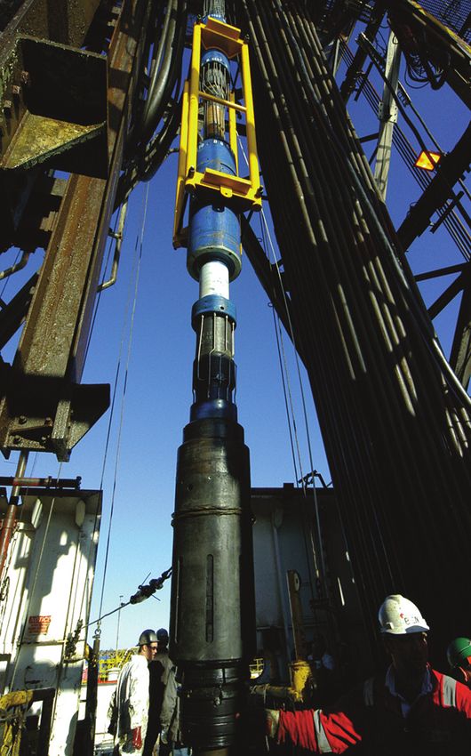
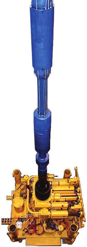
Subsea Safety Systems

ELSA-LB (Large Bore)

Our landing string assemblies are designed for
direct hydraulic (DH) and electro hydraulic (EH)
completion and intervention applications and
interface with all mono-bore completions when
used in conjunction with horizontal and
conventional subsea production trees.

The ELSA – LB comprises of a full suite of valve assemblies. The
lubricator valve, retainer valve and subsea test tree provide a full
range of well intervention, pressure control functions and
disconnection capabilities for harsh completion installation,
workover or intervention operations.

 Applications:
 Completion installation, workover and intervention operations on
 horizontal subsea xmas trees from mobile offshore drilling units in water
 depths up to 10,000 ft (3048m)
 Drill stem testing, well clean up and extended appraisal operations
 requiring a large flow bore
 Specifically designed to operate in batch completion campaigns where
 minimal redress operations between runs are critical

 Benefits:
 Provides a dual primary subsea barrier between the well and surface
 during subsea operations
 Allows subsea well operations to be conducted under controlled
 conditions without having to function the BOP
 Disconnect function allows mobile offshore drilling unit (MODU) to
 unlatch and re-latch safely should environmental conditions dictate
 Independent ball closure allows a single cutting device to be selected
 System reliability and maintenance requirements virtually eliminating rig
 down time
 Electrical feed through to facilitate surface readout
 Can be run with either EXPRESS subsea control systems or direct
 hydraulic (DH)
 Facilitate injection of chemicals to production bore
 Pump through capability for well equalisation or bull heading

exprogroup.com
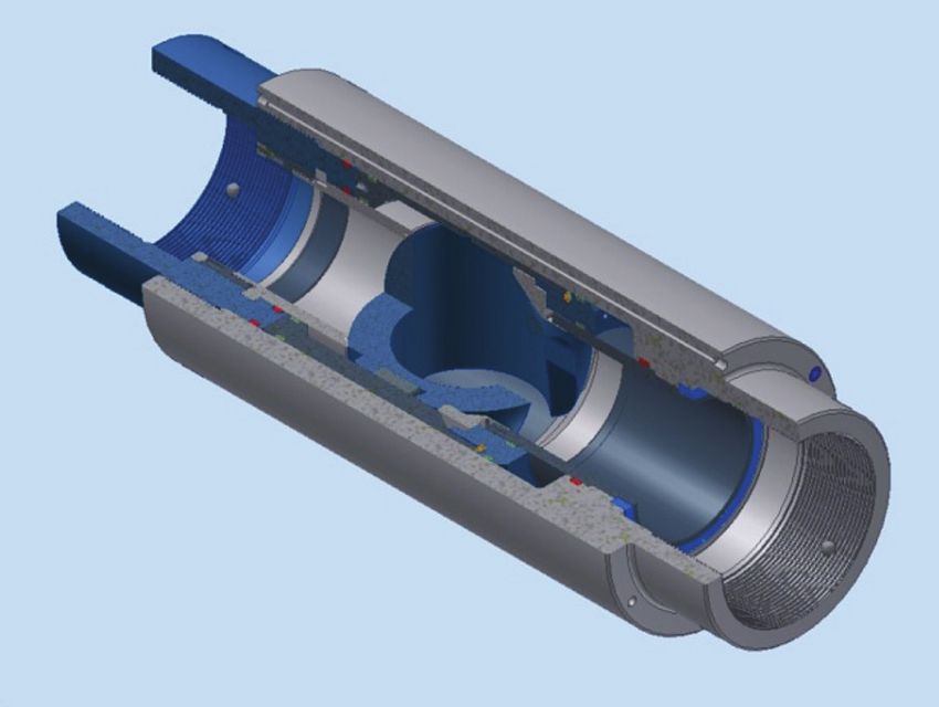
Subsea Safety Systems

ELSA-LB (Large Bore)

The Lubricator Valve

The lubricator valve (LV) forms an integral part of the subsea landing string for well test or intervention
operations and can be set at a pre-determined point below the rotary table or deepset in shallow
wells. It is the “work horse” within the production string isolating the well facilitating the introduction
of any through tubing tools.

The valve is of a ‘fail-as-is’ design. To cycle the
ball to the open position, control fluid is pumped
into the ball open line, displacing the
piston/mandrel assembly; the displaced fluid will
vent up the ball close line. The valve is closed by
pumping fluid into the ball close line and allowing
it to vent into the ball open line. For well isolation
purposes the LV is designed to hold a pressure
differential from below without further application
of control pressure. To hold pressure from above,
close control line pressure is applied to override
the pump through feature. It is possible to
equalise pressure across the valve by pumping
through before opening the ball or bull heading
the well whilst in the closed position. The pump
through pressure should not exceed the
maximum working pressure.

  Features:
  To facilitate the introduction of through tubing tools (i.e. coiled tubing and wireline) into the production string
  longer than those acceptable in a customary derrick installed lubricator assembly
  To provide a method of isolating surface equipment from the production flow
  To provide a means of pressure testing the surface equipment and lubricator sections once the wireline tool
  string has been installed
  Provides through port capability for either dual high set LV’s or downhole functionality when run deep set
  To allow the safe passage of an umbilical/s along its length (high-set option)
  To allow chemicals to be injected directly into the well stream through a dual sealing/backflow valve
  arrangement, with injection point below the ball
  To provide a pressure tight barrier between the well bore and BOP stack and/or marine riser
  Slickline cutting - optional

exprogroup.com
Subsea Safety Systems

ELSA-LB (Large Bore)

The Lubricator Valve

 Technical Specifications:

 Service                                               H2S NACE MR 0175 + CO2

 Maximum Working Pressure                              10,000 psi (690 bar)

 Test Pressure                                         15,000 psi (1,034 bar)

 Design Temperature                                    -18°C to 121°C (0°F to +250°F )

 Maximum Tensile Loading @ MWP                         Up to 400,000 lbs (1,779,288 N)

 Maximum Tensile Loading @ 0 psi / Bar                 1,000,000 lbs (4,448,220 N)

 Torsion Capacity                                      30,000 ft lbs (40,675 Nm)

 Pump Through Capability                               Yes

 Pressure Differential Support Facility   Above Ball   10,000 psi (690 bar)
                                          Below Ball   10,000 psi (690 bar)

 Overall Length                                        42.435 in (1078 mm)

 Outside Diameter (Max)                                15.260 in (4388 mm)

 Internal Diameter (Min)                               7.365 in (187 mm)

 Valve Failure mode                                    Fail-As-Is

 Hydraulic Control Working Pressure                    10,000 psi (690 Bar)

 Hydraulic Control Fluid Cleanliness                   Up to AS 4059 Class 6B through to F

 Chemical Injection Facility                           Injection below Ball

 Chemical Injection Working Pressure                   10,000 psi (690 bar)

 Weight Approximately                                  1235 lbs (560 kgs)

exprogroup.com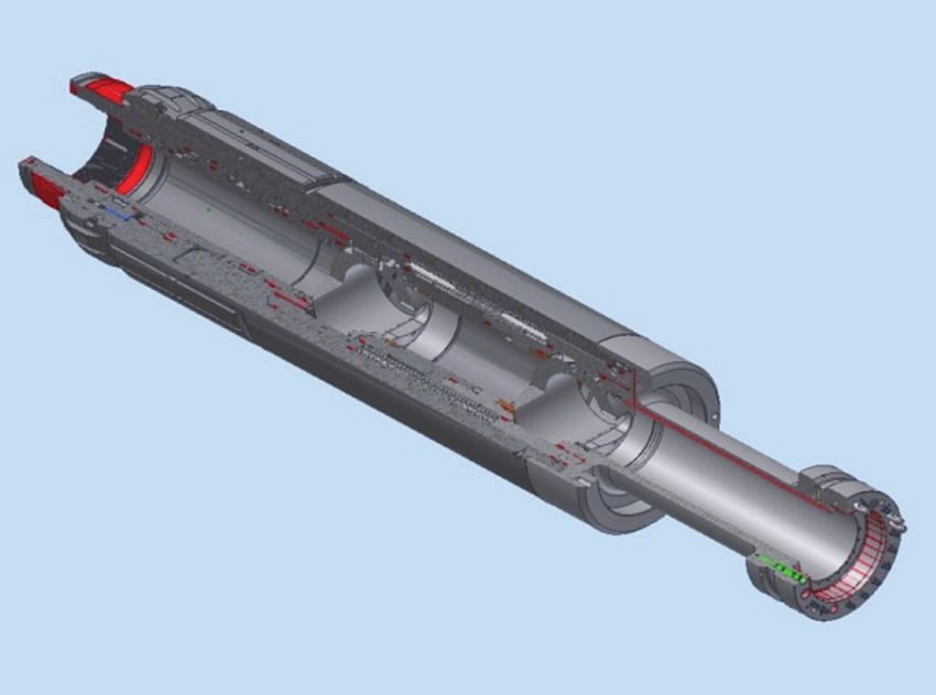
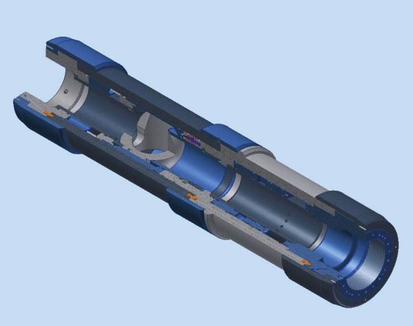
Subsea Safety Systems

ELSA-LB (Large Bore)

The Retainer Valve

The retainer valve (RV) forms an integral part of the subsea landing string for well test or intervention
operations. It is situated above the shear sub within the BOP stack. In the event of an emergency the
RV acts as an environmental valve reducing the spill of hydrocarbons into the environment.

The RV is configurable to be ‘failsafe close’ or ‘fail
as is’ and would be set up as per hazard and
operability study (HAZOP) requirements prior to
deployment. To cycle the ball to the open position,
control fluid is pumped into the ball open line,
displacing the piston/mandrel assembly; the
displaced fluid will vent up the ball close line. The
valve is either closed by pumping fluid into the ball
close line and allowing it to vent into the ball open
line or allowing the spring pack to close the
mechanism. Once the ball is in the fully closed
position an interlock (which can be disabled,
depending on the selected failure mode) is opened
allowing control fluid to move the vent sleeve into
the open position and equalise pressure between
production bore and marine riser. The vent sleeve is
cycled into the closed position before the ball valve
is opened again.

For well isolation purposes the valve is designed to
hold pressure differential from above only.

 Features:
 To retain the contents of the landing string above the ball after disconnection
 To vent the production bore pressure between the RV and the subsea test tree (SSTT) to the marine riser
 prior to disconnection of the SSTT
 To provide a slick diameter for the annular preventer to seal around (BOP spaceout dependant)
 To provide hydraulic interlock feature between the RV and SSTT latch assembly to ensure the RV has fully
 sequenced prior to disconnection (optional)
 To provide through porting capability for hydraulic control lines
 To provide a pressure tight barrier between the well bore and BOP stack
 To provide a bore large enough to accommodate plugs or tool strings specified by the customer
 Coil tubing cutting – (optional)

exprogroup.com
Subsea Safety Systems

ELSA-LB (Large Bore)

The Retainer Valve

 Technical Specifications:

 Service                                                  H2S NACE MR 0175 + CO2

 Maximum Working Pressure                                 10,000 psi (690 bar)

 Test Pressure                                            15,000 psi (1,034 bar)

 Design Temperature                                       -18°C to 121°C (0°F to +250°F )

 Maximum Tensile Loading @ MWP                            Up to 400,000 lbs (1,779,288 N)

 Maximum Tensile Loading @ 0 psi / Bar                    1,000,000 lbs (4,448,220 N)

 Torsion Capacity                                         30,000 ft lbs (40,675 Nm)

 Pump Through Capability                                  No Facility

 Pressure Differential Support Facility From Above Only   10,000 psi (690 bar)

 Overall Length (Shoulder to Shoulder)                    79.05 in (2008 mm)

 Outside Diameter (Max)                                   17.625 in (448 mm)

 Production Bore Internal Diameter (Min)                  7.365 in (187 mm)

 Valve Failure mode                                       Fail-Safe-Close or Fail as Is

 Hydraulic Control Working Pressure                       10,000 psi (690 bar)

 Hydraulic Control Fluid Cleanliness                      Up to AS 4059 Class 6B through to F

 Through Bore Hydraulic Lines                             Up to 18

 Weight Approximately                                     3649 lbs (1655 kgs)

exprogroup.com
Subsea Safety Systems

ELSA-LB (Large Bore) – DH Mode Only

The Subsea Test Tree

The subsea test tree (SSTT) forms an integral part of the subsea landing
string for well test or intervention operations, and mimics the functionality
of the blowout preventer (BOP) stack. It provides an operable primary
safety system to control tubing pressure with dual barrier isolation in the
event of an undesired situation or emergency.

The upper ball within the SSTT is capable of cutting wireline and/or coil tubing. The SSTT has a latch
arrangement which is capable of multiple unlatch/latch operations. The latch assembly also isolates
the hydraulics after disconnection and facilitates communication upon reconnection. Should all
hydraulic pressure be lost downhole then a secondary disconnect can be performed with the
application of pressure below the closed annular element. To open either valve, hydraulic pressure
is applied to the open side of the actuation piston which compresses the spring pack, and an offset
camming pin arrangement rotates the ball to the open position. To close either valve the open
hydraulic pressure is vented to allow the spring pack to push the piston, which in turn closes the ball.
Inherent to the valve is an interlock with the retainer valve that ensures the well is isolated prior to
disconnection.

Functional redundancy can be provided via a secondary system that is activated independently from
the primary hydraulic circuit; pressure manipulation from surface through the choke / kill lines below
the BOP pipe rams will access a pre-arranged sequential set of shuttles that direct the pressure to the
desired function.

 Features:
 To provide a means to isolate the well
 To provide a means to disconnect safely from the well
 By being compact in size, thus facilitating the closure of the BOP pipe/shear rams
 To provide a connectable conduit for hydraulic control functions for the tree vendor and down hole functions
 To provide secondary methods for disconnection, closure and THRT disconnection
 To allow chemicals to be injected directly into the well stream through a dual sealing/backflow valve
 arrangement, with injection point between the balls
 To provide a pressure tight barrier between the well bore and BOP stack
 To provide a bore large enough to accommodate plugs or tool strings specified by the customer
 To facilitate the pressure testing of the landing string above the upper ball
 Latch retrieval tool profile (LRT) – optional

exprogroup.com
Subsea Safety Systems

ELSA-LB (Large Bore) – DH Mode

The Subsea Test Tree

 Technical Specifications:

 Service                                                                H2S NACE MR 0175 + CO2

 Maximum Working Pressure                                               10,000 psi (690 bar)

 Test Pressure                                                          15,000 psi (1,034 bar)

 Design Temperature                                                     -18°C to 121°C (0°F to +250°F )

 Maximum Tensile Loading @ MWP                                          Up to 400,000 lbs (1,779,288 N)

 Maximum Tensile Loading @ 0 psi / Bar                                  1,000,000 lbs (4,448,220 N)

 Torsion Capacity                                                       30,000 ft lbs (40,675 Nm)

 Pump Through Capability                                                Yes

 Pressure Differential Support Facility         Above Upper Ball Only   4,000 psi (276 bar)

                                                Below Ball Valves       10,000 psi (690 bar)

 Overall Length (Shoulder to Shoulder)                                  Up to 101.95 in (2590 mm) *Slick Joint
                                                                        Dependent

 Slick Joint Diameter (project dependant)                               9.625 in (245 mm)

 Outside Diameter (Maximum)                                             18.550 in (471 mm)

 Production Bore Internal Diameter (Minimum)                            7.365 in (187 mm) * Slick Joint Dependent

 Valve Failure mode                                                     Fail-Safe-Close

 Hydraulic Control Working Pressure             Open and Close          6,000 psi (414 bar)

 Hydraulic Control Fluid Cleanliness                                    Up to AS 4059 Class 6B through to F

 Through Bore Hydraulic Lines                                           10

 Through Bore Hydraulic Control Working Pressure                        10,000 psi (690 bar)

 Chemical Injection Facility                                            Injection Between Balls

 Chemical Injection Facility Working Pressure                           10,000 psi (690 bar)

 Coil Tubing Cutting Capability                                         ∅ 2.375 in x 0.203 in WT(80Kpsi yield) c/w
                                                                        0.438” Mono-conductor

 Weight Approximately                                                   3565 lbs (1629 kgs)

exprogroup.com
Subsea Safety Systems ELSA-LB (Large Bore) – EH Mode The Subsea Test Tree The subsea test tree (SSTT) forms an integral part of the subsea landing string for well test or intervention operations, and mimics the functionality of the BOP stack. It provides an operable primary safety system to control tubing pressure with dual barrier isolation in the event of an undesired situation or emergency. The SSTT can be deployed direct or electro hydraulically. The upper ball within the SSTT is capable of cutting wireline and/or coil tubing. The SSTT incorporates a disconnect / reconnect feature, which in conjunction with the Electro-Hydraulic controls will give the required disconnect criteria required whilst operating from a DP vessel. The SSTT has a high debris tolerant, high tensile latch arrangement, which is capable of multiple unlatch/latch operations. The latch assembly also isolates the hydraulics after disconnection and facilitates communication upon reconnection. Should all hydraulic pressure be lost downhole then a secondary disconnect can be performed with the application of pressure below the closed annular element. To open either valve, hydraulic pressure is applied to the open side of the actuation piston which compresses the spring pack, and an offset camming pin arrangement rotates the ball to the open position. To close either valve the open hydraulic pressure is vented to allow the spring pack to push the piston, which in turn closes the ball. Inherent to the valve is an interlock that ensures the well is isolated prior to disconnection. Functional redundancy can be provided via a secondary system that is activated independently from the primary hydraulic circuit; pressure manipulation from surface through the choke / kill lines below the BOP pipe rams will access a pre- arranged sequential set of shuttles that direct the pressure to the desired function. Features: To provide a means to isolate the well To provide a means to disconnect safely from the well By being compact in size, thus facilitating the closure of the BOP pipe/shear rams To provide a connectable conduit for hydraulic control functions for the tree vendor and down hole functions To provide secondary methods for disconnection, closure and THRT disconnection To allow chemicals to be injected directly into the well stream through a dual sealing/backflow valve arrangement, with injection points between the balls To provide a pressure tight barrier between the well bore and BOP stack To provide a bore large enough to accommodate plugs or tool strings specified by the customer To facilitate the pressure testing of the landing string above the upper ball Latch retrieval tool profile (LRT) exprogroup.com
Subsea Safety Systems

ELSA-LB (Large Bore) – EH Mode

The Subsea Test Tree

 Technical Specifications:

 Service                                                           H2S NACE MR 0175 + CO2

 Maximum Working Pressure                                          10,000 psi (690 bar)

 Test Pressure                                                     15,000 psi (1,034 bar)

 Design Temperature                                                -18 °C to 121 °C (0°F to +250°F )

 Maximum Tensile Loading @ MWP                                     Up to 400,000 lbs (1,779,288 N)

 Maximum Tensile Loading @ 0 psi / Bar                             1,000,000 lbs (4,448,220 N)

 Torsion Capacity                                                  30,000 ft lbs (40,675 Nm)

 Pump Through Capability                                           Yes

 Pressure Differential Support Facility    Above Upper Ball Only   4,000 psi (276 bar)

                                           Below Ball Valves       10,000 psi (690 bar)

 Overall Length (Shoulder to Shoulder)                             105 in (2667 mm) *Slick Joint Dependent

 Slick Joint Diameter(project dependant)                           9.625 in (245 mm)

 Outside Diameter (Maximum)                                        18.550 in (471 mm)

 Production Bore Internal Diameter (Minimum)                       7.365 in (187 mm) *Slick Joint Dependent

 Valve Failure mode                                                Fail-Safe-Close

 Hydraulic Control Working Pressure        Open and Close          6,000 psi (414 bar)

 Minimum Hydraulic Control Fluid Cleanliness                       Up to AS 4059 Class 6B through to F

 Through Bore Hydraulic Lines                                      10

 Through Bore Hydraulic Control Working Pressure                   10,000 psi (690 bar)

 Chemical Injection Facility                                       Injection Between Balls

 Chemical Injection Working Pressure                               10,000 psi (690 bar)

 Coil Tubing Cutting Capability                                    ∅ 2.375 in x 0.203 in WT(80Kpsi yield) c/w
                                                                   0.438” Mono-conductor

 Weight Approximately                                              4599 lbs (2086 kgs) inc. slickjoint

                                                                                                                © Expro International Group LTD
                                                                                                                  ELSA-LB (Large Bore) 071211_v1

exprogroup.com
You can also read