SECTION IV RULES 2019 Bench BG-4 - MSHA
←
→
Page content transcription
If your browser does not render page correctly, please read the page content below
SECTION IV
   2019
Bench BG-4
  RULES

2019 BENCH BG-4 CONTEST RULES

                                                            INDEX

                                                          Section IV

Title                                                                                                                  Page

Rules Governing 2019 Bench BG-4 Contest and
Interpretations of Discount Cards ...............................................................................1

Statements of Fact (Bench Contest) ............................................................................15

Identification of Parts ...................................................................................................21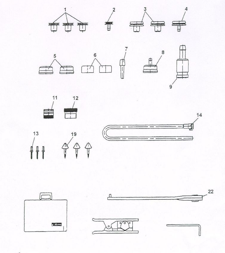
RULES GOVERNING 2019 BENCH BG-4 CONTEST
              AND INTERPRETATIONS OF DISCOUNT CARDS

1.   Each participant must be under guard before the start of the Contest in a
     location assigned by the Chief Judge and must remain continuously under
     guard until time to work the problem. Information for bench problem design is
     available on the MSHA website WWW.MSHA.Gov in the Mine Rescue section
     under BG4 Designers Resources. Participants under guard must be in a location
     where they will be unable to obtain any information concerning the problem to
     be worked. Any participant receiving information concerning a Contest
     problem prior to starting to work the problem will be disqualified by the Chief
     Judge and the Assistant Chief Judge. No person, except guards and Contest
     officials assigned to give the written examination, will be allowed to
     communicate with any participant under guard. Those who have performed
     will not be permitted to communicate with any participant awaiting their
     turn to perform.

2.   Any indication of receiving unauthorized information during the working of
     the problem may result in disqualification as determined by the Chief Judge
     and the Assistant Chief Judge. No one except judges, Contest officials, and
     working participants will be permitted in the work area, unless special
     approval is given by the Chief Judge. Communication with bench
     participants, except for the judges, is prohibited. News media and
     photographers who wish to be in the working area must receive permission
     from the Director and be accompanied by a Contest official.

3.   Any bench participant not in place and ready at the time specified will be
     disqualified from the Contest.

4.   The bench participant will be provided with two BG-4 apparatus (one
     disassembled, one assembled), an RZ-25 tester, RZ-7000 tester, or Test-It 6100, a
     stopwatch, defogging solution, leak detector fluid, test kit and a tool kit. Only
     the tools and fluid provided will be used for testing and assembly of the
     apparatus. The work at the bench will consist of (1) a visual examination of a
     disassembled BG-4 and the proper assembly and preparation for use in rescue
     work. This will include correcting any predetermined problem(s) so that the
     apparatus is in proper working order. Simulating defogging of the facepiece
     lens will be done as part of the visual examination. This visual examination,
     correcting predetermined problem(s), and proper assembly can be done at any
     time allowed for working of the problem. (2) Test the assembled BG-4
     apparatus with a tester, and correct the predetermined problem(s) so that the
     apparatus is in proper working condition. Except for removing the sealing cap
                                         1
from the coupling and removing the Cover shell, the assembled BG-4 apparatus
     cannot be disassembled to look for problems, until the hoses are attached to the
     tester and the apparatus fails a test. When testing is completed on the
     assembled BG-4 apparatus, the hoses shall be removed from the tester,
     connected to the facepiece, and the back cover installed. This shall be done
     before the clock is stopped.

5.   Spare parts to correct the predetermined problem(s) will be provided once
     the bench participant has specifically identified the problem. This will
     require the participant to point out the exact location of the deficiency.
     (Example: Positive pressure leak in the breathing bag. Participant will
     identify the location of the hole.)

6.   When an unplanned deficiency is encountered with the apparatus, the
     participant will be notified by the judges that the deficiency is not part of the
     problem. The judge will stop the clock, and any time used to correct the
     deficiency will not be charged to the working time. However, the process of
     verbal elimination shall not be used by the bench participant to find the
     predetermined problem(s). If it becomes obvious to the judges that this is
     occurring, the first offense will result in a warning, the second offense a
     discount, and the third offense could result in disqualification as determined by
     the Chief Judge. (Example: Participant verbally identifies a deficiency with
     every part of the facepiece when only one predetermined problem exists.)

7.   The bench participant will not be allowed to bring any materials, written
     information, or records to the work site. Tests will be performed in sequence on
     the assembled BG-4 apparatus using the standard test procedures with a tester
     as outlined in the Draeger Instruction for Use manual for PSS BG-4 AP/CP
     (Second Edition July 2004 or First Edition June 2007).

8.   A maximum of 30 minutes will be allowed to complete the problem. The
     bench judge will inform the participant when he/she has Five minutes
     remaining to work the problem. At the completion of the problem, the
     judge(s) and the participant will note the working time of the problem with
     the official timekeeper. Work done after the clock is stopped will not be
     recognized.

9.   Manually abusing or intentionally over or under pressurizing the tester
     substantially will be considered abusing the equipment. If the participant is
     observed abusing the tester, the first offense will result in a warning, the second
     offense will result in a discount, and the third offense could result in
     disqualification as determined by the Chief Judge.
                                          2
A. Written Examination of Bench Participant
1. The written examination shall consist of 30 questions. Twenty questions
for the written examination will be taken verbatim from the Statements
of Fact which will be multiple choice with three choices and each blank
shall represent a key word with no more than two consecutive blanks per
statement. Ten questions will be taken verbatim from identification of
parts. Intentional misspelling of words by the test developer will not be
allowed. Multiple choice answers with numbers will either be in the
form of numbers written out or numerical. Either version is acceptable.
“None of the above” is not acceptable as one of the answers. Thirty
minutes will be allowed for the written examination.
2. In special circumstances, individual bench participants may be given
oral instead of written examinations by at least two judges. Requests
for consideration shall be presented to the Director of the Contest at
the time of registration.
3. Bench participants will be separated to the extent possible, and every
effort will be made to prohibit discussion of questions and answers
among the bench participants.
B. Miscellaneous
1. In the event of ties in the Bench Contest, the number of discounts at
bench will be the first tie breaker; the number of discounts on written
examination will be the second tie breaker; and the official working
time at bench in minutes and seconds will be the third tie breaker.
2. The bench participant and trainer will report to a designated location to
review and prepare protests within one hour of notification. Twenty
minutes will be given to review and prepare written protests. All
protests will be considered by the Chief Judge and his/her Assistant
and their decision will be binding.
3. Disputes with regard to the Bench Contest (except discounts), shall be
immediately filed with the Director. Disputes filed shall be in writing and
set forth incidents, times, names, source of information and act
complained against. Complainant shall remain accessible to the Director
until the complaint is resolved. A decision by the Director shall be final.
34. Any similar terminology used to describe a part is acceptable such as;
cylinder or bottle, etc.
5. Bench participants must be bonafide employees of the mining
industry or members of mine rescue teams designated to fulfill the
requirements of 30 CFR Part 49. This does not exclude bench
participants whose team is not participating at the National Contest
or a member of a college mine rescue team.
6. All parts must correspond with the individual units that are being
used for contest purposes only. (Drain valve, cooler, mask, anti-vibe,
CO2 absorber, hoses, coupler, etc.)
Interpretations of Discount Sheet
A. Written Examination
1. For each incorrect statement 1
B. Time
The time will be recorded in minutes and seconds.
C. Competition at Bench
1. Failure to verbally identify each test being conducted 2
Verbally identify each test being performed.
2. Failure to verbally identify each problem 5
Failure to verbally identify is also interpreted as failure to find the
problem.
3. Failure to correct each problem 5
The bench participant shall properly correct the problem and continue
with the proper tests. Once a bench participant finds a predetermined
4problem and does not correct it before continuing with the remaining
tests, he/she shall receive a five point discount for continuing without
correcting the problem and a pending five point discount for failing to
correct the problem. If all of the remaining tests are properly conducted
and passed and the participant returns to the uncorrected problem and
corrects it, the pending five point discount will not be assessed. Should
the participant continue on from this point and properly conduct all of
the remaining tests again, he/she would also have the original five point
discount for continuing tests removed.
4. Failure to conduct any visual examination or test on the BG-4, each test
5
5. Failure to tighten connections properly during assembly or testing,
each connection 1
All connections must be tightened on the apparatus and verbally
identified as hand tight at the time the connection is made. Failure to
verbally identify at the time the connection is being made will result in a
one point discount for each. Zero adjustments shall be made on the
tester prior to connecting the breathing hoses to the tester.
This includes:
Cap on drain valve - hand tight
Drain valve to breathing bag - hand tight
Minimum valve to breathing bag - hand tight
Minimum valve to O2 supply hose- hand tight
Cylinder connection - hand tight
Factory/Refillable Cartridge connections - hand tight
Relief valve connection - hand tight
Cooler to bag connection - hand tight
Distribution hose connection - hand tight
Breathing hoses during the visual examination on the disassembled
apparatus) – Hand
Hose adapter on the tester - hand tight
Cross over Hose to Switchbox and Relief valve – hand tight
Once the zero adjustment on the tester has been made, do not readjust
setting for balance of tests.
6. Failure to comply with rules not covered in discount sheet, each
infraction 2
5If the discount is not listed on the discount sheet, and if it is not
covered under one of the approved rules of the Contest, do not
improvise a discount to cover the suspected violation.
D. Visuals
1. Failure to conduct a proper visual examination of the
frame/harness 1
The visual examination will include an examination of the harness
assembly, frame, back cover, visible sealing rings, Sentinel, O2
regulator, Anti-vibe and switch box.
Failure to examine and verbally identify the examination will result in
one discount for each. (Maximum 4 points)
2. Failure to conduct a proper visual examination of the breathing
bag 1
The participant will verbally identify that the breathing bag is being
examined for pliability and signs of deterioration. Stretching or
manipulating the breathing bag with a massaging action will be part of
this examination. The participant will verbally identify that the sealing
surfaces are being examined for signs of deterioration or damage.
Also, the minimum valve, drain valve, lever, and springs will be
examined for damage. Failure to examine and verbally identify the
examination will result in one discount for each. (Maximum 4 points)
3. Failure to conduct a proper visual examination of the O2
Cylinder 1
A proper cylinder examination includes a visual inspection of the
cylinder. The participant will verbally identify the cylinder pressure on
the gauge, the pressure rating on cylinder, the latest hydrostatic test
date, and identify if the cylinder is plus rated, if steel. Participant will
inform the judge if the cylinder pressure is less than 2,600 PSI for the
Sentinel. Failure to examine and verbally identify the examination will
result in one discount for each. (Maximum 4 points)
4. Failure to conduct a proper visual examination of the
Factory/refillable Cartridge 1
6A proper examination includes a visual inspection for defects. If a
Factory packed cartridge is used, verbally identify that the sealing
surfaces are not damaged, and identify the expiration date with month
and year. If a refillable cartridge is used, a visual inspection for defects,
strap with tension spring hook, seal, Refillable scrubber screens and filter
mats are required. Failure to examine and verbally identify the
examination will result in one discount for each. (Maximum 3 points)
5. Failure to conduct a proper visual examination of the relief valve 1
A proper examination includes a visual inspection for defects. Verbally
identify that the valve and O-ring are not damaged.
6. Failure to conduct a proper visual examination of the cooler 1
A proper examination includes a visual inspection for defects.
Verbally identify that the sealing surfaces are not damaged.
7. Failure to conduct a proper visual examination of the hoses 1
The participant will verbally identify that the hoses are being inspected
for pliability and signs of deterioration. Stretching or manipulating the
hoses with a massaging action will be part of this examination. The
participant will verbally identify that the sealing edges/surfaces,
including bayonet rings and Anti-crush rings are being examined for
signs of deterioration. Failure to examine and verbally identify the
examination will result in one discount for each. (Maximum 2 points)
8. Failure to conduct a proper visual examination of the coupling,
inhalation and exhalation valves 1
A proper examination includes a visual inspection for defects, sealing
surfaces and valve discs. Verbally identify that the sealing
edges/surfaces and valve discs are not damaged.
9. Failure to conduct a proper visual examination of the facepiece 1
The visual examination will include an examination of the head strap
assembly, mask body (including sealing surfaces), the lens visor,
speaking diaphragm, and wiper. Defogging the lens visor shall be
simulated as part of the visual facepiece examination. Failure to
examine and verbally identify the examination will result in one
discount for each. (Maximum 4 points)
710. Failure to have Visual Apparatus fully assembled.
(Ready for use) 2
E. RZ-25 Tester
1. Failure to conduct a proper low pressure warning test 2
Connect breathing hoses to test unit. Set RZ-25 tester on positive
pressure pumping, gently activate bellows, and watch the pressure
gauge. If the low pressure warning is operating properly, warning
should be activated when the pressure is less than 1.4 mbar for the
Sentinel.
2. Failure to conduct a proper inhalation valve test 2
The RZ-25 tester is set on positive pressure pumping. Tightly pinch the
exhalation hose with your hand. Gently activate bellows until 10 mbar
is indicated on the pressure gauge.
3. Failure to conduct a proper exhalation valve test 2
Set the RZ-25 tester on negative pressure pumping. Tightly pinch the
inhalation hose with your hand. Gently activate bellows until -10 mbar
is indicated on the pressure gauge.
4. Failure to conduct a proper drain valve test 2
Set RZ-25 tester on positive pressure pumping. Pump bellows until 10
mbar is indicated on the pressure gauge. While pumping, fit the open
side of the sealing cap over the tappet of the relief valve and hold it
tightly until it is pressed into place by the inflated breathing bag. The
drain valve must not open at 10 mbar.
5. Failure to conduct a proper leak test with positive pressure 2
Set RZ-tester on leak test. Bleed needle to 7 mbar and start stopwatch.
Needle should not change more than 10 mm H20 or 1 mbar in 60
seconds. Set RZ-tester on negative pressure pumping, the breathing bag
is vented. Remove the sealing cap.
6. Failure to conduct a proper relief valve test 2
8Set RZ-tester on positive pressure pumping. Pump the bellows until
the relief valve opens, it should open between 2 and 5 mbar.
Participant will verbally state reading of valve opening.
NOTE: An alternate relief valve test may be conducted by observing
the reading on the RZ tester (with the tester set on leak test). Flow of
oxygen from the constant dosage will cause relief valve to open
between 2 and 5 mbar. If this alternate test is used, it must be
conducted after the completion of the bypass valve test.
7. Failure to conduct a proper high pressure leak test 2
Set RZ-25 tester on leak test. Open cylinder valve. Watch the Sentinel
unit, the cylinder pressure is indicated here. If it is lower than 2600 psi,
change the oxygen cylinder. If it is greater than 2600 psi, alarm beeps
two times. Sentinel indicates “close cylinder” icon, as soon as the icon
appears, close cylinder valve.
Result of the tests is output after approximately 15 seconds.
If the PSS BG-4 is okay, “open cylinder valve” icon, as soon as
the icon appears open cylinder valve.
8. Failure to conduct a proper constant metering valve test 2
Set RZ-25 tester on positive pressure pumping. Pump bellows until the
breathing bag is inflated. While pumping, fit the open side of the sealing
cap over the tappet of the relief valve and hold it tightly until it is
pressed into position by the inflated bag. Set the RZ-tester on Red
Dosage 0.5 - 2 L/min. The constant metering quantity should lie
between 1.5 and 1.9 L/min. Participant will verbally state dosage value
on the red scale as soon as the pointer has stopped moving.
9. Failure to conduct a proper minimum valve test 2
Set RZ-25 tester on negative pressure pumping. The breathing bag is
vented automatically, remove sealing cap, pump bellows until minimum
valve is heard to open in breathing bag and there is a hissing sound.
Watch the pressure gauge, the minimum valve should open at a value
between 0.1 and 2.5 mbar. Participant will verbally identify reading of
opening of valve.
10. Failure to conduct a proper bypass valve test 2
9Set RZ-tester on leak test. Press red button for bypass valve. Oxygen
must be heard to flow into the circuit, the breathing bag inflates.
11. Failure to conduct a proper low/residual pressure warning
test 2
Close cylinder valve. Watch the display or sentinel unit. The warning
should be generated at approx. 700 psi. Alarm sounds intermittently,
red indicator flashes. Unplug coupling from RZ-tester. Participant will
verbally state reading.
12. Failure to conduct a proper battery test 2
On activation and deactivation, the Sentinel automatically checks and
displays the battery capacity. To switch off the Sentinel, simultaneously
press the right and left hand button until the single sharp audible bleep
sounds. Release the buttons. For three seconds, Sentinel shows the
battery status. Sentinel switches off.
13. Failure to have Test Apparatus fully assembled. (Ready for use)
2
F. RZ-7000 Tester
1. Failure to conduct a proper low pressure warning test 2
Connect breathing hoses to test unit. Set RZ-7000 tester on positive
pressure pumping, gently pump, and watch the pressure gauge. If
the low pressure warning is operating properly, warning should be
activated when the pressure is less than 1.4 mbar for the Sentinel.
2. Failure to conduct a proper inhalation valve test 2
The RZ-7000 tester is set on positive pressure pumping. Tightly pinch
the exhalation hose with your hand. Pump until 10 mbar is indicated
on the pressure gauge.
3. Failure to conduct a proper exhalation valve test 2
Set the RZ-7000 tester on negative pressure pumping. Tightly pinch the
inhalation hose with your hand. Pump until -10 mbar is indicated on
the pressure gauge.
104. Failure to conduct a proper drain valve test 2
Set RZ-7000 tester on positive pressure pumping. Pump until 15 mbar is
indicated on the pressure gauge. While pumping, fit the open side of the
sealing cap over the tappet of the relief valve and hold it tightly until it is
pressed into place by the inflated breathing bag. The drain valve should
not open before 15mbar.
5. Failure to conduct a proper leak test with positive pressure 2
Set RZ-7000 tester on leak test. Bleed needle to 7.5 mbar and start
stopwatch. Needle should not change more than 10 mm H20 or 1 mbar
in 60 seconds. Set RZ-7000 tester on negative pressure pumping, the
breathing bag is vented. Remove the sealing cap.
6. Failure to conduct a proper relief valve test 2
Set RZ-7000 tester on positive pressure pumping. Pump until the relief
valve opens, it should open between 2 and 5 mbar. Participant will
verbally state reading of valve opening.
NOTE: An alternate relief valve test may be conducted by observing
the reading on the RZ-7000 tester (with the tester set on leak test).
Flow of oxygen from the constant dosage will cause relief valve to
open between 2 and 5 mbar. If this alternate test is used, it must be
conducted after the completion of the bypass valve test.
7. Failure to conduct a proper high pressure leak test 2
Set RZ-7000 tester on leak test. Open cylinder valve. Watch the Sentinel
unit, the cylinder pressure is indicated here. If it is lower than 2600 psi,
change the oxygen cylinder. If it is greater than 2600 psi, alarm beeps
two times. Sentinel indicates “close cylinder” icon, as soon as the icon
appears, close cylinder valve.
Result of the tests is output after approximately 15 seconds.
If the PSS BG-4 is okay, “open cylinder valve” icon, as soon as
the icon appears open cylinder valve.
8. Failure to conduct a proper constant metering valve test 2
Set RZ-7000 tester on positive pressure pumping. Pump until the
breathing bag is inflated. While pumping, fit the open side of the sealing
11cap over the tappet of the relief valve and hold it tightly until it is
pressed into position by the inflated bag. Set the RZ-7000 tester on Red
Dosage 0.5 - 2 L/min. The constant metering quantity should lie
between 1.5 and 1.9 L/min. Participant will verbally state dosage value
on the red scale as soon as the pointer has stopped moving.
9. Failure to conduct a proper minimum valve test 2
Set RZ-7000 tester on negative pressure pumping. The breathing bag is
vented automatically, remove sealing cap, pump until minimum valve is
heard to open in breathing bag and there is a hissing sound. Watch the
pressure gauge, the minimum valve should open at a value between 0.1
and 2.5 mbar. Participant will verbally identify reading of opening of
valve.
10. Failure to conduct a proper bypass valve test 2
Set RZ-7000 tester on leak test. Press red button for bypass valve.
Oxygen must be heard to flow into the circuit, the breathing bag
inflates.
11. Failure to conduct a proper low/residual pressure warning
test 2
Close cylinder valve. Watch the display or sentinel unit. The warning
should be generated at approx. 700 psi. Alarm sounds intermittently,
red indicator flashes. Unplug coupling from RZ-7000 tester. Participant
will verbally state reading.
12. Failure to conduct a proper battery test 2
On activation and deactivation, the Sentinel automatically checks and
displays the battery capacity. To switch off the Sentinel, simultaneously
press the right and left hand button until the single sharp audible bleep
sounds. Release the buttons. For three seconds, Sentinel shows the
battery status. Sentinel switches off.
13. Failure to have Test Apparatus fully assembled. (Ready for use)
2
G. Test-It 6100
1. Failure to conduct a proper low pressure warning test 2
12Connect breathing hoses to the tester. Set Test-It 6100 so that it
indicates the pressure in mbar. Open shut-off valve at the test unit.
Connect positive pressure side of the pump to the test unit. Pump
slowly. Watch the test unit; the low pressure warning should be
activated when the pressure is lower than 1.4 mbar for the Sentinel.
De-aerate PSS BG 4 via test unit until the low pressure warning is
switched off.
2. Failure to conduct a proper inhalation valve test 2
The tester is set on pressure in mbar. Connect positive pressure side
of the pump to the test unit. Tightly pinch the exhalation hose with
your hand. Pump slowly until at least 10 mbar is indicated on the test
unit.
3. Failure to conduct a proper exhalation valve test 2
The tester is set on pressure in mbar. Connect negative pressure side
of the pump to the test unit. Tightly pinch the inhalation hose with
your hand. Gently activate pump until at least -10 mbar is indicated
on the test unit.
4. Failure to conduct a proper drain valve test 2
Connect positive pressure side of the pump to the test unit. Pump
until at least 10 mbar is indicated on the pressure gauge. While
pumping, fit the open side of the sealing cap over the tappet of the
relief valve and hold it tightly until it is pressed into place by the
inflated breathing bag. The drain valve should not open before 15
mbar.
5. Failure to conduct a proper leak test with positive pressure 2
Close shut-off valve at the test unit. Reduce the pressure to 7 mbar at
the test unit. Start the stopwatch. Reading should not change by more
than 1 mbar in 60 seconds. Open the shut-off valve and De-aerate PSS
BG 4. Remove the sealing cap.
6. Failure to conduct a proper relief valve test 2
Open shut-off valve at the test unit. Connect positive pressure side of
13the pump to the test unit. Pump slowly until the relief valve opens; it
should open between 2 and 5 mbar. Participant will verbally state
reading of valve opening.
7. Failure to conduct a proper high pressure leak test 2
Set tester on leak test. Open cylinder valve. Watch the display unit, the
cylinder pressure is indicated here. If it is lower than 2600 psi, change the
oxygen cylinder. If it is greater than 2600 psi, alarm sounds once.
Sentinel indicates “close cylinder” icon, as soon as the icon appears, close
cylinder valve.
Result of the tests is output after approximately 15 seconds.
If the PSS BG-4 is okay, “open cylinder valve” icon, as soon as the icon
appears open the cylinder valve.
8. Failure to conduct a proper constant metering valve test 2
Open the flow valve, switch Test-It 6100 to LPM, install dosage adapter
and gently activate bypass valve to seat sealing cap over relief valve to
reach 1.5 LPM. The constant metering quantity should lie between 1.5
and 1.9 L/min. Participant will verbally state dosage value on the red
scale, as soon as the pointer has stopped moving.
9. Failure to conduct a proper minimum valve test 2
Set the tester to indicate pressure and negative pressure pumping. The
breathing bag is vented automatically, remove sealing cap, pump with
negative pressure until minimum valve is heard to open in breathing bag
and there is a hissing sound. Watch the display, the minimum valve
should open at a value between 0.1 and 2.5 mbar. Participant will
verbally identify reading of opening of valve.
10. Failure to conduct a proper bypass valve test 2
Close the shut-off valve at the test unit. Press red button for bypass
valve. Oxygen must be heard to flow into the circuit, the breathing bag
inflates.
11. Failure to conduct a proper low/residual pressure warning
test 2
14Close cylinder valve. Watch the display or sentinel unit. The warning
should be generated at approximately 700 psi. Alarm sounds
intermittently, red indicator flashes. Unplug coupling from tester.
Participant will verbally state reading.
12. Failure to conduct a proper battery test 2
On activation and deactivation, the Sentinel automatically checks and
displays the battery capacity. To switch off the Sentinel, simultaneously
press the right and left hand button until the single sharp audible bleep
sounds. Release the buttons. For three seconds, Sentinel shows the
battery status. Sentinel switches off.
13. Failure to have Test Apparatus fully assembled. (Ready for use)Note:
Breathing hoses do not need to be in straps on test apparatus
2
15STATEMENTS OF FACT
BENCH BG-4 CONTEST
1. A positive pressure leak could be caused by a leakage in or at device
components.
2. The battery in the Sentinel should be replaced every 6 months.
3. Dow Corning 111 is to be used to lubricate O-rings.
4. The pressure relief valve is designed to open when the pressure within the
breathing circuit is between +20 and +50 millimeters (+2 mbar and +5 mbar) of
pressure measured on the water gage.
5. To prepare for testing adjust zero point of the RZ-25 tester.
6. Test adapter is used to connect the BG-4 apparatus to the RZ-25 tester.
7. A leaky exhalation or inhalation valve could be caused by a defective valve
seat or valve disc.
8. During the exhalation valve test, if valve is operating properly, -10 mbar is
indicated on the pressure gauge.
9. The EPDM breathing hoses use Bayonet Rings.
10. During testing of the inhalation valve, if valve is operating properly, +10
mbar is indicated on the pressure gauge.
11. During the positive pressure leak test, the pressure change within 1 minute
must be lower than 1 mbar.
12. Only DRAGERSORB 400 is to be used to fill the refillable cartridge.
13. The factory packed cartridge is good for 4 years from the manufacture date.
14. A positive pressure in the breathing circuit prevents ambient air from
entering the system.
15. The BG-4 is approved with a factory/refillable cartridge.
16. The Sentinel monitoring system comprises a sensor unit, switchbox, and
Sentinel.
17. A steel cylinder is full at 3135 psi when a + is stamped at hydro test.
18. The BG-4 constant dosage must be 1.5 to 1.9 L/min.
1619. The drain valve should not open at less than 10 mbar.
20. A fully filled steel oxygen cylinder holds 440 liters of medical oxygen.
21. The accuracy of the Sentinel pressure measurement is +or- 2% of the final
value.
22. Never replace the battery in potentially explosive areas.
23. The weight of a fully charged BG-4 apparatus is 15kg (33 lbs)
24. Check the supply of oxygen gas on the Sentinel at intervals of
approximately 15 minutes.
25. During the constant dosage test, the breathing bag is inflated, the RZ-25 tester is
set to red dosage, and the pressure relief valve is capped.
26. During the constant dosage test, the needle of the RZ-25 tester should
automatically settle between 1.5 and 1.9 LPM.
27. The minimum valve provides greater than 80 L/min flow.
28. The breathing bag has a 5.5 liter volume.
29. Insert speech diaphragm, install retainer ring and tighten with spanner.
30. The belt and harness must be dried prior to storage, to prevent growth of
mold and fungus.
31. The pressure reducer must be rebuilt/over-hauled every 6 years.
32. Symbol X with error code indicates a failed self-check.
33. The Sentinel converts pressure into digital signal.
34. The cylinder connector and cylinder valve must not be contaminated with oil
or grease.
35. Three hexagon socket head screws are used in the battery cover of the
Sentinel.
36. Rubber parts must be particularly protected from direct exposure to
radiation.
37. Do not use any solvents, such as acetone, alcohol, benzene, white spirit,
17trichloroethylene, etc. for cleaning rubber and silicone parts.
38. The first low pressure warning occurs when the pressure drops to
approximately 700 psi.
39. At the first low pressure warning approximately 75% of the oxygen has been
used up.
40. The last low pressure warning occurs when the pressure drops to
approximately 145 psi.
41. During the low pressure warning test, the alarm should activate at
approximately 700 PSI for a 4 hour apparatus.
42. At the last low pressure warning approximately 95% of the oxygen has been
used up.
43. To start the main alarm, press the Yellow panic button in center of the
Sentinel.
44. When the first low pressure warning occurs, the alarm sounds intermittently for
approximately 30 seconds and the red LED flashes constantly.
45. When the last low pressure warning occurs, the alarm sounds intermittently
without stopping and the red LED flashes constantly.
46. Medium pressure in the BG-4 is between 58 psi and 64 psi.
47. Medium pressure is delivered to the minimum valve.
48. The drain valve opens at more than 10 mbar.
49. The BG-4 breathing circuit is designed with an air cooler that can be filled
with ice to reduce the temperature of the inhaled breath.
50 Remove the Tally Key to activate the motion sensor.
51. The venting hole located in the Cover for cooler must point upwards.
52. All parts which come in contact with the exhaled air must be thoroughly
cleaned and disinfected after use.
53. Disinfect parts by immersing them in a disinfectant bath using Airkem 33.
54. Before washing the minimum valve, it is necessary to isolate the minimum valve
with plug.
1855. Attach minimum valve to breathing bag so that the pin of the
minimum valve and the mark on the breathing bag line up.
56. All parts which have been disinfected should be rinsed thoroughly under
running water.
57. C O2 absorber is not approved for use after indicated expiration date.
58. The maximum temperature of the air used to dry parts should not go above
60 degree C (140 degree F).
59. Replace the high pressure O-ring located on the pressure reducer yearly for
units which are in constant use.
60. U.S. D.O.T. hydro test composite cylinders every 5 years.
61. Replace the O-ring at the plug-in coupling at least once every year for units
which are in constant use.
62. The inhalation/exhalation valve should be replaced every 3 years for units
which are in constant use.
63. The O-ring under the speech diaphragm should be lubricated with Dow
Corning 111.
64. The pressure reducer should be returned to the manufacturer or their agent
for complete overhaul after at least 6 years usage.
65. A steel oxygen cylinder must be retested by a certified testing facility every 5
years.
66. The BG-4 is approved for use at temperatures above -5 degree C (23 degree F)
67. A defective pressure reducer should be returned to the manufacturer or their
agent for service as needed.
68. Only oxygen (medical grade or better) with > 99.5% purity is to be used to fill
the BG-4 oxygen cylinders.
69. The use of ice in the cooling system is only required at ambient temperature
above 0 degree C (32 degree F).
70. Pressurized oxygen in contact with oil, grease, or other contamination can
result in fire or explosion.
71. It is safe to use the BG 4 for up to 4 hours with a battery warning 1 Icon.
1972. The battery must be replaced if battery warning 2 Icon is indicated.
73. A defective pressure reducer is the probable cause if the manual by-pass
valve does not blow-off.
74. The green LED flashes to indicate that the Sentinel is operating normally.
75. Bypass output is > 50 L/min.
76. Relief valve activation is 6 bar or (87 psi).
77. The oxygen cylinder Burst disc ruptures at 4,000 psi (275 bar).
78. Refillable cartridge concerns are over packing and under packing.
79. The EPDM and silicone masks allow 90% peripheral vision.
80. Polycarbonate or Plexiglas lenses can be used in the mask.
81. A minimum of 2600 psi is needed for a Sentinel to perform a proper high
pressure leak test.
82. The drain valve opens at approximately 15 mbar and is therefore out of the
RZ reading range.
83. To prepare the ice pack:
Fill the ice receptacle with water up to 2 inches from rim
Freeze at least 16 hours @ -15 degree C (5 degree F)
Fill to rim with water
Freeze again for another 8 hours
84. If the speech diaphragm is deformed or shows signs of damage, it must be
replaced.
85. The BG-4 Sentinel lights up when the button is briefly pressed.
86. Press then release the right hand button to display temperature.
87. Do not re-use Factory cartridges.
88. The breathing hoses are equipped with anti-crush rings.
89. When conducting component checks use a test pressure between +7 mbar and
+10 mbar with a max pressure loss of 1 mbar/min.
2090. Only the following batteries are approved for use in the Sentinel:
Rayovac
Eveready
Panasonic
Ultra-life Lithium
21BG-4
1 2 1 2
Cons. No. Designation Cons. No. Designation
1 Carrying Housing 12 Breathing Bag
2 Cover Shell , complete 15 Lever, Complete
3 Shoulder Pad Assembly 16 Factory/refillable cartridge
5 Cooler 17 Pressure Reducer BG4
6 Relief valve, Complete 19 Oxygen Cylinder
7 Minimum Valve 21 Distribution Hose
8 Drain Valve 22 Panorama Nova Mask
9 Sentinel FPS 7000 Mask
10 Switch Box
11 Pressure Sensor
22Cover
1 2 1 2
Cons. No. Designation Cons. No. Designation
1 Cover Shell 3 Grip Cap
2 Hinge 4 Button
23Harness Assembly
1 2 1 2
Cons. No. Designation Cons. No. Designation
1 Shoulder Pad Assembly 5 Adjusting Belt Assembly
2 Shoulder Adjusting Strap 6 Waist belt
3 Hose Clip 7 Belt Assembly
4 Hose Strap Harness 8 Buckle
24Breathing Hose Assembly
1 2 1 2
Cons. No. Designation Cons. No. Designation
1 Coupling 6 Bayonet Ring
2 Inhalation Valve Seat 7 Anti-Crush rings
3 Exhalation Valve Seat 8 Toroidal Sealing Ring
4 Valve Disc 9 Sealing Cap
5 Corrugated Hose
25Cooling Canister
1 2 1 2
Cons. No. Designation Cons. No. Designation
1 Cooler 4 Angle Connector
2 Cover for Cooler 5 Reaction Ring
3 Gasket
26Drain/Relief/Minimum Valve Assembly
1 2 1 2
Cons. No. Designation Cons. No. Designation
1 Valve Disc 12 Cap
2 Crater Case 15 Valve Crater
3 Valve Disc 16 Washer
4 Relief / Drain Valve Spring 18 Valve Plate
5 O-Ring 19 Spring
7 Clamp Fitting 22 Clamp, Minimum Valve
8 Hose 23 Angle Connecter
9 Coupling
10 O-Ring
27Sentinel
1 2 1 2
Cons. No. Designation Cons. No. Designation
1 Sentinel 8 Copper Ring
2 Switch Box 9 9 volt battery
3 Angle Connector 13 Tally Key
7 Pressure Sensor
28Refillable Cartridge
1 2 1 2
Cons. No. Designation Cons. No. Designation
5 Refillable Scrubber Screen
1-8 Refillable Cartridge 6 Filter Mats
2 Lid 8 NIOSH Approval Label
3 Seal, Refillable Cartridge
4 Strap with Tension Spring Hook
29FPS 7000 Mask
1 2 1 2
Cons. No. Designation Cons. No. Designation
1 Mask Body FPS 7000 13 Inner Mask
2 Upper Visor Frame 14 Button
3 Visor 15A Head Strap
4 Lower Visor Frame 15B Hairnet
7 Clamp 16 Sliding Buckle
8 Connector Piece 17 Double Button
9 Cover 18 Neck Strap
11 Turning Knob
12 Disc
30Oxygen Cylinder
1 2 1 2
Cons. No. Designation Cons. No. Designation
3 Valve Housing 18 Lock Washer
10 Hand-wheel 19 Lock Nut
13 Safety Ring 20 Bursting Disc
16 Sealing Ring 21 Oxygen Cylinder
17 Manometer 22 Label
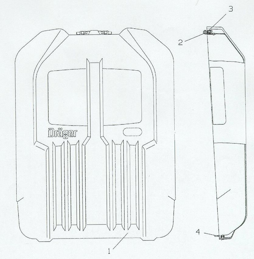
31Test Kit
1 2 1 2
Cons. No. Designation Cons. No. Designation
1 Plug For Breathing Bag 11 Sealing Plug for Mask
2 Nozzle For Breathing Bag 12 Test Adaptor
3 Sealing Plug (Corrugated Hose) 13 Sealing Plug for Plug In Conn.
4 Test Socket for Corrugated Hose 14 Test Hose/Metering Control
5 Sealing Cap for Corrugated Hose 19 Sealing Ring Lifters
6 Sealing Cap 22 Spanner
7 Testing Plug
8 Test Cap for Corrugated Hose
9 Test Connection for Control Valve
32You can also read