Dival SQD-1 Pressure Regulators - TECHNICAL MANUAL - Pietro Fiorentini
←
→
Page content transcription
If your browser does not render page correctly, please read the page content below
Pressure Regulators

Dival SQD-1

    TECHNICAL MANUAL
    INSTALLATION ,COMMISSIONING
    AND MAINTENANCE ISTRUCTIONS

                                  EN
Poster                                       EN

                                   Dival SQD-1

              Inlet pressure
              Outlet pressure

Dival SQD-1 - MT 234-E - 02-2020                  3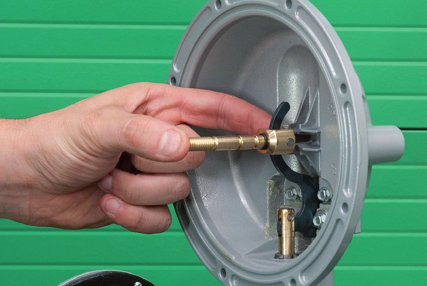
PRECAUTION                                                                                                    EN

    GENERAL PRECAUTION
    The apparatus described in this manual is a device subject to pressure installed in systems under pressure;
    The apparatus in question is normally installed in systems for transporting flammable gases (natural gas, for exaple).

    PRECAUTION FOR THE OPERATORS
    Before proceeding with installation, commissioning or maintenance, operators must:
    •        Examine the safety provisions applicable to the installation in which they must work;
    •        Obtain the authorisations necessary for working when required;
    •        Use the necessary means of individual protection (helmet, goggles, etc.);
    •        Ensure that the area in which they operate is fitted with the means of collective protection envisaged and
             with the necessary safety indications.

    PACKING
    The packing for transportation of equipment and of relevant spare parts are designed and shaped to avoid damage to
    any part during transportation, warehousing and handling activities. Therefore the equipment and spare parts shall be
    kept into their packing until their installation in the final site. After packing is open, check that no damage occurred to
    any goods. If damage occurred inform the supplier and keep packing for any verification.

    HANDLING
    The handling of the apparatus and of its components must only be carried out after ensuring that the lifting gear is
    adequate for the loads to lift (lifting capacity and functionality). The apparatus must be handled using the lifting points
    provided on the apparatus itself.
    Motorised means must only be used by the persons in charge of them.

    INSTALLATION
    The installation of the pressure regulator has to occur in compliance with the provisions (laws or standards) in force in
    the place of installation.
    In detail, natural gas plants have to show features in compliance with the law provisions and standard requirements in
    force in the place of installation or at lease in compliance with standards EN 12186 or EN 12279; in detail, it is neces-
    sary to meet the provisions of paragraphs 6.2, 7.5.2, 7.7, 9.3 of the standard EN 12186 and 6.2, 7.4, 7.6, 9.3 of the EN
    12279 standard. The installation in compliance with such standards minimizes the risk of fire hazard and the formation
    of potentially explosive atmospheres.
    The valve is not equipped with external pressure limitation devices; therefore, it has to be installed making sure that
    the operating pressure of the assembly on which it is installed does not exceed the maximum allowable pressure
    (PS).
    Therefore, the user, as deemed necessary by the same, shall install on the assembly suitable pressure limitation sy-
    stems, as well as provide the plant with suitable relief or drain systems in order to discharge the pressure and fluid
    contained in the plant before proceeding with any inspection and maintenance activity.
    If the installation of the apparatus requires the application of compression fittings in the field, these must be installed
    following the instructions of the manufacturer of the fittings themselves. The choice of the fitting must be compatible
    with the use specified for the apparatus and with the specifications of the system when envisaged..

    START UP
    Commissioning must be carried out by adequately trained personnel.
    During the commissioning activities, the personnel not strictly necessary must be ordered away and the no-go area
    must be properly signalled (signs, barriers, etc.).
    Check that the settings of the apparatus are those requested; if necessary, reset them to the required values in accor-
    dance with the procedures indicated in the manual.
    When commissioning, the risks associated with any discharges into the atmosphere of flammable or noxious gases
    must be assessed.
    In installations in natural gas distribution networks, the risk of the formation of explosive mixtures (gas/air) inside the
    piping must be considered.

    COMPLIANCE WITH DIRECTIVE 2014/68/EU (PED)
    The SQD-1 regulators are classified as Fail Open regulators and as Integral Strength (IS) according to EN 334 and are
    therefore definied as safety accessories according to Directive 2014/68/EU (PED).

Dival SQD-1 - MT 234-E - 02-2020                                                                                       4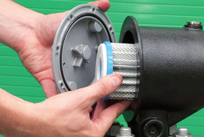
E                                                                                 INDEX

1.0         INTRODUCTION                                                                                    6
1.1         Main  features                                                                                  6
1.2         Operation of the pressure regulator SQD-1                                                       6
1.3         Setting springs                                                                                 8

2.0         INSTALLATION                                                                                    9
2.1         General                                                                                       9
2.2         Connecting the apparatuses                                                                   10
2.3         Downstream  volume required for installation                                                 11

3,0         MODULARITY’                                                                                  11
3.1         LA/.. Incorporated slam-shut                                                                 11
3.2         LA/.. Slam-shut setting springs                                                              13

4.0         ACCESSORIES                                                                                  14
4.1         Relief Valve                                                                                 14
4.1.1       Direct installation in the line                                                              14
4.1.2       Installation                                                                                 15

5.0         START UP                                                                                     15

5.1         General                                                                                      15
5.2         Gas input, control of external tightness and setting                                         16
5.3         Commissioning the regulator                                                                  17
5.4         Commissioning the regulator with incorporated LA/..Slam-shut                                 17

6.0         TROUBLE-SHOOTING                                                                             19

6.1         Table 5  regulator SQD 100                                                                   20
6.1         Table 6  slam-shut                                                                           20

7.0         MAINTENANCE                                                                                  21

7.1         General                                                                                      21
7.2         SQD 100 regulator maintenance procedure                                                      22
7.3         Replacement filter                                                                           29
7.4         LA/.. Slam-shut valve                                                                        33

8.0         FINAL OPERATION                                                                              34
8.1         Checking the tightness and setting                                                           34
8.2         Start up                                                                                     34

        5                                                                  Dival SQD-1 - MT 234-E - 02-2020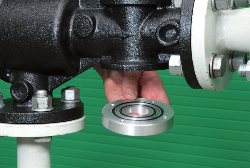
DESCRIPTION                                                                                                   EN

1.0   INTRODUCTION
      The scope of this manual is to provide the essential information for the installation, commissioning, disassembly, re-
      assembly and maintenance of SQD-1 regulators.
      It is also appropriate to provide a brief illustration of the main features of the regulator and of its accessories.

1.1   MAIN FEATURES

      The SQD-1 pressure regulator is a pressure regulator for previously cleaned gaseous fluids and is suitable for medium
      and low pressures.
      The SQD-1 is a normally open regulator and consequently opens in the event of:
      - Breakage of the main diaphragm;
      - No regulated pressure signal.
      The main specifications of this regulator are:

       Design pressure PS:                         up to  6 bar
       Operating Temperature range:                -20 °C to +60 °C
       Ambient Temperature range:                  -20 °C to +60 °C
       Inlet pressure range  bpu:                  from 0,2 to 6 bar
       Possible regulation range Wd:               10 to 300  mbar;
       Minimum differential pressure:              0,1  bar
       Accuracy class AC                           up to 10 (according to the output pressure field);
       Lockup pressure class SG:                   up to 20 (according to the output pressure field)
                                                                                                     Main feature         TAB. 1

1.2   OPERATION OF THE PRESSURE REGULATOR  SQD 100 (fig. 1)

      In absence of pressure the obturator 3 is kept in open position from the hook of shaft 9 on the side of the levers 13
      (fig. 1). The outlet pressure Pd  is checked through the comparison between the load of the spring 43 and the impulse
      of the outlet pressure on the membrane 19.
      In this comparison are involved also the weight of the mobile equipment and the dynamic thrusts on the obturator.
      The upstream pressure, although it is variable, has not any influence on the balance of the obturator 3, since this latter,
      due to the presence of the hole A, is positioned between two equal pressures acting on equal surfaces.
      The movement of the diaphragm 9 is transmitted by the lever system 13 to the stem 9 and hence to the obturator 3.
      The obturator 3 is fitted with a vulcanized rubber gasket to ensure perfect tightness with zero flow rate demand.
      If, during operation, the downstream pressure drops, the force it exerts on the diaphragm 19 becomes lower than the
      load of the spring 43. The diaphragm therefore drops and, by means of the lever system 13, pulls the obturator 3 away
      from the valve seat 2. The gas flow, therefore, increases until the initial pressure set-point is restored.
      If, on the other hand, the downstream pressure begins to increase, the force exerted on the diaphragm 19 exceeds
      the load the spring 43. The obturator is therefore displaced towards the closed position, returning the downstream
      pressure the set-point.
      In normal working conditions, the obturator 3 is positioned in such a way as to maintain the pressure Pd around the
      selected set-point.
      To adjust the pressure set-point you con turn the internal adjustment ring 28 appropriately, clockwise to increase
      and anticlockwise to reduce it. Normally the plug is only used the cover the lower band of the various setting ranges;
      the adjusting screw is used for the higher values. The pressure regulator is equipped with two anti-pumping devices
      33 and 34 (fig. 1), which are in charge of slowing down the inflow/outflow of the gas/air in the head only during the
      transitory phases, in order to avoid possible oscillation phenomena of the regulated pressure.

      There are also two stops V1 and V2 for the purpose of eliminating damaging effects which could derive from accidental
      over-pressures below the diaphragm 19 or from overloading of the spring 43.

      Usually, a solution of the type shown in fig. 2a is adopted in order to protect the obturator against damages resulting
      from sudden increases of the regulated pressure.

  Dival SQD-1 - MT 234-E - 02-2020                                                                                       6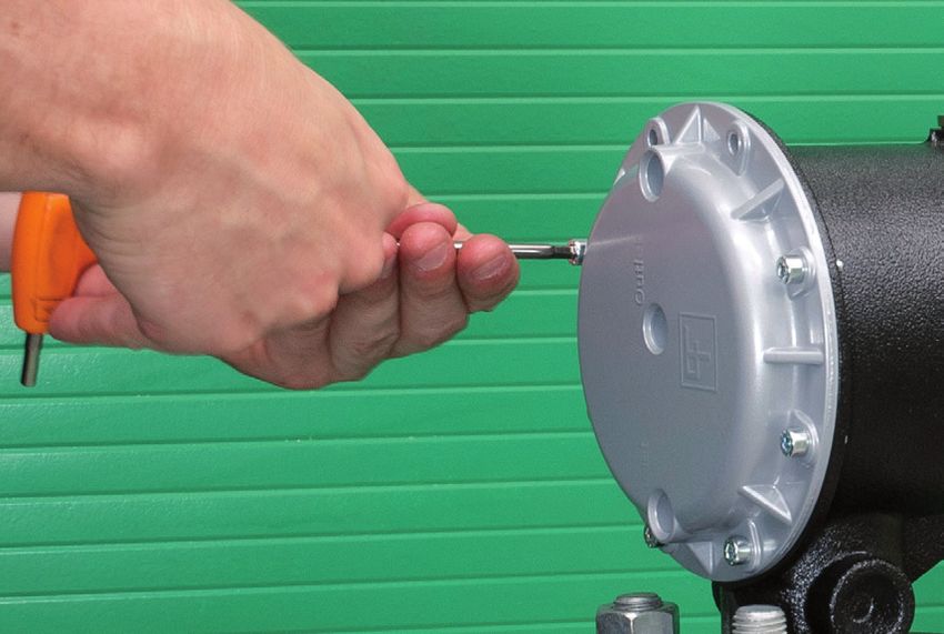
EN                                                                                          DESCRIPTION

                                                     33                                   19

                                                                                          V1

                                                                                          13

                                                                                          43

                                                                                          28
                                      46    A
                                                                                          34

                                                                                          9

                                                                                          3

                                                                                          2

                                                                                   566

                                                48   166

                                                                                  SQD-1 Pressure regulator:   Fig. 1

    In fact, this solution allows the diaphragm protection disc 20 to rest on the upper stroke end V1 exceeding
    the load of the spring 42 and thus releasing the obturator from the load resulting from the sudden pressure
    increase.
    In order to prevent small leaks at null required flow rate or that sudden and temporary overpressures, re-
    sulting for example from fast manoeuvres or gas overheating, may let the slam-shut valve trip, the solution
    shown by fig. 2a can be transformed, upon request, into an embedded relief valve, eliminating the O-ring
    73 and adding the ring 70 (fig. 2b).
    Its operation is described as follows: with closed regulator, any overpressures lift the diaphragm protection
    disc 20 exceeding the load of the springs 42 and 43. In this way, a given quantity of gas is discharged through
    the seat Z of the relief valve.

7                                                                         Dival SQD-1 - MT 234-E - 02-2020
DESCRIPTION                                                                                                        EN

                                                           43                                                            43

                                                           42                                                            42

                            73

                                                                                                                         Z
                            70                                                           70

                                                           20                                                            20

                Fig.2a                                               Particular spring                                         Fig. 2b

1.3      Tab. 2 SETTING SPRINGS

         Table 2 shows the calibration fields of the different foreseen springs.
         - 1 Code n° 64470024BI is for internal relief application (10 -18 mbar) *
         - 2 Code n° 64470031RO is for internal relief application (10 -50 mbar) *
         - 3 Code n° 64470038GI is for internal relief application (30 -100 mbar) *

		       * Differential relief valve operating pressure with reference to the nominal outlet pressure (Pd)

          SPRINGS CHARACTERISTICS                        SQD 100 BP
          Code                           Colour                 De               Lo           d             Setting range  (mbar)
          64470137RO                     RED                    34              115           1.8                  13 - 18
          64470024BI                     WITE                   15               45           1.3
          64470068GI                     YELLOW                 34              115            2                   19 - 25
          64470031RO                     RED                    15               40           1.7
          64470139NE                     BLACK                  34              115           2.2                  26 - 35
          64470031RO                     RED                    15               40           1.7
          64470140MA                     BROWN                  34              106           2.7                  36 - 65
          64470031RO                     RED                    15               40           1.7
          64470071GR                     GREY                   34              118           2.8                 66 - 100
          64470031RO                     RED                    15               40           1.7
          De  = external diameter     d  = wire diameter      Lo  =  length * = for internal relief valve
                                                                                                                   Springs      Tab. 2

          SPRINGS CHARACTERISTICS                        SQD 100 MP
          Code                           Colour                 De               Lo           d             Setting range  (mbar)
          64470141VE                     GREEN                  34              120           3.2                 101 - 170
          64470038GI                     YELLOW                 15               40            2
          64470329AZ                     LIGHT BLUE             34              111           3.8                 171 - 300
          64470038GI                     YELLOW                 15               40            2
          De  = external diameter     d  = wire diameter      Lo  =  length * = for internal relief valve
                                                                                                                   Springs      Tab. 2

     Dival SQD-1 - MT 234-E - 02-2020                                                                                          8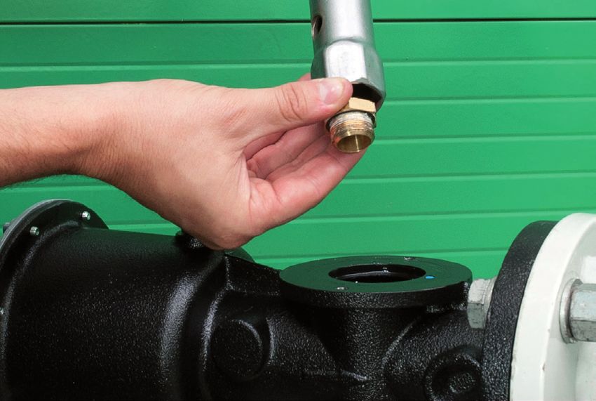
EN                                                                                                   INSTALLATION

2.0       2.0     INSTALLATION

2.1       GENERAL

          Pressure regulator does not require any supplementary upstream safety accessory for protection against overpressu-
          re compared with its design pressure PS, when upstream reducing station is sized for a max downstream incidental
          pressure MI Pd ≤ 1,1 PS.

          Before installing the regulator it is necessary to ensure that:
          - The regulator can be inserted in the space provided and that subsequent maintenance operations will be sufficien-
             tly practicable (see overall dimensions in Fig. 3);
          - Inlet and outlet pipings must be at the same level and able to carry the weight of the regulator (see Fig. 3);
          - The inlet/outlet flanges of the piping are 90°l;
          - The inlet/outlet flanges of the regulator are clean and the regulator itself has not been subject to damage during
             transport;
          - The piping upstream has been cleaned to expel residual impurities such as welding scale, sand, paint residues,
             water, etc.
          The usually foreseen arrangement is the one indicated in figure 4.

                                                                                   161,3

                                                                                                460
                                                                                   124,3

                                                 160

                                                         259
                                                 330,5

           Pressure regulators without slam-shuth:       Kg.13
           Pressure regulators with slam-shut:           Kg. 14
                                                                                           Overall dimensions and weights:   Fig. 3

      9                                                                            Dival SQD-1 - MT 234-E - 02-2020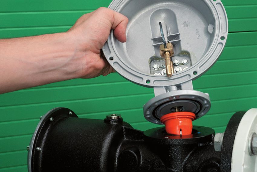
INSTALLATION                                                                                                  EN

2.2   CONNECTING THE DEVICES

      The connections between the apparatus and the main piping must be made using stainless steel or cooper pipe with
      minimum internal diameter of 8 mm.

                                                                  Pressure regulator

                                                                                             Contol pressure gauge

                                                                                             Bleed cock

                                                                                  On/off valve

                                                                                                 Installation scheme:    Fig. 4

                                                                                         Detail of multiple take-off:    Fig. 5

  Dival SQD-1 - MT 234-E - 02-2020                                                                                      10
EN INSTALLATION
The installation of a multiple plug on a plant has its aim in in taking from a single point all the pressure impulse signals
that go to the different reduction- safety devices and to their accessories.
The regulator must be installed in the line with the arrow on the body pointing in the gas flow direction.
It is indispensable for good regulation for the position of the downstream pressure take-offs and the speed of the gas
at the take-off point respect the value given.
The regulator, when used in gas pressure reduction stations, has to be installed at least according to the requirements
set forth by the standards EN 12186 or EN 12279. All points for possible gas relief due to possible breaks of sensors/
diaphragms are to be conveyed according to standards EN 12186 or EN 12279.
The following is recommended so as to prevent the accumulation of impurities and condensate in the lines of the
pressure take-off.
a) The lines themselves must slope down towards the downstream piping with a slope of about 5-10%;
b) The connectors on the piping must always be welded on the top of the piping itself and there must be o burr
or inward protrusions in the hole in the piping.
The speed of the gas must not exceed the following values in the piping down-stream from the regulator:
Vmax = 15 m/s
ATTENTION!
2.3 DOWNSTREAM VOLUME REQUIRED FOR INSTALLATION
In the case of a service regulator of the ON-OFF type (stopping or starting of burners), you should remember that
though the SQD- 100 apparatus is classified as being of the fast reaction type, it requires an appropriately dimensioned
volume of gas between the apparatus itself and the burner so as to partly absorb the pressure swings caused by fast
flow rate variations.
3.0 MODULARITY
The modular-type conception of SQD-1 regulators means that it is also possible to fit the slam-shut incorporated with
the body itself even after the installation of the regulator.
3.1 LA/.. INCORPORATED SLAM SHUT
This is a device (fig. 7 and 8) which immediately blocks the gas flow if, because of some failure, the downstream pres-
sure reaches the point set for its intervention, or if it is actuated manually.
Wait the SQD-1 pressure regulator, the slam-shut be incorporated on both the service regulator or on the in-line mo-
nitor. Three versions (LA/BP, LA/MP and LA/TR) are available depending on the intervention pressure ranges
The main features of the slam-shut device are as follows:
• Design pressure PS: up to 20 bar;
• Intervention for pressure increase and/or decrease;
• Intervention accuracy AG: ± 5% of the set point for pressure increase (based on setting-pressure); ± 15% of
the set point for pressure drop (based on setting-pressure);
• internal by-pass device;
• manual button-operated actuating device.
N.B. WE RECOMMEND NOT TO PUT ON/OFF VALVES ON THE IMPULSE TAKE-OFFS
ATTENTION!
11 Dival SQD-1 - MT 234-E - 02-2020INSTALLATION EN
General Lay-out: Fig. 6
58
61
65
64
62
Detail of manual button
operated actuating de-
vice
N.B.: L’O-ring is used for
specific version.
LA/...Slam-shut: Fig. 7
Dival SQD-1 - MT 234-E - 02-2020 12EN INSTALLATION
The slam-shut valve LA/.. consists essentially of an obturator (fig. 7) fitted on a stem, a releasing lever system, a con-
trol head and a manual resetting system. The pressure to control Pd, in chamber C of the control head, acts on the
diaphragm 46 which is integral with the cam shaft 45.
The load of the pressure Pd on the diaphragm is countered by the springs 34 and 35 which respectively determine
intervention for pressure increase and pressure decrease. The device is set by turning the rings 17 and 18. Turning the
rings clockwise increases the intervention value; turning anticlockwise decreases it.
Intervention as a result of a pressure increase occurs as follows: when the pressure Pd exceeds the set point the load
on the diaphragm 4 increases until it overcomes the resistance of the spring 34. This causes the shaft 45 to translate
towards the left so that the cam shifts the feeler 33 and trips the lever mechanism 29. In this way, the stem 5 with the
obturator 19 is freed and closed by the spring 8.
IOn the other hand, intervention as a result of a pressure decrease occurs as follows: as long as the pressure Pd stays
above the load of the spring 35, the spring support 13 rest on the support 12.
If the pressure Pd drops below the set point, the spring 35 translates the support 13 to the right and with it the shaft
45.
The cam shifts the feeler 33 and trips the lever mechanism 29. The slam-shut is reset by unscrewing the bushing 7 and
pulling it downwards until the lever system 29 is reset.
During the first phase of the operation, it will be necessary to wait until the upstream pressure, through the internal
by-pass, passes downstream from the obturator to rebalance it. After resetting, the bushing 7 must be screwed back
to its seat.
It is possible to see from the outside whether the slam-shut is open or closed by observing the position of the nut 37
through in the bushing 7, as shown in figure 7.
Table 3 lists the range of intervention of the pressure switches available.
3.2 LA/… SLAM-SHUT SETTING SPRINGS
LA/BP SLAM-SHUT SPRING CHARACTERISTICS
Code Colour De Lo d Setting range in mbar
Intervention for max. pressure
64470112 RO RED 43 2.2 30 ÷ 50
34
64470115GR GREY 42 2.8 50 ÷ 180
Intervention for min. pressure
64470024BI WHITE 15 45 1.3 6 ÷ 60
LA/MP SLAM-SHUT SPRING CHARACTERISTICS
Code Colour De Lo d Setting range in mbar
Intervention for max. pressure
64470115GR GREY 34 42 2.8 140 ÷ 180
64470116GI YELLOW 40 3.2 180 ÷ 280
64470051BI WHITE 50 3.2 280 ÷ 450
Intervention for min. pressure
64470024BI WHITE 15 45 1.3 10 ÷ 60
6470038GI YELLOW 40 2 60 ÷ 240
De = external diameter d = wire diameter Lo = Length
LA/.. Slum-Shut Tab. 3
13 Dival SQD-1 - MT 234-E - 02-2020INSTALLATION EN
4.0 ACCESSORIES
4.1 RELIEF VALVE
The relief valve is a safety device which releases a certain quality of gas to the exterior when the pressure at the con-
trol point exceeds the set-point as a result of short-lasting events such as, for example, the very fast closing of the on/
off valves and/or overheating of the gas with zero flow rate demand. The release of the gas to the exterior can, for
example, delay or block the intervention of the slam-shut valves for transitory reasons deriving from damage to the
regulator.
Obviously the quantity of gas released depends on the extent of the overpressure with respect to the set-point.
The different models of relief valves available are all based on the same operating principle which is illustrated below
with reference to the valve VS/AM 65 (fig. 8). It is based on the contrast between the thrust on the diaphragm 24
deriving from the pressure of the gas to control and the thrust from the setting spring 20. The weight of the mobile as-
sembly, the static thrust and the residual dynamic thrust on the obturator 4 also contribute to this contrast. When the
thrust deriving from the pressure of the gas exceeds that of the setting spring, the obturator 4 is raised and a certain
quality of gas is released as a result.
As soon as the pressure drops below the set-point, the obturator returns to the closed position.
Proceed as indicated below to control and adjust intervention of the relief valve.
VS/AM65: Fig. 8
4.1.1 DIRECT INSTALLATION IN THE LINE (fig. 9).
When the relief valves fitted directly in the line that is, without the interposition of an on/off valve, we recommend
proceeding as follows:
1) Ensure that the downstream on/off valve V2 and the bled cock 6 are closed;
2) Connect to the cock 6 a controlled auxiliary pressure and stabilize it to the wished tripping value of the relief
valve. Open the bleed cock 6 with a following increase in the pressure of the downstream section;
3) Check intervention of the relief valve and ad just it if necessary by turning the internal adjustment ring 14
appropriately (clockwise to increase the set-point, anticlockwise to reduce it).
Dival SQD-1 - MT 234-E - 02-2020 14EN INSTALLATION
Direct installation: Fig. 9
4.1.2 INSTALLATION WITH ON/OFF VALVE (fig. 10)
1) Close the on/off valve 16;
2) Connect a controlled auxiliary pressure to the take-off valve 17 and increase it slowly to the envisaged inter-
vention value;
3) Check intervention of the relief valve and ad just it if necessary by turning the interna adjustment ring 14
appropriately (clockwise to increase the set-point, anticlockwise to reduce it).
Installation With On/Off Valve : Fig. 10
5.0 START UP
5.1 GENERAL
After installation, check that the inlet/outlet on/off valves, any by-pass and the bleed cock are closet.
Before commissioning, you must ensure that the conditions of use comply with the characteristics of the apparatu-
ses.
These characteristics are recalled by the symbols on the specification plates applied to each apparatus (fig. 11).
We recommend actuating the opening and closing valves very slowly.
The regulator could be damaged by operations which are too fast.
15 Dival SQD-1 - MT 234-E - 02-2020INSTALLATION EN
Apparatus Specification plates: Fig. 11
The list of symbols used and their meanings are listed below:
Pumax= maximum operating pressure at the inlet of the apparatus.
bpu= range of variability of the inlet pressure of the pressure regulator in normal operating conditions.
PS= maximum pressure for which the body and its inner metallic partition walls are designed in accordance with
the strength requirements in this document.
Wds= setting range of the pressure regulator which can be obtain using the parts and the setting spring fitted at
the moment of testing (that is without changing any components of the apparatus.
Wd= setting range of the pressure regulator which can be obtain using the parts and the setting spring fitted at
the moment of testing
Cg e KG = experimental coefficient of critical flow.
AC= regulation class
SG= closing pressure class.
AG= intervention accuracy
Wdso= range of intervention for the over pressure of slam-shut which can be obtain using the setting spring fitted
at the moment of testing.
Wdo= range of intervention for the over pressure of slam-shut which can be obtain using the setting springs indi-
cated in the tables.
Wdsu= range of intervention for pressure decrease of slam-shut which can be obtain using the setting spring fitted
at the moment of testing.
Wdu= range of intervention for pressure decrease of slam-shut which can be obtain using the setting springs indi-
cated in the tables.
5.2 GAS INPUT, CONTROL OF EXTERNAL TIGHTNESS AND SETTING
The pressurization of the equipment shall be performed very slowly. Should not any stabilization procedure be carried
out, it is recommended to keep gas speed in the feeding piping at a value equal to 5 m/sec during pressurization.
To protect the apparatus from damage, the following operations must never be carried out:
• Pressurization through a valve located downstream from the apparatus itself.
• Depressurization through a valve located upstream from the apparatus itself.
External tightness is guaranteed if no bubbles form when a foam medium is applied on the element under pressure.
The regulator and any other apparatuses (slam-shut, monitor) are normally supplied already set for the desired set-
point. It is possible for various reasons (e.g., vibration during transport) for the settings to be changed while remaining
within the values permitted by the springs used.
We therefore recommend checking the settings using the procedures illustrated below.
In installation consisting of two lines, we suggest commissioning one line at a time, starting from the one with the
lover set-point, known as the “reserve” line. The set-point of the apparatuses in the line will obviously deviate from
those specified in the table 4.
Dival SQD-1 - MT 234-E - 02-2020 16EN INSTALLATION
Before commissioning the regulator you must check that all the on/off valves (inlet, outlet, any by-pass) are closet and
that the gas is at a temperature which will not lead to malfunction.
5.3 COMMISSIONING THE REGULATOR
If there is also a relief valve in the line, refer to par. 4.1 to check it
Fig. 12
1) partially open the downstream bleed cock 6;
2) very slowly open the inlet on/off valve V1;
3) stabilize pressure upstream and downstream; through the pressure gauge 5 check that the downstream pres-
sure shows the wished calibration value. Otherwise, adjust the calibration acting on the proper internal ring
nut (fig. 1), rotating it clockwise to increase and counter-clockwise to decrease;
5) close the bleed cock 6 and verify the tightness of the regulator and the value of its closing overpressure;
6) check the tightness of all the joints between the on/off valves V1 and V2 using a foam Solution;
7) very slowly open the downstream on /off valve V2, until the line is completely filled.
5.4 COMMISSIONING THE REGULATOR WITH INCORPORED LA/.. SLAM-SHUT
If there is also a relief valve in the line, refer to par. 4.1 to check it.
Fig. 13
17 Dival SQD-1 - MT 234-E - 02-2020INSTALLATION EN
Check and adjust the intervention of the slam-shut 7 as follows:
A)For slam-shut connected to the downstream piping by a three-ways deviator “push” valve 11, (fig 14) proceed
as follows:
- connect a controlled auxiliary pressure to path C;
- stabilise this pressure at the set point established for the regulator;
- press knob 1 of the three-way “push” valve completely;
- reset the slam-shut device by means of the provided threaded bushing;
- keep the knob 1 pressed and:
• for safety devices which intervene for maximum pressure: slowly increase the auxiliary pressure and
check the intervention value. If necessary, increase the intervention value by turning the adjustment ring
18 clockwise, or anticlockwise to reduce the intervention value.
• for safety devices which intervene for pressure increase and reduction: slowly increase the auxiliary
ressure and record the intervention value. Restore the pressure to the set point established for the regula-
tor, and carry out slam-shut reset operation.
- Check intervention for pressure reduction by slowly reducing the auxiliary pressure. If necessary, increase the
ntervention values for pressure increase or decrease by respectively turning the rings 18 and 17 clockwise
and vice-versa to reduce them.
- check proper operation by repeating the operations at least 2-3 times.
Rest position
(A and B communication)
Cham-
Controll position ber with
controlled
(A and C communication) pressure
Enviroment with the pressare
to keep under control
Fig. 14
B) On devices without the “push” valve (fig. 15) we recommend connecting the control head separately to a con-
trolled auxiliary pressure and repeating the operations described above
Chamber
with control-
led pressure
Enviroment with the pressare
to keep under control
Fig. 15
Dival SQD-1 - MT 234-E - 02-2020 18EN TROUBLE-SHOOTING
At the end of the operation, reconnect the control head to the downstream pressure take-off
ATTENTION!
N.B.: The intervention tests should be repeated at last every months.
At the end of the slam-shut check, proceed as follows:
1) Make sure the block is on closing-position;
2) Open the inlet block valve V1;
3) Open very slowly the block valve, pulling the compass;
4) Partially open the relief faucet 6 placed on the outlet piping;
5) Check, through pressure gauge 5, that the outlet pressure has the gauging value indicated by the regulator.
If not, it is then necessary to adjust the gauging value, operating on the internal clamp, rotating it clockwise to
increase and anti-clockwise to decrease;
6) Close the relief faucet 6 and check the value of the closure pressure;
7) Using a foaming agent, check the capacity of all the joints placed between block valves V1 and V2;
8) Open very slowly the outlet block valve V2, until the piping gets completely full;
9) It is advisable to check that, activating the block valve manually, the line capacity gets stopped.
Regulator set-point
Relief Valve Slam-shut Max Slam-shut Min
(Pds) mbar
10TROUBLE-SHOOTING EN
6.1 SQD-1 Pressure regulator (fig.35 - 36 - 37 - 38)
PROBLEM POSSIBLE CAUSES REMEDY
Valve seat [2] damaged Replace
Obturator [211] damaged Replace
O-ring [202] damaged Replace
No tightness at Q=0 O-ring [208] damaged Replace
O-ring [210] damaged Replace
O-ring [209] damaged Replace
Diaphragm [206] damaged Replace
Dirt or foreign bodies in the seal area Clean
Clean and, if necessary, replace
Anomalous friction of the rod-obturator
sealing and/or guide elements
Pumping
Antipumping valves blockage Clean and replace if necessary
Reduced downstream volumes Increase volume
Increase Pd with Q>0 Diaphragm [322] breakage Replace
Diaphragm [206] breakage Replace
Tab. 5
6.2 SLAM-SHUTH LA/… (fig. 35 - 38)
PROBLEM POSSIBLE CAUSES REMEDY
Slam-shut obturator does not
Control head diaphragm [21] ruptured Change the diaphragm
close
Leakage from slam-shut Obturator gasket [27] deteriorated Change the gasket
obturator O-ring [166] worn Change
Obturator seat [2] eroded or pitted Change the seat
Wrong setting of max and/or minimum Make the setting again using the
Incorrect intervention pressure spring rings [12] and/or [13]
Friction in lever systems Change
Rearming not Persistence of the cause which led to pres- Decrease or decrease the down-
possible sure increase or decrease downstream stream pressure
Lever systems broken or chipped Change
Tab. 6
N.B. If the slam-shut has intervened, close the inlet and outlet valve (V1 and V2) in the line and discharge the pressure
before carrying out any operation.
Eliminate the causes which gave rise to intervention before reactivating it. In the event of operating problems
when personnel qualified for a specific operation are not available, call the service centre nearest to you.
For further information contact our SATRI service centre at our Arcugnano (Vicenza) works
Dival SQD-1 - MT 234-E - 02-2020 20EN MAINTENANCE
7.0 MAINTENANCE
7.1 GENERAL
Periodical inspection and maintenance shall be carried out according to the regulations in force (kind and frequencies).
Before carrying out any operation it is important to ascertain that the regulator has been cut off both upstream the
regulator and the on/off valves. The maintenance operations are closely associated with the quality of the gas tran-
sported (impurities, humidity, gasoline, corrosive substances) and with the efficiency of the filtering.
Preventive maintenance should be carried out at intervals which, if not established by regulation in force, depend
on:
- The quality of the gas transported;
- The cleanliness and conservation of the piping upstream from the regulator: in general, for example, when
starting the equipment for the first time, more frequent maintenance is required because the precarious
state of cleanliness inside the piping;
- The level of reliability required from the regulation system.
Before starting the disassembly operations on the apparatus you should check that:
- A set of recommended spares is available. The spares must be original Fiorentini ones, bearing in mind that
the more important ones such as diaphragms are marked;
- A set of wrenches is available as specified in table 7.
For a proper maintenance the recommended spare arts are unequivocally identified by labels indicating:
- The No of assembly drawing SR of the apparatus for which the spare parts are suitable;
- The position showed in the assembly drawing SR of the apparatus.
- We advise to replace all rubber-made parts. In order to do this, please use the appropriate replacing kit.
N.B. Pietro Fiorentini S.p.A. is in no case responsible, in case of use of non-original replacements.
Before starting disassembling the equipment, it is also necessary to make sure that the plant section on which one is
working is not operating upstream or downstream, as well as that the pressure in the involved piping section has been
discharged.
The depressurization manoeuvre has to be carried out paying attention to discharge the bleed cocks to the drains in
a safe area. To avoid the risk of generating sparks due to bumps of impurity particles within the discharge lines, it is
recommended to keep the fluid speed lower than 5 m/sec.
Moreover, it is suggested to perform reference marks, before disassembling the equipment, on the parts that may
show problems of mutual orientation or positioning during re-assembly.
Finally, it shall be underlined that the O-rings and the mechanical sliding parts (stems, etc.) must be lubricated, before
re-assembling them, with a thin layer of silicone grease. Before commissioning, the external tightness of the equip-
ment has to be tested at a suitable pressure in order to assure the absence of external leaks.
The internal tightness of the block devices and of the monitors, when these are used as safety accessories according to
the PED Directive, has to be tested at a suitable pressure in order to assure the internal tightness at maximum foreseen
operating pressure. Such tests are essential to assure the safe use under the foreseen operating conditions. They have
in any case to comply with the national regulations in force.
21 Dival SQD-1 - MT 234-E - 02-2020MAINTENANCE EN
7.2 SQD-1 REGULATOR MAINTENANCE PROCEDURE
Device status: installed and disconnected from gas grid
Authorized personnel: maintainer
Necessary equipment: see “Tab.7”
Preliminary Operation:
• Ensure that the pressure upstream and downstream from it is 0
• On the axis of the regulator, tick with a permanent marker the joints of the different elements. This action acts as
a guide and help the later reassembling phase.
SQD-1 Pressure regulators Fig. 16
Dival SQD-1 - MT 234-E - 02-2020 22EN MAINTENANCE
Spring extractiong: Fig. 17
2. Completely unscrew the tap (326) and the internal regulating clamp (318). Then take out the spring (328);
Remove low support cap: Fig. 18
3. Remove the screws (314) that fix the low support cap (301) with the high support cap (312);
Remove cap: Fig. 19
4. Remove the high cap (312);
23 Dival SQD-1 - MT 234-E - 02-2020MAINTENANCE EN
Nut extractiong: Fig. 20
5. Remove the screw-nut (311) and extract the spring holder (31).
Nut extractiong: Fig. 21
6. Unscrew the screw-nut (324).
Membrane extractiong: Fig. 22
7. Dismantle the protection disc (323), the membrane (322) and the membrane-support (321);
Dival SQD-1 - MT 234-E - 02-2020 24EN MAINTENANCE
Check internal levers: Fig. 23
8. Check, by increasing and decreasing, the correct functioning of the internal levers (305);
Screws extractiong: Fig. 24
9. Take the screws out (46)
Head and balancing group extractiong : Fig. 25
10. Separate the head (300) and the balancing group (200) from the regulator’s body (1);
25 Dival SQD-1 - MT 234-E - 02-2020MAINTENANCE EN
Balancing group extractiong : Fig. 26
11. Separate the balancing group (200) from the head (300) by modifying the flowing-direction of the gas in order to
get the shaft (308) getting out of the loading joint (212);
Balancing group disassembling : Fig. 27
12. Unscrew the screw (214) from the obturator (211) and separate alll the components of the balancing group
(200);
Valve seat extractiong: Fig. 28
13. Unscrew the valve seat from the body (2), paying attention not to damage the sustain rims;
Dival SQD-1 - MT 234-E - 02-2020 26EN MAINTENANCE
Slam-shut screw extractiong: Fig. 29
14. Unscrew the screws (48).
Slam-shut extractiong : Fig. 30
15. Remove the slam-shut valve with pad
27 Dival SQD-1 - MT 234-E - 02-2020MAINTENANCE EN
Slam shut flange removal: Fig. 31
16. Unscrew and remove the screw [48] and remove the flange [556]
To re-install the regulator you can carry out the operations described for the dismantling, in the opposite way.
Before re-installing the sustain elements (o-rings, membranes, etc…), it is necessary to check their integrity and if that
is the case to replace them. It is necessary to make sure that the membrane (209) is perfectly inserted in its seat and
that the movement of the shaft-obturator group shows no obstruction.
You have to be very careful in manipulating the valve seat (2), not to damage the sustain rims.
The internal regulation clamp (318) must be only partially activated.
The maintenance just of the regulation valve (balancing group 300 and valve seat 2) can be carried out without
having to intervene on the control head.
In this case, the operations to be followed start from position 9 after having implemented the position 1 opera-
tion.
Dival SQD-1 - MT 234-E - 02-2020 28EN MAINTENANCE
7.3 FILTER REPLACEMENT
Device status: installed and disconnected from gas grid
Authorized personnel: maintainer
Necessary equipment: see “Tab.7”
Cover removal: Fig. 32
1. Unscrew and remove screws from cover;
Cover removal: Fig. 33
2. Pull out the cover;
29 Dival SQD-1 - MT 234-E - 02-2020MAINTENANCE IT
Filter cartridge replacement: Fig. 34
3. Pull out filter cartridge.
Dival SQD-1 - MT 234-E - 02-2020 30EN MAINTENANCE
33 19
V1
13
43
28
46 A
34
9
3
2
566
48 166
Pressure regulator: Fig. 35
31 Dival SQD-1 - MT 234-E - 02-2020MAINTENANCE EN
318 326
307 325
328
311
324
327
313
323
322
312
308
301
321
317 306
310 316
321 309 305 302
Standard head: Fig. 36
212
207
202
209
210
213
201
206b
203b
208
204
214 211
Balance: Fig. 37
Dival SQD-1 - MT 234-E - 02-2020 32EN MAINTENANCE
7.4 VLA/:: SLAM SHUTH VALVE (fig. 38)
1) Make sure that the slam-shut valve is in closed position;
2) Disconnect the fittings between the slam-shut valve and the downstream pressure connection;
3) Remove the screws tightening the slam-shut valve to the body;
4) Unscrew the plug (20) and the regulation nuts (17) and (18); then, extract the calibration springs (34) and (35) and
the spring supports (12) and (13);
5) Remove the screws (41) and disassemble the cover (2) with the nut (14);
6) Extract from the body (1) the diaphragm assembly consisting of the parts 45, 46, 48, and 49; to separate them,
unscrew the pin (45) from the tightening nut (49);
7) Remove the nut (37) and unscrew the nut (6) and the threaded bush (7) completely;
8) From the upper part, extract the shaft assembly consisting of the parts 9, 66, 19, 4 and 8, the bushes (22) and (23)
and (19), and the shaft (5). Then, unscrew the shaft (5) and the obturator support (4), and remove the spring ring
(9) to disassemble the obturator (19);
9) Remove the screws (40) and disassemble the anchoring assembly consisting of the parts 29, 30, 33, 36, 38, 39, and
43;
10) Remove the screws (53) to disassemble the flange (51);
11) Finally, to disassemble the release button assembly, unscrew the nut (61) and then unscrew the part (58) from the
pin (62).
To reassemble the slam-shut it is possible to carry out the disassembly operations in the inverse order.
Before reassembling the sealing elements (O-rings, diaphragms, etc.), check their integrity and replace them if neces-
sary
58
61
65
64
62
Blocco LA: Fig. 38
33 Dival SQD-1 - MT 234-E - 02-2020MAINTENANCE EN
8.0 8.0 FINAL OPERATION
8.1 CHECKING THE TIGHTNESSES
1) Very slowly open the on/off valve upstream from the regulator and using a foam solution or the like check:
• the tightness of the external surfaces of the regulator;
• the tightness of the slam-shut;
• the tightness of the internal surfaces of the regulator;
• the tightness of the fitting.
2) Operating very slowly, pull the provided threaded bushing (7), off the slam-shut until only the internal by-pass
is opened. Pull completely to the re-engage position;
3) Check the tightness of the reinforced gasket of the regulator;
4) Open a bleed cock downstream from the regulator to create a small gas flow;
5) Turn the internal adjustment ring (318) until the desired set-point value is reached;
6) Close the bleed cock to the atmosphere.
8.2 START UP
1) Very slowly open the downstream on/off valve and, if necessary, ad just the regulator set-point by means of the
internal adjustment ring (318).
2) Set the tap (326) for normal control head.
Dival SQD-1 - MT 234-E - 02-2020 34EN DISMISSIONE
Below the table “Tools for maintenance”
Type Tool Description
Ch. 8-9-10-11-12-13-14-15-
A • Combination spanner 16-17-18-19-20-21-22-23-
24-25-26-27-41
B • Adiustable spanner L. 30
Ch. 8-9-10-11-12-13-14-15-
C • Compass pin wrench 16-17-18-19-20-24-26-27-
36-46
• Hexagon or allen Key
D Ch. 3-4-5-6-7-8-19
Es.Ch PH 0 x 100 - PH 1x125
E • Philips screwdriver
PH 2x150
• Flat head screwdriver
F 0,5x3x75 1,2x6,5x125
G • Circlip pliers Cod.10÷25 19÷60
Tab. 7
35 Dival SQD-1 - MT 234-E - 02-2020Via Enrico Fermi, 8/10 36057 Arcugnano (VI) Tel. +39 0444 968511 - Fax +39 0444 960468 mail: arcugnano@fiorentini.com - www.fiorentini.com
You can also read