206 Canadian Rule Set 2021 - Briggs Racing
←
→
Page content transcription
If your browser does not render page correctly, please read the page content below
2021
                 206 Canadian Rule Set

                            Effective February 15, 2021
                           (Last updated January 30, 2020)

The 206 engine platform was designed and engineered exclusively for racing. Each
engine is hand-built in Milwaukee, Wisconsin using dedicated tooling and dies to
provide a level of consistency unmatched in the industry today.
The 206 is intended to simplify racing, from hitting the track to the tech process
needed to ensure a level playing field at the end of the day. In combination with
Briggs & Stratton Racing’s slide restriction system a complete racing ladder can be
developed by simply changing a carburetor slide and/or by a slide and ignition
change. With the base engine the basis for today’s ‘box stock’ classifications, the 206
engine gives racers and tracks the ability to have one engine, from start to finish.
All Briggs & Stratton (B&S) racing engines are manufactured solely for sanctioned
racing only. B&S does not recommend the products referenced herein to be used for
any application outside of sanctioned racing as serious injury or death could result.
This rule package has been prepared by Briggs & Stratton Racing and is intended to
establish the sole basis for technical control of the 206 engine in competition. For all
supplemental rules contact your sanctioning body.
CONTENTS

1.     Canadian Eligibility and Briggs & Stratton Racing Class Structure .................. 3-4
2.     These Regulations Are the Only Regulations ..................................................4
2.5.   The 3 Core Rule Set Technical Inspection Principals: ......................................4
3.     Briggs & Stratton 206 Product Availability .....................................................4
4.     General Rules ..............................................................................................5
5.     Things That Are NOT Permitted ................................................................. 5-6
6.     Factory Security Seals ...................................................................................6
7.     Technical Inspection Tools ............................................................................6
8.     Engine Ignition Switch .................................................................................6
9.     Engine Air Filter ....................................................................................... 6-7
10.    Engine Fuel Recommendations .....................................................................7
11.    Engine Oil ...................................................................................................7
12.    Oil Breather ................................................................................................7
13.    Oil Catch Container ......................................................................................7
14.    Carburetor Overflow ....................................................................................7
15.    Fuel Pump ..................................................................................................8
16.    Cooling Shrouds, Covers and Blower Housings ...............................................8
17.    Damaged Thread Repair...............................................................................8
18.    Carburetor & Intake Manifold .................................................................. 9-11
19.    Cylinder Head ........................................................................................... 12
20.    Head Gasket ............................................................................................. 12
21.    Ports ................................................................................................... 12-13
22.    Valves ...................................................................................................... 13
23.    Valve Springs ............................................................................................ 14
24.    Rocker Arms, Rocker Ball and Rocker Arm Studs .......................................... 14
25.    Push Rods ................................................................................................. 14
26.    Engine Block ........................................................................................ 14-15
27.    Valve Lift, Rocker Cover Fasteners .............................................................. 15
28.    Camshaft Profile Limits .............................................................................. 16
29.    Flywheel ................................................................................................... 16
30.    Ignition System, Spark Plug and Ignition Timing ..................................... 16-17
31.    Crankcase ................................................................................................. 17
32.    Clutch.................................................................................................. 17-18
33.    Starter ..................................................................................................... 18
34.    Exhaust Header .................................................................................... 18-19
35.    Exhaust Silencer ........................................................................................ 19
36.    Exhaust Protection..................................................................................... 19
37.    Technical Inspection Tools .......................................................................... 19
38.    IMPORTANT ONLINE SUPPORT RESOURCES ................................................ 19
39.    TOOL REFERENCE ..................................................................................... 20
40.    APPROVED CLUTCH GUIDE .................................................................... 21-25
41.    TORQUE SETTING GUIDELINES .................................................................. 25

1.     Canadian Eligibility
     The Briggs & Stratton LO206 Canadian Engine is built for the
     Canadian market and has a unique specification. The only LO206
     engines that are eligible for Canadian competition by Canadian
     residents are identified with a special embossed stamp on the base
     of the engine block. Engines that do not bear the official special
     embossed stamp cannot be used by Canadian residents.

     1.5 Canadian Racing Class Structure
     The following class structure chart is effective for 2021. Clubs and
     organizations can alter the class structures and weights to suit their driver
     licensing protocols. Reference Rule #29 regarding ignition modules.

                 Canadian Racing “National Class” Structure
        Class        Weight Lbs.      Engine Package             Technical Configuration
 National Cadet         235          LO206 w/carb lock      RLV pipe Part #EXF5507
   (formerly                                                Briggs Red Slide .440” opening
    Novice)                                                 Briggs Part #555733
        Junior          300          LO206 w/carb lock      RLV pipe Part #EXF5507
                                                            Briggs Yellow Slide .570” opening
                                                            Briggs Part #555741
 Junior Light           265          LO206 w/carb lock      RLV pipe Part #EXF5507
                                                            Briggs Blue Slide .520” opening
                                                            Briggs Part #555734
     Senior             340                LO206            RLV pipe Part #EXF5507
                                                            Briggs Stock slide Part #555590
       Masters          375                LO206            RLV pipe Part #EXF5507
                                                            Briggs Stock Slide Part #555590

                    Canadian Racing “Club Class” Structure
        Class         Engine Package                   Technical Configuration
 "Club Cadet"         LO206 w/carb lock   RLV pipe Part #EXF5507
                                          Briggs Black Slide .310” opening. Part #555732
                                          Briggs Ignition Part 555725 Black (4150 RPM +/-50)
     "Club Junior     LO206 w/carb lock   RLV pipe Part #EXF5507
        Light"                            Briggs Blue Slide .520” opening Briggs Part #555740

      National Cadet & Junior & Club Cadet and Junior Light,
      requires the installation of the locking cap Part #555726 on
      the carburetor slide cover. It is not permitted to run the
      classes without the specified slide and locking cap. The
      locking cap and carb cap must be tightened. Opening is to
      be verified by pulling on the throttle cable, not the pedal, to
      determine maximum opening.
Optimization of the slide opening in Briggs & Stratton
   Cadet, Novice, Junior 1, Junior 2 and National Junior
   classes is permitted. The only allowable method of slide
   optimization is by removing material from the throttle cap
   area highlighted in RED. The use of multiple gaskets
   and/or machining of the slide is prohibited.
   Slide opening must not exceed the appropriate No-Go
   specification as per class regulations. For information on
   slide optimization see video section at
   www.BriggsRacing.com
   CAUTION – The risk of pushing the limit on the slide opening can lead to
   an unnecessary DQ. An additional .010” of slide opening has the
   potential to give only .1 hp. Give yourself a buffer to ensure success at
   tech inspection.

2. These Regulations Are the Only Regulations
   a. Only the B&S Racing Department in Milwaukee can make changes to the
      technical specifications herein.
   b. B&S dealers and their agents are not authorized to alter, verbally or
      otherwise, any technical specifications or competition rule herein.
   c. Should any B&S literature, catalogues, manuals, videos, etc. be different than
      these regulations, these regulations take precedence.
   d. Changes, corrections, addendums, etc. will be submitted to sanctioning bodies
      and posted at www.karting.com for republication and will become effective on
      a date specified.
   e. Previous mid-season updates are to be considered void upon publication of an
      annual update.

2.5. The 3 Core Rule Set Technical Inspection Principles
   a. Unless these rules state that you can do it, you cannot do it.
   b. Spirit and Intent (Syd White rule): Covered, stated, restated, or unstated any
      change or action with the sole intent to wrongfully create a performance
      advantage is grounds for disqualification.
   c. All parts are subject to comparison with a known stock part. This includes
      specified and mandated aftermarket parts. Example: RLV exhaust and
      silencer.

3. Briggs & Stratton 206 Product Availability
   The 206 engine products and service parts manufactured by Briggs & Stratton
   are available only through the authorized Briggs & Stratton Racing dealers.
      A list of authorized dealers can be found at www.karting.com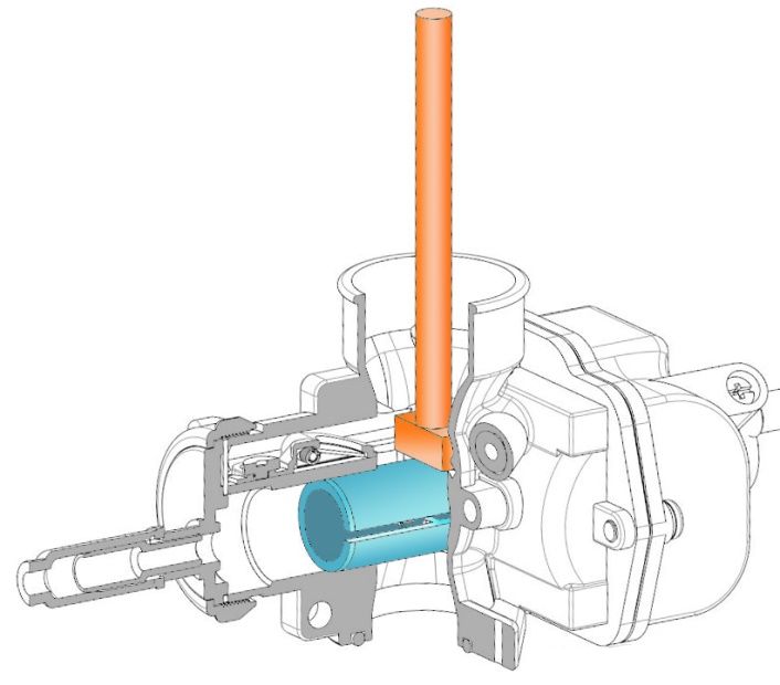
4. General Rules
  a. The terms stock, original equipment, OEM, unaltered, etc., refer to Original
     Equipment supplied by Briggs & Stratton or specified manufacturer.
  b. Only the original equipment Briggs & Stratton 206 #124332-8201-01 or
     Junior 206 #124332-8202-01 engines are allowed in the classes
     recommended herein.
  c. All parts must be unaltered Briggs & Stratton 206 parts specifically made for
     these engines by Briggs & Stratton. No aftermarket parts to be used unless
     specified in these regulations.
  d. All parts are subject to comparison with a known stock part. This includes
     specified and mandated aftermarket parts. Example: RLV exhaust and silencer.

  f. The tech official, at their sole discretion, may at any time replace a
     competitor’s sealed engine, carburetor, or head assembly with another sealed
     engine or known stock part. Failure to comply is grounds for disqualification.
  g. If a competitor’s part is replaced per 4f it must be drilled or reconfigured in a
     way that prohibits the reuse of that part.
  h. All Briggs & Stratton 206 classes must have a serialized block. Blocks without
     a factory serialization on the front base next to the oil drain are illegal in
     competition.
  i.   Standard organizational protest procedures can allow for short block
       inspection (seal removal) if a new, replacement short block, p/n 555715 is
       offered in replacement. Competitor short block to be forfeited to the series or
       club as terms of this procedure.

5. Things That Are NOT Permitted
  a. Tampering with either of the two factory-installed engine seals.
  b. Addition or subtraction of material in any form or matter.
          -   Exception – Valve maintenance (valve job). Valve seats must remain
              with the factory specification of 30 and 45 degree angles only. Valve
              seats of additional angles and/or angles not comparable to the factory
              stock of 30 and 45 degrees are not permitted. Grinding of valve stem or
              excessive material removal prohibited.
          -   Exception – Optimization of the slide opening in Briggs & Stratton
              Cadet, Novice, Junior 1, Junior 2 and ASN National Junior classes are
              permitted per Section 1 guidelines.
  -    “Blueprinting” unless stated herein.
  -    Modification to or the machining of any parts in order to bring them to stated
       minimum/maximum specification, (or for any reason).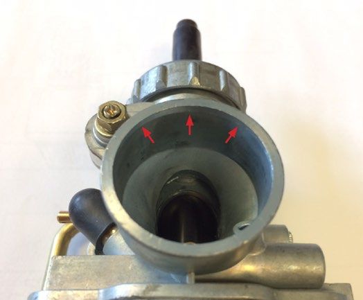
-    Machining or alteration of any kind to the engine or replacement parts
      unless specifically stated herein.
 -    Deburring, machining, honing, grinding, polishing, sanding, media blasting, etc.
 -    Sandblasting or glass-beading any interior engine surfaces.
 -    No device may be used that will impede, or appear to impede, airflow to
      the engine cooling system including the recoil starter or blower housing.

6. Factory Security Seals
   There are two custom security seals with matching serialization installed from
   the factory. Tampering of the seals is not permitted. Should the seals be
   tampered with, the engine is no longer eligible for competition. If an engine
   require dismantling for any reason that requires breaking of the seals,
   contact Briggs & Stratton at: briggsracing@basco.com

          The reflective hologram aluminum seal features        The orange housing seal features a red and black
         a black tracer wire and a silver or black anodized   tracer wire, etched ‘B&S Racing’ type, and matching
                           body as shown                                       seal serial numbers

     The only security seals that are legal have either a single black tracer wire with a
     reflective hologram seal or a red/black tracer wire with an orange housing seal.
     Plain cable seals are not approved for competition.

     Each competitor is responsible for the condition of their seal. We recommend that
     each seal be wrapped (plastic bag, etc.) to prevent exposure from harsh chemicals.

7. Technical Inspection Tools
     Briggs & Stratton have made available a number of tools for the convenience
     of technical checking of components when necessary. They are indicated
     throughout the rule set this way: “Tech Tool #” See Section 38 for tool
     description. The tools are available from Sox Racing (803) 791-7050.

8. Engine Ignition Switch
     The B&S ignition switch and wires must remain in stock location. It is
     not permitted to alter the OEM wiring.

9. Engine Air Filter
     The only air filter permitted is the Briggs & Stratton
     Green Air Filter Service Part #555729. No modification
     to the filter element is allowed.

     A protective shield may be attached for wet-weather competition.
     It is not permitted for the protective shield to create any ram-air effect.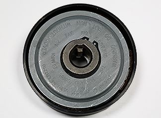
A fabric prefilter is allowed as long as it does not create a ram-air effect. Foam or
   any other prefilter material is NOT legal for use.

  A racer MUST start each race with the air filter properly attached but will
  NOT be penalized if the air filter falls off during the race. If air filter falls
  off during a race, it is STILL subject to tech.
10. Engine Fuel Recommendations
  Premium Gasoline no greater than 94 octane sold at normal roadside fuel
  stations open to the public. The addition of fuel additives in any manner is
  not permitted. Fuel dispensing location may be specified in Event
  Supplementary Regulations. Specific gravity and hydrometer testing
  are acceptable tests when used in accordance to sanctioning body
  guidelines.

11. Engine Oil
  High-quality synthetic oil within a 10W-20 range recommended. No oil
  additives are permitted.
  Briggs & Stratton only recommends the use of Briggs & Stratton 4T Synthetic
  Racing Oil. 4T was engineered exclusively for the rigors of high revving, air-
  cooled racing engines (available through both Briggs Racing and Amsoil
  dealers). The use of ‘karting’ or ‘automotive’ oils is not recommended as many
  are hydroscopic in nature (attract water), offer limited protection over time,
  and/or were engineered for pressure, not splash lube systems. The use of
  these oils can induce engine failure and/or accelerate wear.
  Engine oil testing/verification procedure is per standard sanctioning body
  guidelines.

12. Oil Breather
  Rocker cover oil breather must vent to a catch container.

13. Oil Catch Container
  An oil overflow catch system is mandatory. Overflow tube must run from the
  rocker cover breather to a catch container. The container must be vented to the
  atmosphere.

13.5 Oil Drain and Fill (Updated 2/15/21)
   One magnetic drain plug may be used (recommended in the lower opening).
   Oil fill caps are non-tech but must be secure and air tight.

14. Carburetor Overflow
   Carburetor overflow must be vented to a catch container. The container must
   be vented to the atmosphere.
15. Fuel Pump (Updated 2/15/21)

  Only fuel pump, B&S service part number 808656 or 597338, is legal for competition.
  This fuel pump can be identified by the Briggs & Stratton diamond logo and number
  808492 or 027013 stamped on the pump face. All other pumps are prohibited.
  It is prohibited to pulse from the intake manifold.

   Relocation of the fuel pump is legal as long as it is spaced to less than 3/4 inch
   off the control plate, B&S #555699, in a similar location that is both safe and
   secure. Measurement is from the base of the control plate to the bottom of the
   fuel pump. Vertical mounting or mounting the fuel pump upside down is
   illegal. The fuel pump must be pulsed from a pulse fitting mounted
   on the oil fill fitting located on the engine side cover. Aftermarket
   one-piece filler/pulse fittings such as shown on the right are
   permitted. Check valves prohibited.

  The use of silicone sealant on the brass vent IS permitted and recommended.
  A fuel pump return line to the fuel tank is prohibited.

  A fuel filter is not required but highly recommended to insure that dirt
  and contamination within your fuel system does not impact engine
  performance.
  The fuel filter itself is not a tech item but only one fuel filter is legal for use
  and it can only be located between the fuel tank and fuel pump inlet (not
  between the pump outlet and carburetor).

16. Cooling Shrouds, Covers and Blower Housings (Updated 2/15/21)
  All pieces of the engine cooling shroud/blower housing and control panel
  must be stock B&S and properly installed. Rewind housing and cooling
  shroud (air guard) must remain stock as painted from the factory.
  Engine Shroud may be painted any color. Any bolt, with the exception of
  the head bolt, that is used to secure sheet metal shrouds and covers may
  be replaced with larger diameter bolts.
  No taping, covering, or restricting of air to the rewind shroud is permitted.

  Quick-release throttle cable linkages are allowed, provided they are securely
  mounted to control plate.

17. Damaged Thread Repair
  It is permitted to use Heli-coil, Time-sert or a similar thread repair insert for
  shrouds, valve cover, oil drain, oil fill holes, blower housing, and exhaust pipe
  attachment studs on the head and lower brackets.
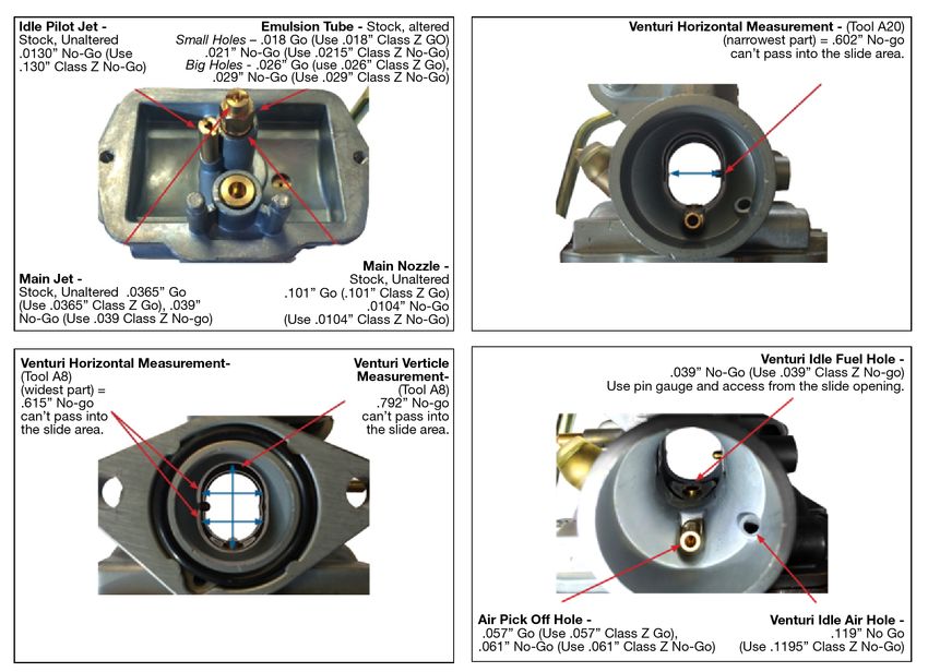
18. Carburetor & Intake Manifold (Updated 2/15/21)
  The B&S stock carburetor part #555658 is the only carburetor permitted.
  ‘Walbro’, ‘Briggs’ diamond logo and/or #590890 etched in the body are
  additional visual indicators. No alterations allowed unless stated below. All parts
  will be compared to a stock known B&S part for eligibility. This includes the
  nozzle, emulsion tube, jets, float, float needle and all other carburetor parts.
  It will be allowed however to adjust the float height by means of bending the
  small tab on the float arm.
  A slight chamfer around the choke bore ID (air horn)
  may be present. 1.149" no go Tech Tool A7.
  Both idle and main jet must remain stock,
  as shipped from the factory.

  Slide to remain B&S stock unaltered. Slide cutaway to be measured on flat
  surface. .075 no go Tech Tool A10. All intake manifold fasteners to
  remain factory stock. The use of studs, etc. is illegal.

  The fastener that attaches the carburetor to the intake manifold closest to
  the valve cover may be replaced by a longer drilled M6x1.0 bolt for wire
  engine sealing by a sanctioning body. Fastener must remain stock as
  approved by the sanctioning body

  All individual carburetor components must be tight, and must remain
  UNALTERED as shipped from the factory.

  B&S stock unaltered aluminum needle is required part number 555602
  marked #BGB. Needle to be inspected using Tech Tool A4. Needle, when
  placed in tool A4, should not protrude through the other side. If needle
  protrudes through the block it is out of specification.

  Throttle cable cap on the top of the carburetor must be properly installed
  and secured in the fully tight position.

  Metal choke cover must remain in place but may be secured with silicone
  or epoxy sealer. Additional pin punching is allowed to tighten choke cover.

  Air must only enter the engine from the air filter horn of the carburetor.
  Air entering through any other method or opening is illegal. An approved
  spray test method can be used for tech validation.
Idle Pilot Jet -        Emulsion Tube - Stock, Unaltered
     Stock, Unaltered
     .0130” No-Go (Use
     .0130” Class Z No-Go)

                                                Main Nozzle -
                                                Stock, Unaltered
                                     .101” Go (.101” Class Z Go)
                                                    .104” No-Go
                                      (Use .104” Class Z No-Go)

                                              Venturi Vertical
                                               Measurement

The “Slide Area” is the cylindrical space occupied by the carburetor slide as it moves up
and down. Measurement surfaces of Tool A8 and A20 may not enter this space.

Recommended Test Procedure:
   1. Set the carb down on its flange or nozzle
      opening. Ensure the tool (A8 or A20) is
      being positioned perpendicular to the
      direction of the carburetor slide travel.
   2. Pull the slide out of the venturi opening.
   3. Move the tool into the venturi vertically
      until it makes contact with the inside wall
      of the carburetor under its own weight.
   4. Move the slide in to check for contact with
      the measurement surface of the tool.
   5. If the slide can move to the full extent
      of its travel without contact with the
      measurement surface of the tool, the tool is not in the Slide Area.
      NOTE: Fastener on A8 is not part of the measurement surface and may enter.
   6. Repeat on reverse side of carburetor slide.
NOTE: Slide openings should be measured only with the
Briggs & Stratton slide tool listed on the tool reference chart.
Technical Item Description Tech
Tool
a. Needle Jet Needle Jet C-clip must be properly installed but may be
C-Clip installed at any of the 5 factory settings on the needle jet.
b. Throttle Cable Throttle cable cap on the top of the carburetor must
Cap be used and properly installed in tight position.
c. Choke Choke: OEM unaltered, but lever may be fastened open
with a spring, rubber band, wire, etc.
d. Idle Pilot Jet Idle Pilot Jet – Stock, Unaltered .0130” No-Go (Use .0130”
Class Z No-Go)
No drilling, reaming, elongating of the hole allowed.
.1195”
e. Idle Circuit .119” max. diameter. A small chamfer at the outer edge, as
Pin
Air Hole compared to a stock part, can be present. The
gauge
measurement of that chamfer is subject to sanctioning body
guidelines.
f. Main Jet Main jet – Stock, Unaltered .0365” Go (Use .0365” Class Z
Go), .039” No-Go (Use .039 Class Z No-go)
g. Emulsion Main nozzle – OEM stock unaltered hole size = .101, .104”
Tube Small holes – .018 Go (Use .018” Class Z GO) .021” No-Go
(Use .0215” Class Z No-Go)
Big Holes - .026” Go (use .026” Class Z Go), .029” No-Go
(Use .029” Class Z No-Go)
Venturi
h. Venturi Measurement: Vertical: .792 max inches. A8
Measurement
Horizontal: .615 max inches at widest part A8
Horizontal: .602 max inches at narrowest part. A20
Air Pick Off
i. Air pick off hole - .057 go .061 no go A9
Hole
Throttle bore – Must be as cast and bore max diameter =
j. Throttle Bore A7
.874 inches.
k. Venturi Venturi idle fuel hole =.039” No-Go (Use .039” Class Z No-
Idle Fuel Hole go)
l. Air Filter Air filter: Only GREEN air filter, part # 555729 is
allowed. Filter adapters are not allowed, filter must
attach directly
to carburetor air horn
Carburetor
m. Carburetor overflow: Must be vented to a catch container.
Overflow
O-Ring part number B&S part # 555601 is required
n. O-Ring
and must be unaltered.
A12
o. Intake Intake manifold – max length = 1.740 inches min to 1.760
Manifold inches max
Intake manifold – bore diameter = .885 inches min to
A11
.905 inches max
Choke
p. 1.149 no-go A7
Bore/Air Horn
Carb Slide
q. .075 no-go A10
Cutaway
r. Widest part of 2.640 A30
Combustion
Chamber19. Cylinder Head
a. The ONLY head casting for the B&S 206 herein is the ‘RT-1’, cast into the
head just off the head gasket surface (towards the rear of the engine, PTO
side). The overall head minimum thickness is 2.431”.
b. Cylinder head must be “as cast”. Factory machining marks left on the head
gasket surface is NOT a tech item.
c. Hard carbon may be scraped from head before measuring.
d. Depth of shallow area of combustion chamber must be .031 inch minimum.
This measurement to be taken with a depth gage on both the combustion side
and spark plug side of cylinder head.
e. Depth of the combustion chamber is .342” inches minimum.
f. Inspect retainers for alterations that would increase valve spring pressure -
.055 to .075 maximum flange thickness. Both intake and exhaust must have
OE stock B&S valve keepers.
g. Unaltered B&S part #555552 (exhaust) and #555551 (intake) can be checked
for appearance, weight, and dimensions. No machining, polishing, easing, or
alterations of any kind allowed. Valve surface must remain as factory, with
one single 45 degree face. No other additional angles allowed on any part of
the valve. Tech Tool A22.
h. Valve Guides: Replacement of valve guides with B&S part #555645
only is allowed. Maximum depth from the head gasket surface to the
intake valve guide is 1.255”.
i. Briggs & Stratton heat disperser, p/n 555690 can be installed in the
exhaust bolt boss per factory instructions.
20. Head Gasket
a. Unaltered B&S part #555723 is the only head gasket
allowed.
b. Minimum thickness allowed is .047". Measurement must
be performed using a micrometer. Readings are taken
from inside the cylinder hole of the gasket closest to the
combustion chamber (see diagram). Four measurements
are to be taken in the four defined quadrants with three
meeting the minimum thickness of .047”.
21. Ports
a. No de-burring, machining, honing, grinding, polishing, sanding, media blasting, etc.
b. The transition from intake bowl to port must have factory defined machining
burr at this junction.
No addition or subtraction of material in any form or matter.
No alterations of any kind may be made to the intake or exhaust ports.
c. Intake Port: Maximum diameter measurement = .918 inches max. Tech Tool A6.d. Exhaust Port AS CAST. Exhaust Outlet -.980 – Tech Tool A6.
e. Valve Seats. Intake and exhaust: Must remain factory specification with one
30 and one 45 degree angle only. Valve seats of additional angles and/or
angles not comparable to the factory stock are not permitted.
f. Valve maintenance permitted (valve job). Valve seats must remain with the
factory specification of 30 and 45 degree angles only. Valve seats of additional
angles and/or excessive material removed when compared to the factory
stock is prohibited.
g. Intake valve seat diameter inside = maximum .972 inches. Tech Tool A2.
h. Intake port pocket bowl (area just below valve seat) = .952 no go
Tech Tool A2
i. Exhaust valve seat diameter inside = maximum .850 inches. Tech Tool A1.
22. Valves
a. Intake valve
Minimum Weight of Valve 27.8 grams
Diameter of valve stem .246 to .247 inches
Diameter of valve head 1.055 to 1.065 inches
Tech Tool A17
Diameter of valve seat .972 inches ID maximum
Valve length Minimum 3.3655 inches
Height from angle of valve face to top of the valve .057 inches minimum
Tech Tool A26
b. Exhaust valve
Minimum Weight of Valve 27.2 grams
Diameter of valve stem .246 to .247 inches
Diameter of valve head .935 to .945 inches
Tech Tool A18
Diameter of valve seat .850 inches ID maximum
Valve length Minimum 3.3655 inches
Height from angle of valve face to top of the valve .060 inches minimum
Tech Tool A2723. Valve Springs
a. Valve Springs are single coil stock, unaltered B&S part #26826. Must be
identical in appearance to factory part and have 4.00 to 4.75 coils in stack.
b. Spring Wire Diameter: .103 to .107 inches
c. Valve spring length: .940 max inches Tech Tool A15 Inside diameter: .615” Go
(Use .615 Class Z Go), .635” No-Go (Use .635” Class Z No-Go)
24. Rocker Arms, Rocker Ball and Rocker Arm Studs
a. Rocker arm must be stock B&S serviced part #555711 (US) or #797443
(METRIC) and may not be altered in any way.
b. Rocker studs must be stock, unaltered B&S service part #694544 US (1/4-28
thread) or #797441 Metric (M8x1.00 thread) and in stock location.
Rocker arm #555711 (US) must be used with rocker stud #694544 (US).
Rocker arm #797443 (Metric) must be used with rocker stud #797441
(Metric).
c. Rocker Ball must B&S stock. Diameter .590 inch min. to .610 inch maximum.
Tech Tool A16.
d. Rocker arm mounting positions may not be altered in any manner. No heli-
coiling of mounting holes. No bending of studs.
e. Rocker arm stud plate must be bolted to the head with one, OEM stock B&S
gasket only – no alterations. Maximum thickness of gasket is .060 inches.
Rocker plate to head fastener holes must remain stock, .289” max.
f. Rocker arm – overall length 2.820 inch minimum. Can be checked with a pair
of dial calipers.
25. Push Rods
a. Push rods must be unaltered stock B&S service part #555531.
b. Push rod diameter .183 minimum inches to .190 maximum inches.
Push rod length 5.638 minimum inches to 5.658 maximum inches.
Tech Tool A5.
c. Push rod diameter to be checked 3 points along the length and must pass two
planes on each 360 degrees of rotation.
26. Engine Block
a. Engine block must be unaltered “as cast” B&S factory machined condition.
There must be no addition or subtractions of metal or any substance to the
inside or outside of the cylinder block.b. Both (2) B&S engine seals must be present with both the fastener and seal in
“as shipped” from the factory location and condition. Any defined tampering
with the fasteners or damage to the wire/seal itself (example: delaminated
hologram) are grounds for disqualification.
Take proper care of your seals to ensure their integrity. It is recommended
that you wrap your seals (using a plastic bag, etc.) to prevent exposure to
harsh solvents such as carb cleaner, etc...
c. Deck gasket surface finish is not a tech item. Piston pop up can be .0035”
maximum. Piston pop-up to be checked with flat bar in center of piston
parallel to piston pin and then again checked 90 degrees to piston pin. Push
piston down to take up rod play. Tech Tool A25.
Angle milling or peak decking is not allowed.
d. Carbon build-up can be removed before pop-up is measured as long as
material is not removed from the piston. Exception – Competitors can deburr
the manufacturing part number/marks IF needed as long as:
− Removal does not extend beyond the defined script area.
− De-burring does not extend below the original piston surface area.
− The original part numbers and script are still clearly visible.
e. Cylinder bore will not be bored oversize
f. Cylinder bore will not be re-sleeved.
g. Cylinder bore position is not be moved or angled in any manner.
h. Cylinder bore dimension: - Briggs & Stratton stock bore is 2.690”. Allowance
for wear is permitted up to 2.693” maximum for entire length, top to bottom.
i. Maximum stroke is 2.204”. Push piston down to take up rod play. Check
stroke on BDC to TDC. Tech Tool A21.
27. Valve Lift
a. Maximum valve lift is checked from the top of the valve spring retainer.
Valves must be adjusted to zero clearance.
b. Valve Lift: Camshaft check is taken at the valve spring retainers. With the lash
set at zero, the movement of the valve spring retainers may not exceed the
following: Intake and exhaust: .255 inches maximum.
27.5 Rocker Cover Fasteners
a. The rocker cover fastener closest to the carburetor is non-tech and may be
replaced with a drilled bolt for the purposes of wire engine sealing mandated
by a sanctioning body. The fastener must remain stock as approved by the
sanctioning body.28. Camshaft Profile Limits (measured at the push rod)
Push gently down on dial indicator stem to ensure that there is no lash when
push rods are going down.
NOTE: Due to the extended life of the engine, a single pƒoint on each lobe can be off by a
maximum of 2 degrees without issue, the exception being on the .006” check, both intake and
exhaust.
Intake lift Exhaust lift
0.006 59 TO 51 BTDC 0.006 101 TO 93 BBDC
0.020 16 TO 12 BTDC 0.020 59 TO 55 BBDC
0.050 .5 TO 4.5 ATDC 0.050 43 TO 39 BBDC
0.100 17 TO 21 ATDC 0.100 26 TO 22 BBDC
0.150 33.5 TO 37.5 0.150 9 TO 5 BBDC
0.175 43 TO 47 ATDC 0.175 1 TO 5 ABDC
0.200 54 TO 58 ATDC 0.200 11.5 TO 15.5
0.225 68 TO 72 ATDC 0.225 25 TO 29 ABDC
MAX LIFT 0.257 MAX LIFT 0.259
MIN LIFT 0.252 MIN LIFT 0.252
Intake lift Exhaust lift
0.225 38 to 34 BBDC 0.225 76 TO 72 BTDC
0.200 24.5 TO 20.5 0.200 62.5 TO 58.5
0.175 14 TO 10 BBDC 0.175 52 TO 48 BTDC
0.150 4.5 TO .5 BBDC 0.150 42 TO 38 BTDC
0.100 12 TO 16 ABDC 0.100 25.5 TO 21.5
0.050 29 TO 33 ABDC 0.050 8.5 TO 4.5 BTDC
0.020 45.5 TO 49.5 0.020 8 TO 12 ATDC
0.006 83 TO 91 ABDC 0.006 47 TO 55 ATDC
29. Flywheel
a. No modifications are allowed to the flywheel.
b. The minimum weight of the flywheel, fins and attachment bolts is 4 pounds 1
ounce.
c. Stock B&S service part #555683 only. No machining, glass beading, sand
blasting, painting or coating of flywheel is allowed.
d. A flywheel fan, B&S service part #692592, with broken fins must be replaced.
e. Stock, unaltered B&S flywheel key with the B&S logo is required. Width of the
key allowed is .1825”-.1875”. No offset keyways allowed.
30. Ignition System (Updated 2/15/21)
a. Unaltered B&S stock ignition part #555718 is mandatory. Only “GREEN”
ignition module allowed. Maximum RPM: 6,150.
Exception – Cadet Junior 206 class requires the use of unaltered B&S stock
ignition part #555725 (BLACK in color). Maximum RPM: 4,150.
b. Coil or its position, other than air gap, may not be altered in any way. Coil
mounting bolts must be stock and cannot be altered in any way to advance or
retard timing. Attachment bolts and/or bolt holes may not be altered.c. Spark plug: Only the AutoLite AR3910X spark plug UNALTERED in any way
from the OEM (B&S service part number #84005196) is permitted. Spark plug
must have the “AutoLite” and “AR3910X” identification on the insulator.
NOTE: Technical Inspectors may, at their own discretion, at any time,
visually inspect and retain a competitors spark plug and replace it with
a new AutoLite AR3910X spark plug.
Sealing washer must be in place, unmodified from the factory.
Temperature thermocouple is permitted as long as sealing washer and/or
cylinder heat shield with spark plug hole are not modified.
d. Spark plug connector: Only the OEM B&S part #555714 is permitted.
e. Magneto air gap is non-tech (recommended clearance of .016”)
f. Static check for timing:
- Install a degree wheel using a positive stop method.
- With the left edge of the first magnet aligned with the start of the lead leg
of the ignition (refer to photo), the engine must not exceed 26 degrees with
air gap set at .016”. Timing checked in the direction the engine operates.
31. Crankcase
Crankcase and cover must be Briggs & Stratton stock, unaltered, “as cast in
factory” condition. No alterations or subtractions of metal or any other
substance to crankcase cover.
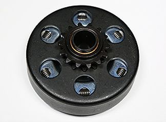
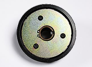
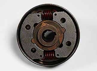
32. Clutch
a. Novice class must run the supplied Max-Torque clutch, part #555727. No
alteration to the clutch is allowed. Springs, driver (when applicable) and
clutch key are non-tech.b. Sportsman, Junior 1, Junior 2, Senior, and Masters Classes must run one of the
following clutches:
1. Inferno Racing by Hilliard: Fire, Flame, Blaze or Fury
2. Max-Torque: Draggin Skin or SS
3. Noram/Premier: Magnum, GE, Ultimate or Stinger*
* NOTE: Noram/Premier Stinger must be converted to stamped drum
(Noram P/N 01600715) to be legal for competition.
c. Sprocket conversion drums/kits manufactured by Inferno by Hilliard, Max-Torque
or Noram may be used. Sprocket conversion drums/kits from other
manufacturers are prohibited.
d. Refer to Page 21-25 for diagrams/photos of approved clutches
e. Clutch or sprocket conversion drum/kit must be used as shipped from the original
manufacturer – Inferno by Hilliard, Max-Torque or Noram. Mixing of parts between
clutch lines, manufacturers or removing parts (i.e.; grease guard, etc.) is
prohibited. No alteration or machining to the clutch allowed except light sanding
to shoe and drum mating surface for maintenance.
f. Interchangeable drivers (i.e.; 15T, 16T, etc) and driver configuration (#35 or
219), driver clip/lock, clutch key, and crankshaft fastener kit are non-tech. OEM
springs and weights MUST remain unmodified, OEM but are a racer’s choice.
Clutch coolers are not allowed. The use of aftermarket coatings is prohibited.
g. Clutch Claim Rule: Per standard sanctioning body guidelines, claiming can be
implemented, maximum of $160.00.
h. Manufacturers who wish to be considered for future rule sets may submit
requests to: briggsracing@basco.com
33. Starter
Recoil starter, B&S service part #695287, must be retained, as produced and
intact. Starter maybe rotated.
34. Exhaust Header (Updated 2/15/21)
a. Header must be RLV #EXF5507, for all non-Kid Kart classes.
b. Header length:
- EXF5507 will measure 18.75” +/- .25” along the short side using a 0.250”
wide tape measure.
c. Gasket and/or silicone are allowed to seal header to head (One gasket max)
d. Studs or bolts are permitted to fasten header to head.
e. Bolts or nuts must be safety wired to prohibit threads from backing out.
f. If header bolts loosen during a race but the header remains attached to the
head with two bolts/nuts, this is not grounds for disqualification.
g. Helicoiling of the exhaust is allowed.
h. Supplied header support brace is mandatory. The addition of a mechanical
support bracket (no welding involved) is allowed provided that there are
no alterations to the shape or dimensions of the exhaust configuration.i. Any modification for or use of an O2, EGT, CO2 sensor is prohibited.
35. Exhaust Silencer
Silencer must be RLV B91XL (part number 4104) with round
baffle holes only. Safety wiring of the silencer to header is
mandatory. All 4 baffles must remain unaltered and the hole size
can be verified using a no-go pin of .1285. Exhaust gases may only exit through
the muffler baffles. Muffler must be mounted on the header in a way that does
not allow exhaust to leak at this joint.
36. Exhaust Protection
The header and silencer must be completely wrapped (360 degrees) with a
non-asbestos, approved insulation material or sleeve starting approx. 3
inches from the exhaust flange.
37. Technical Inspection Tools
Videos of tools and processes are available at www.BriggsRacing.com.
38. IMPORTANT Online Support Resources
Please refer to www.BriggsRacing.com for a host of resources. Due to the sealed
nature of this engine we highly recommend reading and viewing important
documents and videos to insure a great racing experience.
a. 206 Engine tips and guide supplement – A must to print out and read
BEFORE installing your engine!
b. Carburetor tuning guide – Understand your carburetor to get the most out
of your 206.
c. Videos:
- Proper clutch installation: Properly installing your clutch will prevent
the possibility of crankshaft damage.
- Setting the float height: A simple video highlighting a necessary
technique to insure a properly tuned carburetor.
- Setting, measuring, and optimizing your junior slide restrictor.TOOL REFERENCE
.057” Go (Use .057” Class Z Go)
.061” No-Go (Use .061” Class Z No-Go)
Idle Pilot Jet – Stock, Unaltered .0130” No-Go
(Use .0130” Class Z No-Go)
Main Jet – Stock, Unaltered .0365” Go (Use .0365”
Class Z Go), .039” No-Go (Use .039 Class Z No-go)
Main nozzle – OEM stock unaltered hole size = .101,
.104”
Emulsion Tube - Small holes – .018 Go (Use .018”
Class Z GO) .021” No-Go (Use .0215” Class Z No-Go)
Big Holes - .026” Go (use .026” Class Z Go), .029”
No-Go (Use .029” Class Z No-Go)APPROVED CLUTCH GUIDE
Inferno by Hilliard Fire
FRONT BACK
Inferno by Hilliard Flame
FRONT BACK
If Bronze Bushing is used,
Grease Trap may be omitted
bearing style sprocket
Inferno by Hilliard Blaze
FRONT BACK
If Bronze Bushing is used,
Grease Trap may be omittedAPPROVED CLUTCH GUIDE
Inferno by Hilliard Fury
FRONT BACK
If Bronze Bushing is used,
Grease Trap may be omitted
Max-Torque Draggin Skin
FRONT BACK
Max-Torque SS
FRONT BACKAPPROVED CLUTCH GUIDE
Premier Magnum Heavy
FRONT BACK
Premier Magnum Light
FRONT BACK
Noram GE Heavy
FRONT BACKAPPROVED CLUTCH GUIDE
Noram GE Light
FRONT BACK
Noram GE Ultimate Heavy
FRONT BACK
Noram GE Ultimate Light
FRONT BACKAPPROVED CLUTCH GUIDE
Premier Stinger
FRONT BACK
Manufacturers who wish to be considered for future rule sets may submit
requests to: briggsracing@basco.com
TORQUE SETTING GUIDELINES
Description Tool Size Torque
Air Guard 7mm 40-50 lb-in. (4.5-5.6 Nm)
Blower Housing 10mm 60-110 lb-in. (7-12.5 Nm)
Rewind Starter 10mm 25-35 lb-in. (2.8-4 Nm)
Carburetor (to manifold) 10mm 80-110 lb-in. (9-12.4 Nm)
Cylinder Head Bolts 10mm 200-220 lb-in. (20-27 Nm)
Exhaust Brace Screws 10mm 95-125 lb-in. (11-14 Nm)
Flywheel Nut 15/16 105-115 ft-lbs. (142.4-156 Nm)
Flywheel Fan 10mm 180-240 lb-in. (20-27 Nm)
Intake (to Head) 5mm Allen 70-90 lb-in. (8-10.2 Nm)
Oil Drain Plug 10mm Star Socket 100-125 lb-in. (11-14 Nm)
Ignition Module 7mm 20-35 lb-in. (2.3-4 Nm)
Rocker Arm Stud 10mm 90-120 lb-in. (10-14 Nm)
Rocker Arm Plate 10mm 70-90 lb-in. (7.9-10.1 Nm)
Rocker Arm Set Screw 4mm Allen 50-70 lb-in. (5.6-7.9 Nm)
Spark Plug 5/8” Deep 140-200 lb-in. (15.8-22.6 Nm)
Top Control Plate 10mm 70-90 lb-in. (8-10 Nm)
Center Fuel Pump Bolt 10mm 50-60 lb-in. (5.6-6.8 Nm)
Valve Cover 10mm 30-60 lb-in. (3.5-7 Nm)You can also read