Deformation of loops in 2D packing of flexible rods - arXiv
←
→
Page content transcription
If your browser does not render page correctly, please read the page content below
Deformation of loops in 2D packing of flexible rods
arXiv:2012.06944v2 [cond-mat.soft] 25 Mar 2021

                                                               T A Sobral1,2 , V H de Holanda1,3 , F C B Leal1 , T T Saraiva1,4
                                                               1
                                                                 Departamento de Fı́sica, Universidade Federal de Pernambuco, 50670-901, Recife,
                                                               Brazil
                                                               2
                                                                 Instituto Federal de Educação, Ciência e Tecnologia do Rio Grande do Norte, RN
                                                               288, s/n, Nova Caicó, 59300-000 - Caicó, Brazil
                                                               3
                                                                 Instituto Federal de Educação, Ciência e Tecnologia do Sertão Pernambucano, PE,
                                                               Zona Rural, 56915-899 - Serra Talhada, Brazil
                                                               4
                                                                 National Research University Higher School of Economics, 101000, Moscow, Russia
                                                               E-mail: tteixeirasaraiva@hse.ru; thiago.sobral@ifrn.edu.br

                                                               26 March 2021

                                                               Abstract. The injection of a long flexible rod into a two-dimensional domain yields
                                                               a complex pattern commonly studied through elasticity theory, packing analysis, and
                                                               fractal geometries. “Loop” is a one-vertex entity that is naturally formed in this
                                                               system. The role of the elastic features of each loop in 2D packing has not yet been
                                                               discussed. In this work, we point out how the shape of a given loop in the complex
                                                               structure allows estimating local deformations and forces. First, we build sets of
                                                               symmetric free loops and performed compression experiments. Then, tight packing
                                                               configurations are analyzed by using image processing. We found that the dimensions
                                                               of the loops, confined or not, obey the same dependence on the deformation. The result
                                                               is consistent with a simple model based on 2D elastic theory for filaments, where the
                                                               rod adopts the shape of Euler’s elasticas between its contact points. The force and
                                                               the stored energy are obtained from numerical integration of the analytic expressions.
                                                               In an additional experiment, we obtain that the compression force for deformed loops
                                                               corroborates the theoretical findings. The importance of the shape of the loop is
                                                               discussed and we hope that the theoretical curves may allow statistical considerations
                                                               in future investigations.

                                                 Keywords: elasticity, elastic loops, elastica, packing, pattern formation

                                                 1. Introduction

                                                       The injection of filaments into cavities is a basic problem involving elasticity and
                                                 self-exclusion. These are two aspects of great importance in nature, with wide range of
                                                 influence from polymeric packing [1, 2] to DNA packaging in viral capsids [3, 4, 5, 6].
                                                 The structures formed by the confinement of wires packaged [3, 7] and crumpled surfaces
                                                 [8] present anomalous characteristics [3] that are of interest to soft matter physics and
                                                 statistical physics. The mechanical properties are influenced by the hierarchy of its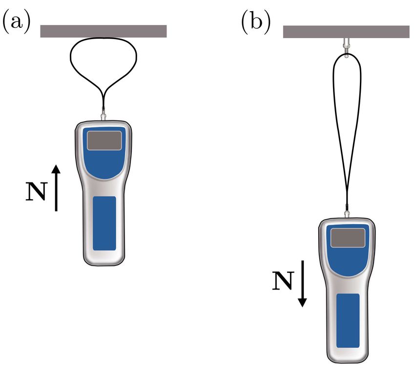
Deformation of loops in 2D packing of flexible rods                                             2

folds [9, 10] and show a behavior similar to that found in unbranched polymers diluted
in a solvent [2]. We focus on the two-dimensional confinement of an elastic slender rod,
which present interesting scaling properties [11], energy distributions [12, 13, 10], and
morphological phases [14]. The rigidity of the structure [3] is of particular interest in
the present study.
     In a typical 2D confinement as shown in Fig. 1(a), the formation of self-contact
points divides the area of the cavity into cells with a variable number of vertexes. “Loop”
is the term used to designate single-vertex cells [9], as those highlighted in Fig. 1(b). The

               Figure 1. (a) The packing of a 1 mm thick nylon fishing line into a circular cavity
               with a diameter of 200 mm. (b) The loops (in black) are closed domains with one
               vertex.

determination of the loops allows identifying the points of higher curvatures [15] and
helps to determine the morphology of the complex pattern [14]. The key concept here is
curvature, which links our work to the physics of pattern formation in protein chains and
membranes [16] and, not less astonishingly, quantum gravity [17]. Besides, the number
of loops gives the jamming length and the dynamic state of the system [18, 19]. Note
that the type of loops studied here, in which curvature reverses sign along its length,
can be unstable or less frequent in the case of 3D confinements, where torsion may have
a major influence and the curvature maintains a constant sign [20]. Even so, racquet
shapes were observed in fluctuating polymers [21, 22], nanotubes and biofilaments [23],
and the folding of paper stripes [24]. Here, we report a set of three experiments and
a model that describes the deformations of the loop. The main objective is identifying
physical quantities in the complex confined system by analyzing the shape of a single
loop.
     The article is organized as follows: in Sec. 2, we show our measurements of
fundamental geometric quantities of single loops under compression and compare them
to the case of loops from a packed conformation of longs rod inside 2D circular and
rectangular cavities; in Sec. 3, one can find solutions for the elasticity equation in 2D
for the loop under compression; in Sec. 4, it is described the experiment for measuring
the force of compressing and stretching the loops in the configurations obtained in the
previous section; and in Sec. 5, we show our conclusions.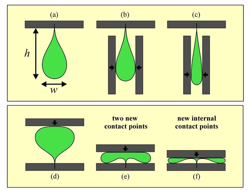
Deformation of loops in 2D packing of flexible rods                                           3

              Figure 2. Superior view of deformed loops: (a-c) compressing sideways by imposing
              smaller widths, and (d-f) compressing along the symmetric axis by imposing smaller
              heights.

2. Packing and compression of elastic loops

     The objective of the first experiment is to determine the mechanical response of
a single loop under compression. The loops were constructed by bending a piece of
rod to merge the ends into a vertex point. A bent rod leaves the planar configuration
when the ends are close to each other [25, 26], then transparent parallel plates are used
to constraint it. The rods used are either nylon fishing lines or polymeric tubes. The
fishing lines (packed in circular cavities) are 0.80 mm thick, and they are composed of
nylon, with Young’s Modulus of 2.7 (8) GPa and a Poisson ratio of 0.39. The polymeric
tubes (packed in rectangular cavities) are 5.0 (2.5) mm in external (internal) diameter,
and they are composed of flexible polyvinyl chloride, with Young’s Modulus of 3.3(1)
GPa and the Poisson ratio of 0.38. The constraint plates are made of acrylic with a
thickness of 1.0 cm. We also build planar loops with 1.0 cm wide ribbons and made
of 0.10 mm thick A4 paper or 0.21 mm thick transparent Mylar sheets. An interesting
point is that loops made from ribbons with large width are naturally planar [20], and
have the advantage of eliminating friction effects due to contact with parallel plates.
     The initial conformation is denominated “free loop”. The perimeter λ = λ0 is
defined when the flexible rod or ribbon is straight and was chosen randomly in an
interval λ0 = {97 − 366} mm. The loops are large to avoid plasticity effects. The height
h of the loop is defined along its symmetric axis as the distance from the vertex to the
top of the bulge. Perpendicularly, the largest width of the loop is w [Fig. 2(a)]. Both
h and w are measured with a digital caliper. The initial ratios h0 /λ0 = (0.424 ± 0.007)
and w0 /λ0 = (0.210 ±0.008) are essentially the same irrespective of the type of material.
For rods, we measured the dimensions h0 and w0 from the neutral axis.
     The experiment consists of compressing the loop along two perpendicular axes
(Fig. 2). In the first part, the loop is compressed between two parallel aluminum plates,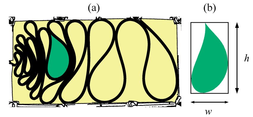
Deformation of loops in 2D packing of flexible rods                                                  4

requiring w to decrease as illustrated in Fig. 2(a-c). Care is taken to preserve the
loop as symmetric as possible. The system responds by increasing the height h. The
compressing continues until the physical limit w → 0 which leads to h → λ/2. During
this process, the contact points between the loop and the compression plates move
downwards as indicated by small arrows in Fig. 2(b-c). In the second part of the
experiment, the loop is compressed between two parallel aluminum plates, requiring h
to decrease as illustrated in Fig. 2(d-f). In this case, the system responds by increasing
w. The compressing continues until the physical limit h → 0 which leads to w → λ/2.
The experiment is performed horizontally over a table without gravitational effects.
     The results of the experiment illustrated in Fig. 2 are shown in Fig. 3(a-b) as a
h × w diagram, normalized by λ. The diagram is identical for loops built from ribbons
(Fig. 3a) and rods (Fig. 3b) and agrees with the theoretical description (solid line) based
on Euler’s Elastica which we discuss afterward. The values for the free loop are indicated
by a big cross. Since compressing w leads to higher h, the graph in Fig. 3(a-b) must be
read from the cross to the left. On the other hand, compressing h leads to higher w,
and the graph in Fig. 3(a-b) must be read from the cross to the right. Therefore, the
range of the data shown in Fig. 3(a-b) covers the entire physical domain, from values of
dimensions for the free loop to completely crushed shapes.

              Figure 3. The h × w diagram shows (I) the deformation of single loops made of (a)
              mylar ribbons and (b) fishing lines; and (II) image processing of packaged loops (c) in
              circular and (d) in rectangular cavities. The cross indicates the sizes of the free loop.
              The solid line indicates the theoretical curve. The inset in (a) shows a zoom to the
              lower right corner where corners appear due to the new contacts between the elastic
              line and the rigid plane. See text for further details.

     Due to its anisotropic shape, the loop’s response to compression depends on the
direction. As w decreases, the curvature becomes localized at a single point, the tip of
the loop, and the rest of the line is substantially straight, as depicted in Fig. 2(b-c). As
a consequence, in the limit w → 0, the height h → λ/2 and the diagram has no corners.
Compressing in the perpendicular direction, as shown in Fig. 2(d), a reduction in h leads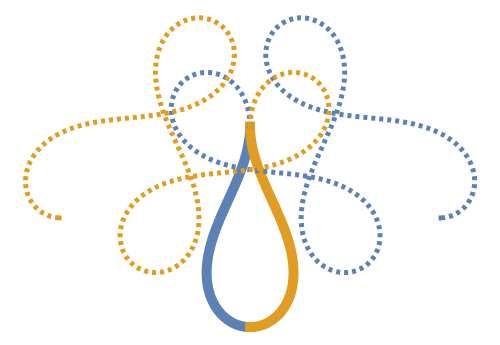
Deformation of loops in 2D packing of flexible rods                                              5

to an increase in w until we reach the first corner point at w1 /λ = (0.429 ± 0.005), as
displayed in Fig. 2(e). By decreasing h further, the curvature is distributed sideways,
and the new bulges eventually touch the compressing plane, as illustrated in Fig. 2(f).
If the compression continues beyond this second point at h2 /λ = (0.042 ± 0.002), the
curve follows towards the limiting value w → λ/2.
     To study the problem of 2D confining, the flexible rod can be split at the contact
points into pieces that are treatable numerically with Euler’s equation [27, 10]. The
fractal distribution of contact points along the wire in the cavity was studied in Ref. [15].
Instead of considering the intricate propagation of forces along all the length of the
wire [15, 14], we proposed a simpler method based on the shape of loops in 2D cavities
to obtain both qualitative and quantitative information about local deformations and
energy. The second experiment consists of the two-dimensional injection of thin rods into
planar slender cavities. The objective is to analyze how the loops, which are naturally
formed in the confinement, behave in light of the w ×h diagram. This experiment is also
divided into two parts. In the first one, nylon fishing lines with a diameter of 1.0 mm
are injected into circular cavities with 201 mm in diameter as shown in Fig. 1(a). In
the second part of the experiment, polymeric tubular rods with 50 mm in diameter are
injected into rectangular cavities of 400 × 200 mm2 as illustrated in Fig. 4(a). To ensure
two-dimensional confinement, the thickness of the cavities allows only one layer of the
rod. All injections are performed manually into a dry cavity, free of lubricants, at a rate
of about 1 cm/s. The injection stops when the system jams due to the rigidity around
the injection channel.

               Figure 4. (a) Digital image of the tight-packed flexible tube of 50 mm in diameter
               inside a rectangular cavity of 400 × 200 mm2 . (b) Each loop is framed and rotated
               to maximize the height inside a rectangle. The process defines h and w (see text for
               details).

     The particular conformation presented in Fig. 4(a) is chosen as a representative
case where we can briefly discuss the role of elasticity, self-exclusion, and friction with
the cavity. The first loops that formed are pushed away from the injection channel,
shown in the right region of Fig. 4(a). These loops are larger and require low values
for the injection force in the early stages. Observe that the shapes of the loops are
prevented from changing due to the contacts with the cavity and friction. The rod has
small self-contact regions and the stacked loops transmit the force through the system by
compressing each other. The geometric pattern and local rigidity are then governed by
Deformation of loops in 2D packing of flexible rods 6
the elasticity of the loops. On the other hand, the last loops are close to the injection
channel, see the left region of Fig. 4(a). The injection force in this stage is higher,
which reduces the perimeter of the loops and limits them to occupy the periphery of
the pattern, without contacting the cavity. The rod has large self-contact regions that
transmit the force through the system. In the case shown in Fig. 4(a) the loops are
compressed by neighbors in a configuration that resembles Fig. 2(a-c). In a cavity of
generic shape, however, we expect that the loops can interact also as in Fig. 2(d-f). For
example, there are differences between patterns generated from circular and rectangular
cavities [Compare Fig. 1(a) and Fig. 4(a)].
To build the h × w diagram for loops within cavities, we need to measure their
dimensions non-invasively. Digital photos were taken with an Olympus C-3040ZOOM
digital camera, positioned over the transparent cavity on a white horizontal table.
The image is subjected to some filtering operations, edge detection, and morphological
components using generic image processing programs, which allow selecting the loops,
as shown in Fig. 4(a). Within the cavities, loops interact intricately and assume non-
symmetrical shapes, so we redefine h and w appropriately for this context. We focus
here on the reading of the geometric pattern by prioritizing simple definitions ‡. First,
the selected loop is inscribed into a rectangle. Rotating the loop will change the aspect
ratio of the frame. The chosen angle is that which maximizes the height of the frame,
as shown in Fig. 4(b). This dimension is identified as h or w accordingly to the position
of the tip and the bulge of the loop. Following this procedure, all symmetrical loops
illustrated in Fig. 2 maintain their dimensions. The points at the edge of the loop are
interpolated by a curve that allows us to measure the dimensions h, w, and λ with the
same units. Such a method is repeated for each loop in the image. The result is shown
in Fig. 3(c) for loops inside circular cavities, and in Fig. 3(d) for loops inside rectangular
cavities.
The main result in Fig. 3 is that the loops obtained from the packing of rods
in a 2D cavity, whether in a circular or rectangular cavity as shown in Figs. 3(c-d),
follow the same diagram h × w as single handmade loops from mylar ribbons and
fishing lines, shown in Figs. 3(a-b). However, the data from packed loops distribute
themselves mostly on the left side of the diagram, instead of spreading over the whole
diagram. This is in agreement with the fact that the loops are aligned perpendicular
to the injection channel. The injection force then acts to compress the loops laterally,
reducing both their perimeter and width. However, Fig. 3(c) shows that few loops are
also longitudinally compressed in circular cavities. In this cavity rotation and slippage
are more accessible than in the rectangular one. In the general sense, this confirms that
how the loops populate the diagram depends on the shape and size of the cavity.
‡ For readers interested in numerical methods to quantify the shape of planar curves, see also Cartan’s
invariant signature [28]. Note that both methods are invariant under Euclidean transformations.Deformation of loops in 2D packing of flexible rods 7
3. Theoretical description
The theoretical description follows the elastic model for filaments, which allows
determining the shape of single loops [29, 30, 25]. Besides, values of compressive force
and elastic energy stored in the loops are found as functions of deformation. We describe
the filament by a purely elastic curve. The force vector is constant along the slender
rod, and it points in the direction of a horizontal x-axis, F(s) = F î. Since θ is the
angle between the infinitesimal length ds and the direction of the force F, the shape is
governed by infinitesimal torques dΓ(s) = F sin θ ds. The elasticity of the rod is given
by the bending rigidity µ, which relates the torque to the local curvature, Γ(s) = −µ dθ
ds
.
From this, we can write a second-order differential equation for the angle:
d2 θ
= − sin θ, (1)
ds̃2
p
where the tilde over any quantity q means q̃ ≡ q F/µ. We chose the initial angle
θ(0) = 0 and the initial curvature θ̇0 (used as a parameter) as boundary conditions.
The Cartesian’s coordinates are given by integration of dx̃(s̃)/ds̃ = cos θ and dỹ(s̃)/ds̃ =
sin θ, starting from the origin: x̃(0) = ỹ(0) = 0. The family of solutions [Figs. 5(a-c)]
are written in terms of elliptic integrals and elliptic functions, and the elliptic parameter
p ≡ θ̇02 /4 determines the overall shape [30].
The free loop, sketched in Fig. 2(a), presents a special point where the branches of
the rod tangentially merge. Therefore, we selected the solution with a single self-contact
point, at s̃ = s̃∗ , by imposing the conditions:
dx̃(s̃)
x̃(s̃∗ ) = x̃(0) and = 0. (2)
ds̃ s̃=s̃∗
That allows us to write an equation for p in terms of elliptic functions. The numerical
solution provides the known value p∗ = 0.731183 [22]. Regarding the dimensions of the
free loop, the length s̃∗ characterizes a half perimeter λ̃/2, the coordinate ỹ of the vertex
point defines the height h̃, and the maximum value of x̃ delineates the half-width w̃/2
of the free loop. We find h0 /λ = 0.424308 and w0 /λ = 0.204214, irrespective of the
bending rigidity. Those values agree with the experimental finding, as the big crosses
in Fig. 3 shows. Once we find the value of s̃∗ , the force required to build the free loop
is F = µ(s̃∗ /s∗ )2 = 4µ(s̃∗ /λ)2 .
Our model for a deformed symmetrical loop requires attention to the contact points,
where external forces act. As we can see in Fig. 2, there is a contact point in the
middle of the loop when we compress it longitudinally and two contact points when
we compress it laterally. To simplify the problem, we assume that lateral compression
of the loop is equivalent to longitudinal elongation. In this manner, all compression
in Fig. 2 can be described by the application of a single normal force N = N ĵ at the
middle point of the loop, with N > 0 for the compressing sideways and N < 0 for
longitudinal compressing. This approach proved to be sufficiently accurate when the
results corroborate the experimental data well.Deformation of loops in 2D packing of flexible rods 8
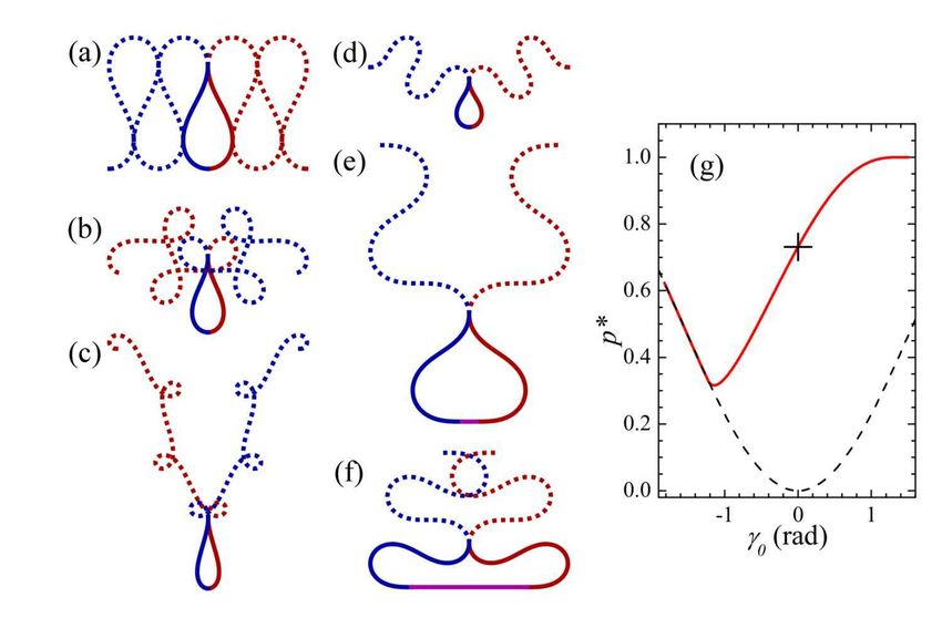
Figure 5. The family of solutions of Eq. 1 for x(0) = y(0) = θ(0) = 0 is shown for (a)
p = 0.3, (b) p∗ = 0.73118, and (c) p = 0.999. Here, the deformed loop is modeled by a
solution in coordinates rotated by an angle (d) γ0 = π/6 rad (p∗ = 0.906799) and (e)
γ0 = −π/6 rad (p∗ = 0.509152) and its reflection on the vertical axis. Note that the
solutions are periodic along the line of force.
For the deformed loop, the vertical force changes the reference axis of the curve,
because the total force has now two components F = P î + N ĵ [Fig. 5(d)]. Eq. (1)
remains valid for a coordinate system rotated by an angle of γ0 ≡ tan−1 (N/P ), but the
contour conditions, Eq. (2) are the same. That leads us to write an equation for p in
terms of elliptical functions, as before, with the solution p∗ now depending on the angle
γ0 . Therefore, the deformed loop is composed of two mirrored elasticas that start from
the origin and merge at the vertex, as can be seen in Fig. 5(d-e).
Figure 6(a-f) shows some situations where two symmetrical elasticas (dashed lines)
merge to compose the deformed loop (solid lines). The free loop corresponds to γ0 = 0,
illustrated in Fig. 6(a). In the case γ0 > 0, shown in Fig. 6(b-c), the curve intersects,
indicating that the solution p∗ is greater than that of the free loop. In the case γ0 < 0,
shown in Fig. 6(d-f), the curve no longer intersects, indicating that the solution p∗ is
less than that of the free loop.
Figure 6. The symmetric loop is composed of two elasticas (a-f) rotated respectively
by γ0 = {0, 0.60, 1.20, -0.55, -1.27, -1.82} rad. (g) p∗ dependence with the compression
force through γ0 . The dashed line corresponds to γ̇0 = 0 case. See text for details.Deformation of loops in 2D packing of flexible rods 9
Figure 6(g) summarizes our results by showing the dependence of the elliptical
parameter p∗ as a function of the angle γ0 . As usual, the solution for the free loop is
illustrated by the large cross. In general, the elliptical parameter p∗ departs from the
free loop result for γ0 6= 0. The limit case γ0 → ∞ leads to the homoclinic elastica
p∗ → 1. At this limit, the loop is mostly a straight line with a very high curvature
concentrated in a minuscule region. On the other hand, when γ0 < 0, p∗ (γ0 ) is not a
monotonic function because of a physical constraint. The dashed line in Fig. 6(g) shows
the values of p∗ that satisfy the zero curvature condition at the origin. This condition
in the rotated coordinate system provides p∗ = sin2 (γ0 /2). That is a physical constraint
in our experiment because the compression plate does not allow for a change in the
curvature signal, as Fig. 2(e) shows well. To extend our model somewhat beyond this
limitation, we have included a straight line between the origin and the inflection point,
as illustrated in Fig. 6(f). We do not cover the entire region γ0 < 0 because new self
contacts appear when the deformation is high enough [Fig. 2(f)].
Once the parameter p∗ is found, the appropriate planar elastica is defined. Although
the problem is solved in rotated coordinates, we define the central quantities of interest
in the original coordinate system: the half perimeter λ̃/2 = s̃∗ obeys the condition
x̃(s̃ 6= 0) = 0 (length s̃∗ of the vertex), the height h̃ is given by the coordinate ỹ(s̃∗ )
and the width w̃ is obtained by the maximum value of x̃(s) between 0 and s∗ . In
the extension of the model for γ0 < 0, only the half perimeter needs adjustment to
λ̃/2 = s̃∗ + ℓ̃, where ℓ̃ is the distance between the origin and the inflection point (fixed
at s = 0).
One builds a parametric h(γ0 ) × w(γ0) diagram. Fig. 3 shows the result as a
continuous line. Despite the approximations and extensions that we added to a purely
elastic model, the diagram describes very well the general behavior of deformed loops
even in the complex case of two-dimensional packing. That inspired us to perform a
third experiment, exploring the fact that the force profile F (γ0 ) = 4µ(s̃∗ (γ0 )/λ)2 is
theoretically available.
4. Measuring the force for compression and stretching of loops
In a third experiment, we measured the force N versus deformation (∆h/λ) through
an Instrutherm DD-500 dynamometer, with instrumental precision of 0.01 N, coupled
in automatic equipment, whose spatial displacements were given in steps of 2 mm. The
loop samples were made with strips of acetate sheets 0.5 mm thick and 1.00 ± 0.02 cm
wide. 10 measurements were made with strips of different sizes. The measurements
obey two steps: (i) we attach the vertex of the loop to the probe tip of a dynamometer
and (ii) we reset the dynamometer measurement after connecting the loop to it. We
compress the loop by pushing the protrusion against a fixed wall (see Fig. 7 (a) - in this
process N < 0), while in the stretch we fix a metal hook on its protuberance, then we
stretch the loop by pulling the dynamometer (see Fig. 7 (b) - in this process N > 0).
The results obtained for the measurements of the force (N) were shown in Fig. 8Deformation of loops in 2D packing of flexible rods 10
as black dots. The force increases faster during the stretching than in the compression
process due to the asymmetry of the loop. The dashed line in Figure 8 points to the
limit h tending to λ/2, where the force and energy diverge because of the small radius
of curvature of the strip due to stretching. The agreement between the model and
the experiment allows us to estimate the strength and energy stored for loops within
complex patterns.
Figure 7. Schemes of the measurements of the force N (a) to compress the loop
and (b) to stretch the loop. This experiment was executed along the horizontal plane
perpendicular to the gravitational force.
The agreement between the theoretical curve and the experimental data (Fig. 8)
shows the relevance of this purely elastic model. We can calculate the force associated
with a given shape, F = µ(s̃, s)2 . The result for the force is shown in Fig. 8 and (inset)
the energy cost of deformation is obtained by integrating the force N over infinitesimal
R
displacements of the height ∆E = W = N dh. Note that big crosses in Fig. 8 indicate
the values of the initial conditions.
Measurements of forces involved in the deformation of loops are useful to obtain
a better understanding of the configurations of the injected wire inside the cavity. It
is possible to integrate the force along the wire to obtain total energy in a specific
configuration. On the other hand, it is possible to determine the energy distribution
in the cavity using the loop density and our local energy measurements for each loop.
We hope to carry out new experiments to test our hypothesis and theoretical model
and to compare them with other previous publications [15]. Also, we believe that
our experimental and theoretical results may be useful in the study of other chain-
like packing systems, such as the case of genetic material into virions. For example,Deformation of loops in 2D packing of flexible rods 11
Figure 8. The force N as a function of the deformation ∆h/λ for elastic loops.
The black dots correspond to the data obtained with the experimental setup. The
continuous red line corresponds to the theoretical prediction, while the dashed lines
indicate the physical limit of deformation. The inset shows the elastic energy stored
in the loops, ∆E, as a function of the deformation ∆h/λ. See text for details.
these configurations are important in bacteriophages that need high pressures within
the cavity to eject their genetic material to pass through the cell membrane [31].
5. Conclusion
In this work, we suggest new methods to analyze the deformation of a flexible rod
packed into a 2D cavity. The h×w diagram in Fig. 3 enables us to calculate the perimeter
of the loops and their deformation level, compared to a simple model based on Euler’s
Elastica [30]. The purely elastic case is an important reference [12, 32], and the graphs
in Fig. 8 allow us to estimate the forces and stored energy in any loop immersed in a
complex pattern. In this physical system, friction and plasticity play very important
roles [14, 13], but the effect on each loop needs further attention. Finally, the results of
the dependence of the stored energy on the loop deformation open up new possibilities
for the application of statistical techniques to 2D confining of flexible rods.
Acknowledgments
We acknowledge Professor Eduardo O. Dias from UFPE for fruitful discussions. The
present work was supported by CNPq, Conselho Nacional de Desenvolvimento Cientı́fico
e Tecnológico, Brazil (numbers 157218/2012-0, 141813/2016-4, and 152053/2016-6).
References
[1] Paul J. Flory. Principles of polymer chemistry. Cornell University Press, 1953.
[2] Pierre-Gilles de Gennes. Scaling concepts in polymer physics. United Kingdom by Cornell
University Press Ltd., Ithaca, United States, first edition, 1979.Deformation of loops in 2D packing of flexible rods 12
[3] M A F Gomes, V P Brito, A S O Coelho, and C C Donato. Plastic deformation of 2d crumpled
wires. Journal of Physics D: Applied Physics, 41(23):235408, 2008.
[4] N. Stoop, J. Najafi, F. K. Wittel, M. Habibi, and H. J. Herrmann. Packing of elastic wires in
spherical cavities. Phys. Rev. Lett., 106:214102, May 2011.
[5] Roman Vetter, Falk K Wittel, and Hans J Herrmann. Morphogenesis of filaments growing in
flexible confinements. Nature communications, 5, 2014.
[6] V. H. de Holanda and M. A. F. Gomes. Scaling, crumpled wires, and genome packing in virions.
Phys. Rev. E, 94:062406, Dec 2016.
[7] M. A. F. Gomes, F. F. Lima, and V. M. Oliveira. Plastic properties of crumpled wires.
Philosophical Magazine Letters, 64(6):361–364, 1991.
[8] M A F Gomes, T I Jyh, T I Ren, I M Rodrigues, and C B S Furtado. Mechanically deformed
crumpled surfaces. Journal of Physics D: Applied Physics, 22(8):1217–1221, aug 1989.
[9] C. C. Donato, M. A. F. Gomes, and R. E. de Souza. Crumpled wires in two dimensions. Phys.
Rev. E, 66:015102, Jul 2002.
[10] S. Deboeuf, M. Adda-Bedia, and A. Boudaoud. Energy distributions and effective temperatures
in the packing of elastic sheets. EPL (Europhysics Letters), 85(2):24002, 2009.
[11] C. C. Donato, M. A. F. Gomes, and R. E. de Souza. Scaling properties in the packing of crumpled
wires. Phys. Rev. E, 67:026110, Feb 2003.
[12] Laurent Boué and Eytan Katzav. Folding of flexible rods confined in 2d space. EPL (Europhysics
Letters), 80(5):54002, 2007.
[13] Y. C. Lin, Y. W. Lin, and T. M. Hong. Crumpling wires in two dimensions. Phys. Rev. E,
78:067101, Dec 2008.
[14] N. Stoop, F. K. Wittel, and H. J. Herrmann. Morphological phases of crumpled wire. Phys. Rev.
Lett., 101:094101, Aug 2008.
[15] C. C. Donato and M. A. F. Gomes. Condensation of elastic energy in two-dimensional packing of
wires. Phys. Rev. E, 75:066113, Jun 2007.
[16] Jaime Agudo-Canalejo and Ramin Golestanian. Pattern formation by curvature-inducing proteins
on spherical membranes. New Journal of Physics, 19(12):125013, dec 2017.
[17] B. Carneiro da Cunha. Crumpled wires and liouville field theory. EPL (Europhysics Letters),
88(3):31001, 2009.
[18] T A Sobral and M A F Gomes. Tight packing of a flexible rod in two-dimensional cavities. Journal
of Physics D: Applied Physics, 48(33):335305, 2015.
[19] T. A. Sobral and M. A. F. Gomes. Packing loops into annular cavities. Phys. Rev. E, 95:022312,
Feb 2017.
[20] Yasuaki Morigaki, Hirofumi Wada, and Yoshimi Tanaka. Stretching an elastic loop: Crease,
helicoid, and pop out. Phys. Rev. Lett., 117:198003, Nov 2016.
[21] B Schnurr, F. C MacKintosh, and D. R. M Williams. Dynamical intermediates in the collapse of
semiflexible polymers in poor solvents. Europhysics Letters (EPL), 51(3):279–285, aug 2000.
[22] B. Schnurr, F. Gittes, and F. C. MacKintosh. Metastable intermediates in the condensation of
semiflexible polymers. Phys. Rev. E, 65:061904, Jun 2002.
[23] Adam E. Cohen and L. Mahadevan. Kinks, rings, and rackets in filamentous structures.
Proceedings of the National Academy of Sciences, 100(21):12141–12146, 2003.
[24] L Mahadevan and Joseph B Keller. Periodic folding of thin sheets. Siam Review, 41(1):115–131,
1999.
[25] V. G. A. Goss, G. H. M. van der Heijden, J. M. T. Thompson, and S. Neukirch. Experiments
on snap buckling, hysteresis and loop formation in twisted rods. Experimental Mechanics,
45(2):101, 2005.
[26] F. Bosi, D. Misseroni, F. Dal Corso, and D. Bigoni. Self-encapsulation, or the ‘dripping’ of
an elastic rod. Proceedings of the Royal Society of London A: Mathematical, Physical and
Engineering Sciences, 471(2179), 2015.
[27] L. Boué, M. Adda-Bedia, A. Boudaoud, D. Cassani, Y. Couder, A. Eddi, and M. Trejo. SpiralDeformation of loops in 2D packing of flexible rods 13
patterns in the packing of flexible structures. Phys. Rev. Lett., 97:166104, Oct 2006.
[28] Eugenio Calabi, Peter J. Olver, Chehrzad Shakiban, Allen Tannenbaum, and Steven Haker.
Differential and numerically invariant signature curves applied to object recognition.
International Journal of Computer Vision, 26(2):107–135, Feb 1998.
[29] L. D. Landau and E. M. Lifshitz. Theory of Elasticity. Pergamon Press, 1986.
[30] Michel Nizette and Alain Goriely. Towards a classification of euler–kirchhoff filaments. Journal
of Mathematical Physics, 40(6):2830–2866, 1999.
[31] Prashant K Purohit, Mandar M Inamdar, Paul D Grayson, Todd M Squires, Jané Kondev, and
Rob Phillips. Forces during bacteriophage dna packaging and ejection. Biophysical journal,
88(2):851–866, 2005.
[32] S. Deboeuf, E. Katzav, A. Boudaoud, D. Bonn, and M. Adda-Bedia. Comparative study of
crumpling and folding of thin sheets. Phys. Rev. Lett., 110:104301, Mar 2013.You can also read